Tecnologic THP 84 User manual

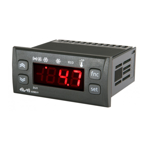
THP 84
REGOLATORE ELETTRONICO
DIGITALE A MICROPROCESSORE
MICROPROCESSOR-BASED DIGITAL
ELECTRONIC CONTROLLER
ISTRUZIONI PER L'USO
OPERATING INSTRUCTIONS
Vr. 02 (I - GB) - cod.: ISTR 00132
TECNOLOGIC S.p.A.
VIA INDIPENDENZA 56
27029 VIGEVANO (PV) ITALY
TEL.: ++39 0381 69871 - FAX: ++39 0381 698730
internet : http:\\www.tecnologic.it
e-mail: [email protected]
PREMESSA: Nel presente manuale sono contenute le informazioni
necessarie ad una corretta installazione e le istruzioni per l'utilizzo e la
manutenzione del prodotto, si raccomanda pertanto di leggere attentamente
le seguenti istruzioni. Ogni cura è stata posta nella realizzazione di questa
documentazione, tuttavia la TECNOLOGIC S.p.A. non può assumersi
alcuna responsabilità derivante dall'utilizzo della stessa. Lo stesso dicasi
per ogni persona o società coinvolta nella creazione del presente manuale.
La presente pubblicazione è di esclusiva proprietà della TECNOLOGIC
S.p.A. la quale pone il divieto assoluto di riproduzione e divulgazione,
anche parziale, se non espressamente autorizzata. La TECNOLOGIC S.p.A.
si riserva di apportare modifiche estetiche e funzionali in qualsiasi
momento e senza alcun preavviso.
PREVIOUS STATEMENT: In this manual are contained all the necessary
information for a correct installation and the instructions for the use and
the maintenance of the product; we recommend, therefore, to read
carefully the following instructions. The maximum care has been used in
the realisation of this document, anyway TECNOLOGIC S.p.A. does not
assume any responsibility deriving from the use of itself. The same
consideration has to be done for each person or Company involved in the
creation of this manual. The herewith issue is an exclusive property of
TECNOLOGIC S.p.A. which forbids any reproduction and divulgation,
although partial, if not expressly authorised. TECNOLOGIC S.p.A.
reserves the right to execute aesthetically and functional modifications, at
any moment and without any notice.
INDICE
PROBLEMI , MANUTENZIONE E GARANZIA7
TABELLA PARAMETRI6.1
DESCRIZIONE DEI PARAMETRI6
PROGRAMMAZIONE5
INTERFACCIA SERIALE RS 4854.15
INGRESSI DIGITALI AUSILIARI4.14
FUNZIONE ALLARME DI LOOP BREAK4.13
FUNZIONE ALLARME DI HEATER BREAK4.12
FUNZIONAMENTO DELLE USCITE DI ALLARME4.11
RAGGIUNGIMENTO DEL SET POINT A VELOCITA'
CONTROLLATA
4.10
USCITE DI REGOLAZIONE ANALOGICHE4.9
FUNZIONI DI AUTOTUNING E SELFTUNING4.8
REGOLATORE PID PER AZIONAMENTI MOTORIZZATI4.7
REGOLATORE PID A DOPPIA AZIONE4.6
REGOLATORE PID A SINGOLA AZIONE4.5
REGOLATORE ON/OFF4.4
CONFIGURAZIONE INGRESSO DI MISURA4.3
SELEZIONE DEL SET POINT ATTIVO4.2
STATI DI REGOLAZIONE4.1
FUNZIONAMENTO4
INSTALLAZIONE3
DATI TECNICI2
CODIFICA DELLO STRUMENTO1.2
PANNELLO FRONTALE1.1
DESCRIZIONE GENERALE1
INDEX
TROUBLES, MAINTENANCE, GUARANTEE7
PARAMETERS TABLE6.1
DESCRIPTION OF PARAMETERS6
PROGRAMMING5
RS 485 SERIAL INTERFACE4.15
AUXILIARY DIGITAL INPUTS4.14
LOOP BREAK ALARM FUNCTION4.13
HEATER BREAK ALARM FUNCTION4.12
ALARM OUTPUTS OPERATING MODE4.11
REACHING OF SET POINT WITH CONTROLLED SPEED4.10
ANALOGUE CONTROL OUTPUTS4.9
AUTOTUNING AND SELFTUNING FUNCTIONS4.8
PID CONTROL FOR MOTORIZED ACTUATORS4.7
DOUBLE ACTION PID CONTROL4.6
SIGLE ACTION PID CONTROL4.5
ON/OFF CONTROL4.4
CONFIGURATION OF THE MEASURE INPUT4.3
ACTIVE SET POINT SELECTION4.2
CONTROL STATE4.1
OPERATING MODE4
INSTALLATION3
TECHNICAL DATA2
INSTRUMENT CODE1.2
FRONT PANEL1.1
GENERAL DESCRIPTION1
1 - DESCRIZIONE GENERALE
Il modello THP 84 è un regolatore digitale a microprocessore "single
loop", con regolazione ON/OFF, PID a singola azione, PID a doppia azione
(diretta e inversa) o PID Velocity per comando di azionamenti motorizzati
a posizionamento temporale e con funzioni di AUTOTUNING (sia
oscillatorio che Fast) e SELFTUNING per la regolazione PID . Lo
strumento offre inoltre la la possibilità di disporre di interfaccia di
comunicazione seriale RS485. Il valore di processo viene visualizzato su 4
display rossi(PV) , il valore di Set su 4 display verdi (SV), mentre lo stato
delle uscite viene segnalato da 3 led. Lo strumento prevede la
memorizzazione di 4 Set-Point di regolazione e può avere sino a 2 uscite :
1 uscita di regolazione (C1) + 1 uscita di regolazione o di allarme (C2/A4),
oppure 1 uscita di regolazione (C1) + 1 uscita di allarme Heater Break o di
allarme (HB/A3), tutte a relè, per il pilotaggio di relè statici (SSR) o
analogiche (solo per C1, C2). L'ingresso può essere per sonde di
temperatura (Termocoppie, Termoresistenze Pt100 o segnali in mV) o per
segnali analogici normalizzati (0/4..20 mA, 0/1..5 V, 0/2..10 V, ). Lo
TECNOLOGIC - THP 84 USER MANUAL (I - GB) - Vr. 02 - ISTR 00132 - PAG. 1

strumento può disporre inoltre di un ingresso per trasformatore
amperometrico per la funzione di Heater Break e di 2 ingressi digitali
ausiliari che consentono la selezione remota del Set Point attivo tra quelli
memorizzati e/o dello stato di regolazione (off, manuale o automatica). In
alternativa agli ingressi digitali ausiliari è possibile disporre dell'interfaccia
seriale RS485 attraverso la quale è possibile il controllo remoto completo
dello strumento.
1.1
-
PANNELLO FRONTALE
1 - Tasto P : Utilizzato per la programmazione dei parametri di
funzionamento. Viene usato quindi per confermare i dati impostati e
passare quindi al parametro successivo
2 - Tasto UP : Utilizzato per incrementare la cifra sulla quale si trova il
"cursore" (nel caso di parametri non numerici, il tasto "UP" serve per
selezionare le opzioni disponibili), per cambiare il set point attivo, per
visualizzare la potenza di regolazione in uscita, per comandare
manualmente l’apertura in caso di azionamenti motorizzati, per scorrere i
parametri a ritroso (insieme al tasto “P”)
3 - Tasto LEFT : Utilizzato per spostare il "cursore" (cifra che lampeggia)
sulla cifra che si vuole modificare, per visualizzare la corrente misurata
dall’ingresso TAHB, per resettare la memoria allarme, per comandare
manualmente la chiusura in caso di azionamenti motorizzati .
4 - Led C1 : Indica lo stato dell'uscita C1 on (acceso) o off (spento)
5 - Led C2/A4 : Indica lo stato dell'uscita C2/A4 on (acceso) o off (spento)
6 - Led HB/A3 : Indica lo stato dell'uscita HB/A3 on (acceso) o off
(spento)
7 - Led AT : Indica la funzione Selftuning inserita (acceso) o lo stato di
Autotuning in corso (lampeggiante)
8 - Led MAN : Indica lo stato di regolazione manuale (lampeggiante)
9 - Display PV: Indica normalmente il valore di processo
10 - Display SV: Indica normalmente il valore di Set Point
1.2 - CODIFICA DELLO STRUMENTO
THP 84 a b cc d e f g hh
a = INGRESSO
T : Per sonde di temperatura (Termocoppie, Termoresistenze Pt100) o
segnali in mV (0...50 mV)
I : Segnali normalizzati 0/4...20 mA
V : Segnali normalizzati 0/1...5 V
W : Segnali normalizzati 0/2...10 V
b = USCITA C1
R : A relè
O : Uscita in tensione 24 VDC per SSR
C : Analogica 0/4...20 mA
V : Analogica 0/2...10 V
cc = SECONDA USCITA
- - : Non Presente
R - : Di regolazione (C2) o di allarme (A4) con uscita a Relè
O - : Di regolazione (C2) o di allarme (A4) con uscita in tensione 24 VDC
per SSR
C - : Di regolazione con uscita analogica 0/4...20 mA (C2)
V - : Di regolazione con uscita analogica 0/2...10 V (C2)
- R : Di allarme Heater Break (HB) o di allarme (A3) con uscita a Relè
- O : Di allarme Heater Break (HB) o di allarme (A3) con uscita in tensione
24 VDC per SSR
d = CONTROLLO PER ATTUATORI MOTORIZZATI
M : Predisposizione controllo per attuatori motorizzati (con uscite C1 e C2
a relè)
- : Controllo per attuatori motorizzati non presente
e = INTERFACCIA DI COMUNICAZIONE
S : Interfaccia Seriale RS 485 (solo con morsettiera a vite 16 pin)
I : Ingressi digitali ausiliari (solo con morsettiera a vite 16 pin)
- : Nessuna Interfaccia
f = ALIMENTAZIONE
L : 24 VAC/VDC
H : 90 ... 240 VAC
g = COLLEGAMENTO
F : Faston
V : Morsettiera a vite
hh = CODICI SPECIALI
2 - DATI TECNICI
CARATTERISTICHE ELETTRICHE
Alimentazione: 24 VAC/VDC, 90... 240 VAC +/- 10%
Frequenza AC: 50/60 Hz
Assorbimento: 8 VA circa
Ingresso/i: 1 ingresso per sonde di temperatura (tc B,E,J,K,L,N,R,S,T,U;
RTD Pt 100 IEC, Pt100 JIS, o segnali in mV) o segnali normalizzati
0/4...20 mA, 0/1...5 V , 0/2...10 V. 2 ingressi digitali ausiliari optoisolati
per contatti privi di tensione o open collector. 1 ingresso per trasformatore
amperometrico con K=1/0,002 (max. 200 mA)
Uscita/e: Sino a 2 uscite. A relè (5 A-AC1, 2 A-AC3 / 250 VAC) ; o in
tensione per pilotaggio SSR (24VDC/0mA, 14VDC/20mA); o C1,C2
analogiche 0/4...20 mA (R load < 600 Ω), 0/2...10 V (R load > 100KΩ)
Uscita alimentazione ausiliaria: (solo segn. norm.) 18 VDC / 25 mA Max.
Vita elettrica uscite a relè: 100000 operaz.
Classe di protezione contro le scosse elettriche: Frontale in Classe II
Isolamenti: Rinforzato tra parti in bassa tensione (alimentazione e uscite a
relè) e frontale; Principale tra parti in bassa tensione (alimentazione e uscite
a relè) e parti in bassissima tensione (ingresso, uscite statiche, uscite
analogiche); Nessun isolamento tra ingresso, uscite statiche e uscite
analogiche. RS485 optoisolata.
CARATTERISTICHE MECCANICHE
Contenitore: Plastico autoestinguente UL 94 V0
Dimensioni: 48 x 48 mm DIN, prof. 107 mm (coll. faston), 112 mm (coll.
vite 10 pin), 130 mm (coll. vite 16 pin)
Peso: 200 g circa
Installazione: Incasso a pannello in foro 45,5 x 45,5 mm
Connessioni: Faston 6.3 mm o morsettiera a vite 2,5 mm
2
Grado di protezione frontale: IP 54 con guarnizione
Situazione di polluzione: Normale
Temperatura ambiente di funzionamento: 0 ... 55 °C
Umidità ambiente di funzionamento: 30 ... 95 RH% senza condensazione
Temperatura di trasporto e immagazzinaggio: -10 ... +60 °C
CARATTERISTICHE FUNZIONALI
Regolazione: ON/OFF, PID
Range di misura: Secondo la sonda utilizzata (vedi tabella)
Risoluzione visualizzazione: Secondo la sonda utilizzata. 1/0,1/0,01/0,001
Precisione totale: +/- 0,15 % fs (ingresso T), +/- 0,05 % fs (ingressi I, V,
W)
Velocità di acquisizione: 5 acquisizioni al secondo
Tipo interfaccia seriale : RS 485 optoisolata
Protocollo di comunicazione: MODBUS RTU (JBUS)
Velocità di trasmissione seriale: selezionabile 300 ... 9600 baud
Azione: tipo 1C secondo EN 60730-1
TECNOLOGIC - THP 84 USER MANUAL (I - GB) - Vr. 02 - ISTR 00132 - PAG. 2

Conformita': Direttiva CEE EMC 89/336 (EN 50081-1, EN 50082-1),
Direttiva CEE BT 73/23 e 93/68 (EN 60730-1)
TABELLA RANGE DI MISURA
-99.9 ... 999.9
-9.99 ... 99.99
-0.999 ... 9.999
-999 ... 9999
0 ... 50 mV (0_50)
0/4..20 mA, 0/1..5 V,
0/2..10 V (gener.)
-99.9 ... 630.0 °C
-99.9 ... 999.9 °F
-99.9 ... 504.0 °R
-200 ... 630 °C
-328 ... 1166 °F
-160 ... 504 °R
Pt100 JIS
(Pt2)
-99.9 ... 850.0 °C
-99.9 ... 999.9 °F
-99.9 ... 680.0 °R
-200 ... 850 °C
-328 ... 1562 °F
-160 ... 680 °R
RTD Pt100 IEC
(Pt1)
-99.9 ... 600.0 °C
-99.9 ... 999.9 °F
-99.9 ... 480.0 °R
-200 ... 600 °C
-328 ... 1112 °F
-160 ... 480 °R
tc U
(u)
-99.9 ... 900.0 °C
-99.9 ... 999.9 °F
-99.9 ... 720.0 °R
-150 ... 900 °C
-238 ... 1652 °F
-120 ... 720 °R
tc L
(L)
-99.9 ... 400.0 °C
-99.9 ... 752.0 °F
-99.9 ... 320.0 °R
-270 ... 400 °C
-454 ... 752 °F
-216 ... 320 °R
tc T
(t)
-50.0 ... 999.9 °C
-58.0 ... 999.9 °F
-40.0 ... 999.9 °R
-50 ... 1760 °C
-58 ... 3200 °F
-40 ... 1408 °R
tc R (r)
tc S (S)
-99.9... 999.9 °C
-99.9 ... 999.9 °F
-80.0 ... 999.9 °R
-100... 1300 °C
-148 ... 2372 °F
-80 ... 1040 °R
tc N
(n)
-99.9 ... 999.9 °C
-99.9 ... 999.9 °F
-99.9 ... 999.9 °R
-200 ... 1370 °C
-328 ... 2498 °F
-160 ... 1096 °R
tc K
(CrAl)
-99.9 ... 950.0 °C
-99.9 ... 999.9 °F
-99.9 ... 760.0 °R
-200 ... 950 °C
-328 ... 1742 °F
-160 ... 760 °R
tc J
(J)
-99.9 ... 700.0 °C
-99.9 ... 999.9 °F
-99.9 ... 560.0 °R
-150 ... 700 °C
-238 ... 1292 °F
-120 ... 560 °R
tc E
(E)
400.0 ... 999.9 °C
752.0 ... 999.9 °F
320.0 ... 999.9 °R
400 ... 1820 °C
752 ... 3308 °F
320 ... 1456 °R
tc B
(b)
4 DIGIT with D.P.4 DIGITPROBE
3 - INSTALLAZIONE
MONTAGGIO MECCANICO: Lo strumento, in contenitore DIN 48 x
48 mm, è concepito per il montaggio ad incasso a pannello. Praticare
quindi un foro 45,5 x 45,5 mm ed inserirvi lo strumento fissandolo con
l'apposita staffa fornita. Si raccomanda di montare l'apposita guarnizione
per ottenere il grado di protezione frontale IP54. Evitare di collocare la
parte interna dello strumento in luoghi soggetti ad alta umidità o sporcizia.
Installare lo strumento il più lontano possibile da fonti che possono
generare disturbi elettromagnetici e quindi anche da motori, teleruttori, relè,
elettrovalvole ecc. Lo strumento inoltre è estraibile frontalmente dal
proprio contenitore, quando si attua questa operazione si raccomanda di
disconnettere dall'alimentazione tutti i morsetti.
COLLEGAMENTI ELETTRICI: Effettuare le connessioni collegando
un solo conduttore per morsetto e seguendo lo schema riportato,
controllando che la tensione di alimentazione sia quella indicata sullo
strumento e che l'assorbimento degli attuatori collegati allo strumento non
sia superiore alla corrente massima consentita. Lo strumento, essendo
previsto per collegamento permanente entro un'apparecchiatura, non è
dotato di dispositivi interni di protezione da sovracorrenti, si raccomanda
pertanto di proteggere adeguatamente tutti i circuiti connessi allo strumento
con dispositivi (es. fusibili) adeguati alle correnti circolanti. Si raccomanda
di utilizzare cavi con isolamento appropriato alle tensioni e alle temperature
di esercizio e di fare in modo che il cavo di ingresso della sonda sia tenuto
distante dai cavi di alimentazione e da altri cavi di potenza. Se il cavo di
ingresso della sonda è schermato è preferibile collegarlo a terra da un solo
lato. Si consiglia di controllare che i parametri impostati siano quelli
desiderati prima di collegare le uscite agli attuatori onde evitare anomalie o
danneggiamenti dell'impianto controllato. Qualora un guasto
dell'apparecchio possa creare situazioni pericolose o dannose si ricorda che
l'impianto deve essere predisposto con dispositivi elettromeccanici
aggiuntivi per garantire la sicurezza.
4 - FUNZIONAMENTO
4.1 - STATI DI REGOLAZIONE
Il controllore può assumere 3 diversi stati : regolazione automatica (rEG),
regolazione disattivata (OFF) e regolazione manuale (OPLO).
Lo strumento può passare da uno stato di regolazione all'altro:
- Da tastiera selezionando lo stato desiderato nel menù "SEL"
- Attraverso gli ingressi digitali ausiliari AUXIN se la funzione di tali
ingressi (par. "rEar") lo prevede.
- Automaticamente (in "OFF" in caso di condizioni anomale ed in "rEG" al
termine dell'esecuzione dell'autotuning).
All'accensione, lo strumento si porta automaticamente nello stato che aveva
al momento dello spegnimento.
REGOLAZIONE AUTOMATICA (rEG) - Lo stato di regolazione
automatica è il normale stato di funzionamento del controllore. Nello stato
di regolazione automatica, sul display superiore viene visualizzata la
variabile di processo misurata, mentre sul display inferiore viene
visualizzato il Set point attivo. Durante la regolazione automatica è
possibile visualizzare la potenza di regolazione sul display inferiore
premendo il tasto "UP" (a condizione che il par. "SPOL" non sia impostato
come "yES")
REGOLAZIONE DISATTIVATA (OFF) - Lo strumento può essere messo
in stato di "OFF" o volontariamente o automaticamente in caso di
condizioni anomale. Quando è nello stato di "OFF", la regolazione e le
relative uscite vengono disattivate. Gli allarmi sono attivati o disattivati
secondo quanto programmato nei parametri "ALno". Nello stato di "OFF",
sul display superiore viene visualizzata la variabile di processo misurata,
mentre sul display inferiore viene visualizzato"OFF"lampeggiante.
REGOLAZIONE MANUALE (OPLO) - E' possibile impostare
manualmente la percentuale di regolazione fornita in uscita dal regolatore.
Per abilitare tale possibilità è necessario anzitutto porre il parametro
"EnOL" come "yES". Per avviare la regolazione manuale occorre poi
entrare nel menù "SEL", selezionare "OPLO" e premere quindi il tasto "P".
A questo punto sul display superiore lampeggia il led "MAN", mentre sul
display inferiore compare la percentuale di regolazione fornita in uscita in
quel momento. Questa percentuale di potenza può essere editata come un
qualsiasi altro parametro usando i tasti posti sul pannello frontale. Quando
il valore è quello desiderato, basta premere il tasto "P" perché la
percentuale di potenza selezionata venga fornita al carico. Per riportare il
regolatore nello stato di regolazione automatica, selezionare la voce "rEG"
nel menù "SEL". Quando lo strumento è utilizzato per il controllo di
azionamenti motorizzati, il comando manuale dell'uscita avviene in questo
modo :
- Premendo il tasto "LEFT" viene comandata l'apertura dell'azionamento
- Premendo il tasto "UP", viene comandata la chiusura dell'azionamento
TECNOLOGIC - THP 84 USER MANUAL (I - GB) - Vr. 02 - ISTR 00132 - PAG. 3

Per tutto il tempo in cui è attivo il controllo manuale, sul display inferiore è
presente la scritta 3Pt oppure "OPEn" mentre viene premuto il tasto
"LEFT" o "CLoS" mentre viene premuto il tasto "UP".
4.2 - SELEZIONE DEL SET POINT ATTIVO
Lo strumento permette di preimpostare fino a 4 diversi Set point di
regolazione e poi di selezionare quale rendere attivo. Il numero massimo di
set point viene determinato dal parametro "nSP" nel menù "SEL"
Il set point da rendere attivo può essere poi selezionato :
- Da tastiera attraverso il parametro "SPn" nel menù "SEL"
- Da tastiera mediante il tasto "UP" se il parametro "SPOL" = "yES".
- Attraverso gli ingressi digitali ausiliari AUXIN se la funzione di tali
ingressi (par. "rEar") lo prevede.
Quando "nSP" è uguale a 1, il par. "SPn" nel menù "SEL" non compare.
Nel menù "OPEr", compaiono i Set point "SEt1", "SEt2", "SEt3", "SEt4",
a seconda del numero massimo di Set point selezionato al parametro "nSP".
Nota: in tutti gli esempi che seguono il Set point viene indicato come
"SEt1", comunque operativamente lo strumento agirà in base al Set point
selezionato come attivo.
4.3 - CONFIGURAZIONE DELL'INGRESSO DI MISURA
Gli strumenti configurati in fabbrica con ingresso per sensori di
temperatura, accettano segnali provenienti da termocoppie B, E, J,K, L, N,
R, S, T, U, da termoresistenze Pt100 IEC e Pt100 JIS, nonché segnali in
mV (0..50). La scelta tra questi tipi di ingresso, viene effettuata tramite il
parametro "SEnS". Se viene scelta una termocoppia, è possibile eliminare
la compensazione automatica della temperatura del giunto freddo (par.
"ECJC" = "yES"). In questo caso è necessario impostare al parametro
"tCJC" la temperatura alla quale si trova il giunto freddo. Nel caso venga
scelto l'ingresso 0..50 mV, è necessario impostare al parametro "StrS" il
valore che lo strumento deve visualizzare a 0 mV e al parametro "EndS" il
valore che lo strumento deve visualizzare a 50 mV. Per quanto riguarda gli
strumenti con ingresso per segnali analogici normalizzati è invece
necessario impostare anzitutto al parametro "ScAL" l'inizio scala utilizzato.
Si imposterà quindi a questo parametro:
- "SSLo" se si intende utilizzare l'inizio scala uguale a 0 (0 mA se l'
ingresso è 0/4...20 mA, o 0 V se l'ingresso è 0/1...5 V o 0/2...10 V)
-"SSHi" se si intende utilizzare l'inizio scala diverso da 0 (4 mA se l'
ingresso è 0/4...20 mA, 1 V se l'ingresso è 0/1...5 V o 2 V se l'ingresso è
0/2...10 V).
E' poi necessario impostare al parametro "StrS" il valore che lo strumento
deve visualizzare in corrispondenza dell'inizio scala (0/4 mA, 0/1 V o 0/2
V) e al parametro "EndS" il valore che lo strumento deve visualizzare in
corrispondenza del fondo scala (20 mA, 5 V o 10 V).
4.4 - REGOLATORE ON/OFF (C1)
Il modo di regolazione dello strumento di tipo ON/OFF è attuabile
impostando il parametro "Cont" = "OnFS" o = "OnFa" ed agisce sull'uscita
C1 in funzione del Set point impostato ("SEt1"), del modo di
funzionamento ("FunC") e dell'isteresi ("HSEt") programmati. Lo
strumento attua una regolazione ON/OFF con isteresi simmetrica se
programmato come "OnFS" oppure con isteresi asimmetrica se
programmato come "OnFa". Il regolatore si comporta quindi nel seguente
modo: in caso di azione inversa, o di riscaldamento ("HEAt"), disattiva
l'uscita C1 quando il valore di processo raggiunge il valore [SEt1 + HSEt]
nel caso di isteresi simmetrica oppure [SEt1] nel caso di isteresi
asimmetrica, per riattivarla quando scende sotto al valore [SEt1 - HSEt].
Viceversa in caso di azione diretta o di raffredamento ("CooL"), disattiva
l'uscita C1 quando il valore di processo raggiunge il valore [SEt1 - HSEt]
nel caso di isteresi simmetrica oppure [SEt1] in caso di isteresi
asimmetrica, per riattivarla quando sale al di sopra del valore [SEt1 +
HSEt].
4.5 - REGOLATORE PID A SINGOLA AZIONE (C1)
Il modo di regolazione di tipo PID a singola azione è attuabile impostando
il parametro "Cont" = "Pid" ed agisce sull'uscita C1 in funzione del Set
point impostato ("SEt1"), del modo di funzionamento ("FunC")
programmato, e dell'algoritmo di controllo dello strumento che prevede
l'impostazione dei seguenti parametri:
Per il termine PROPORZIONALE:
"Pb" - Banda Proporzionale
"rS" - Reset manuale
"tcr1" - Tempo di ciclo dell'uscita C1.
Per il termine INTEGRALE:
"Int" - Tempo Integrale
Per il termine DERIVATIVO:
"dEr" - Tempo derivativo
4.6 - REGOLATORE PID A DOPPIA AZIONE (C1,C2)
La regolazione PID a doppia azione può avvenire solo quando lo strumento
è dotato di entrambe le uscite di regolazione (C1 e C2) ed è stato definito il
funzionamento dell'uscita C2/A4 per l'utilizzo come C2 (par. "C2" =
"-Pid"). Questo tipo di regolazione viene utilizzato per il controllo degli
impianti che possiedono un elemento che causa un incremento positivo (es.
Riscaldante) e un elemento che causa un incremento Negativo (es.
Raffreddante). Il parametro "Func" stabilisce il funzionamento dell'uscita
C1, mentre l'uscita C2 automaticamente funzionerà in modo opposto. Ad
esempio se "Func" = "HEAt" all'uscita C1 andrà collegato l'elemento che
causa incremento positivo (es. Riscaldante) mentre all'uscita C2 andrà
collegato l'elemento che causa incremento negativo (es. Raffreddante). Il
modo di regolazione di tipo PID a doppia azione agisce quindi sulle uscite
C1 e C2 in funzione del Set point impostato ("SEt1"), e dell'algoritmo di
controllo dello strumento che prevede l'impostazione dei seguenti
parametri:
Per il termine PROPORZIONALE:
"Pb" - Banda Proporzionale
"rS" - Reset manuale
"tcr1" - Tempo di ciclo dell'uscita C1.
"tcr2" - Tempo di ciclo dell'uscita C2.
Per il termine INTEGRALE:
"Int" - Tempo Integrale
Per il termine DERIVATIVO:
"dEr" - Tempo derivativo
Oltre al parametro "Prat" (Power Ratio), nel quale è necessario impostare
il rapporto tra la potenza dell'elemento comandato dall'uscita C2 e potenza
dell'elemento comandato dall'uscita C1. Qualora il parametro "Prat" fosse
impostato = 0 , l'uscita C2 viene disabilitata e il regolatore si comporterà
esattamente come un regolatore PID a singola azione attraverso l'uscita C1.
4.7 - REGOLATORE PID PER AZIONAMENTI MOTORIZZATI A
POSIZIONAMENTO TEMPORALE (C1,C2)
Questo tipo di regolazione viene utilizzato per il controllo degli impianti
dotati di un azionamento motorizzato con controlli di apertura e chiusura
che in assenza di comandi rimane nel punto raggiunto. Questo tipo di
regolazione può avvenire solo quando lo strumento è dotato di entrambe le
uscite di regolazione (C1 e C2) a relè ed è stato definito il funzionamento
dell'uscita C2/A4 per l'utilizzo come C2 per azionamenti motorizzati (par.
"C2" = "3Pt"). In questo tipo di regolazione il parametro "Func" deve
essere impostato come "HEAt" in modo che l'uscita C1 stabilisca il
comando di apertura, mentre l'uscita C2 quello di chiusura
dell'azionamento. Il sistema di controllo utilizzato, non prevede una
TECNOLOGIC - THP 84 USER MANUAL (I - GB) - Vr. 02 - ISTR 00132 - PAG. 4

retroazione per stabilire la posizione attuale dell'azionamento poichè questa
posizione è rappresentata dal valore assunto dal contributo integrale.
Qualora l'attuatore non fosse dotato di contatti di finecorsa di sicurezza che
interrompano l'azionamento a fine corsa è necessario dotare l'impianto di
questi fine corsa (SQo, SQc) come rappresentato in figura
Il modo di regolazione di tipo PID per azionamenti motorizzati agisce
quindi sulle uscite C1 e C2 in funzione del Set point impostato ("SEt1"), e
dell'algoritmo di controllo dello strumento che prevede l'impostazione dei
seguenti parametri:
Per il termine PROPORZIONALE:
"Pb" - Banda Proporzionale
"rS" - Reset manuale
Per il termine INTEGRALE:
"Int" - Tempo Integrale
Per il termine DERIVATIVO:
"dEr" - Tempo derivativo
Oltre ai parametri :
"tcor" : Tempo di corsa. E' il tempo, espresso in secondi, che occorre
all'azionamento per passare dalla posizione "tutto aperto" alla posizione
"tutto chiuso".
"SHrI" : Valore minimo di regolazione. E' il valore che deve aver
raggiunto la regolazione (in %) prima che abbia effetto sull'uscita. Serve
per evitare che il controllo intervenga troppo frequentemente.
"dbEr": Zona morta. E' la zona intorno al set point, entro la quale le uscite
di controllo non vengono attivate. L'azionamento non viene attivato quando
il valore di processo è entro il campo [SEt1-dbEr ... SEt1+dbEr].
"PoSi" : Posizionamento all'accensione. E' la posizione in cui si deve
portare l'azionamento quando si accende lo strumento. Può assumere i
seguenti valori :
no = l'azionamento rimane dove si trova,
OPEn = l'azionamento si porta in posizione di "tutto aperto",
CloS = l'azionamento si porta in posizione di "tutto chiuso".
Se si programmano le opzioni "OPEn" o "CloS", all'accensione il display
mostrerà l'indicazione "SEt Flot" e l'apparecchio attiverà l' uscita C1 (se
"OPEn") o C2 (se "CloS") per il tempo impostato al par. "tcor" dopo di che
inizierà la regolazione.
4.8 - FUNZIONI DI AUTOTUNING E SELFTUNING
Lo strumento è impostato in fabbrica con i parametri relativi alla
regolazione PID su valori generici. Qualora questi non dovessero risultare
ottimali per la regolazione si consiglia di attivare la funzione di
AUTOTUNING o la funzione di SELTUNING che permettono la
sintonizzazione automatica del regolatore PID.
La funzione di AUTOTUNING prevede il calcolo dei parametri PID
attraverso un ciclo di sintonizzazione, terminato il quale i parametri
vengono memorizzati dallo strumento e durante la regolazione rimangono
costanti.
La funzione di SELFTUNING (self tuning rule based "IN TUNE")
prevede invece il monitoraggio della regolazione e il continuo ricalcolo dei
parametri durante la regolazione.
Per attivare la funzione di AUTOTUNING procedere come segue:
1) Impostare ed attivare il Set point desiderato.
2) Impostare il parametro "Cont" come "Pid".
3) Impostare il parametro "Func" in funzione del processo da controllare
attraverso l'uscita C1. Se lo strumento comanda un azionamento
motorizzato impostare "HEAt".
4) Impostare, se presente, il parametro "C2" come "-Pid" se lo strumento
comanda un impianto con doppia azione oppure "3Pt" se lo strumento
comanda un azionamento motorizzato a 3 punti.
5) Se lo strumento comanda un azionamento motorizzato impostare al par.
"tcor" il tempo di corsa dell'azionamento, espresso in secondi.
6) Impostare il parametro "SELF" come "no"
7) Impostare il parametro "Auto" come:
- "FaSt" se si desidera effettuare una sintonizzazione rapida del processo
durante il raggiungimento del Set point. Va fatto notare che la
sintonizzazione "FAST" non si attiva se la PV è maggiore di [SetPoint / 2]
("Func"="HEAT") o se è minore di [SetPoint + SetPoint / 2]
("Func"="Cool").
- "SP" se si desidera effettuare l'autotuning oscillatorio sul valore di Set
Point programmato, oppure:
- "LoSP" se si desidera effettuare l'autotuning oscillatorio su un valore
inferiore (pari al 70 % del Set Point impostato).
8) Impostare il parametro "PidP" come:
- "SP" se si desidera effettuare l'autotuning in modo da ottimizzare il
calcolo dei parametri per eventuali variazioni di Set point, oppure:
- "Load" se si desidera effettuare l'autotuning in modo da ottimizzare il
calcolo dei parametri per eventuali variazioni del carico dell'impianto
controllato.
9) Uscire dalla programmazione parametri.
10) Collegare lo strumento all'impianto comandato.
11) Attivare l'autotuning selezionando "tunE" nel menù "SEL"
A questo punto la funzione di Autotuning è attivata e viene segnalata
attraverso il led "AT" lampeggiante. Il regolatore attua quindi una serie di
operazioni sull'impianto collegato al fine di calcolare i parametri della
regolazione PID più idonei. Attendere quindi il termine del processo di
Autotuning, segnalato dallo spegnimento del led "AT". Durante
l'esecuzione dell'autotuning di tipo oscillatorio, vengono fatti eseguire
alcuni cicli di regolazione ON-OFF, che portano il valore di processo ad
oscillare anche abbondantemente intorno al valore di Set point . Se il
processo non consente grosse variazioni di temperatura al di sopra del
valore di Set impostato, si consiglia di selezionare il ciclo di autotuning
come "LoSP". In questo caso il display SV, durante l'autotuning, mostrerà
un valore di Set Point pari al 70 % del Set impostato. La durata del
processo di Autotuning è limitata ad un massimo di 12 ore. Nel caso in cui
il processo non sia terminato nell'arco di 12 ore lo strumento visualizzerà
"toAt". Nel caso invece si dovesse verificare un errore della sonda lo
strumento viene messo automaticamente nello stato di "OFF" e al cessare
dell'errore lo strumento visualizzerà "noAt". In questo caso riavviare
l'autotuning. I valori calcolati saranno memorizzati automaticamente dallo
strumento al termine dell'esecuzione del ciclo di Autotuning nei parametri
relativi alla regolazione PID. Una volta terminato l'autotuning si ricorda di
impostare il parametro di configurazione "Auto" come "no" se si desidera
non far comparire l'opzione di attivazione dell'autotuning "tunE" nel menù
"SEL".
Per attivare la funzione di SELFTUNING procedere come segue:
1) Impostare ed attivare il Set point desiderato.
2) Impostare il parametro "Cont" come "Pid".
3) Impostare il parametro "Func" in funzione del processo da controllare
attraverso l'uscita C1. Se lo strumento comanda un azionamento
motorizzato impostare "HEAt".
4) Impostare, se presente, il parametro "C2" come "-Pid" se lo strumento
comanda un impianto con doppia azione oppure "3Pt" se lo strumento
comanda un azionamento motorizzato a 3 punti.
5) Se lo strumento comanda un azionamento motorizzato impostare al par.
"tcor" il tempo di corsa dell'azionamento, espresso in secondi.
6) Impostare il parametro "SELF" come "yES"
7) Uscire dalla programmazione parametri.
8) Collegare lo strumento all'impianto comandato.
9) Attivare il Selftuning selezionando "tunE" nel menù "SEL"
Quando la funzione di Selftuning è attiva, il led "AT" si accende in modo
fisso,e tutti i parametri di regolazione PID ("Pb", "Int", "dEr", ecc.) e di
AUTOTUNING ("Auto" e "PidP") non vengono più visualizzati. Per
interrompere il ciclo di Autotuning o disattivare il Selftuning selezionare
dal menù "SEL" uno qualsiasi degli stati di regolazione: "reG", "OPLO" o
"OFF". Se lo strumento viene spento durante l'autotuning o con la funzione
di Selftuning attivata alla sua riaccensione ritroverà comunque le funzioni
inserite.
4.9 - USCITE DI REGOLAZIONE ANALOGICHE (C1, C2)
Nel caso in cui le uscite di regolazione (C1 e/o C2) siano state scelte del
tipo in corrente o in tensione occorre impostare al parametro "Aout" l'inizio
scala utilizzato. Si imposterà quindi a questo parametro:
TECNOLOGIC - THP 84 USER MANUAL (I - GB) - Vr. 02 - ISTR 00132 - PAG. 5

- "0" se si intende utilizzare l'inizio scala uguale a 0 (0 mA se l' uscita è
0/4...20 mA, o 0 V se l'uscita è 0/2...10 V)
-"no_0" se si intende utilizzare l'inizio scala diverso da 0 (4 mA se l' uscita
è 0/4...20 mA, o 2 V se l'uscita è 0/2...10 V)
Il segnale di uscita sarà quindi proporzionale alla potenza di regolazione
calcolata dallo strumento a partire dallo 0% (segnale di uscita
corrispondente all'inizio scala programmato) sino a 100 % (segnale di
uscita corrispondente al massimo fornibile dal tipo di uscita disponibile).
Le uscite analogiche sono utilizzate solo nelle regolazioni PID a singola
azione o a doppia azione. Qualora il modo di regolazione fosse del tipo
ON/OFF l'uscita analogica potrà assumere solo gli stati di regolazione 0 %
o 100 %.
4.10 - RAGGIUNGIMENTO DEL SET POINT A VELOCITA'
CONTROLLATA (RAMPA DI SALITA E RAMPA DI DISCESA)
E' possibile fare in modo che il Set point venga raggiunto in un tempo
predeterminato (comunque maggiore del tempo che il sistema
impiegherebbe naturalmente). Questo può essere utile in quei processi
(trattamenti termici, chimici, ecc.) in cui il Set point deve essere raggiunto
gradatamente, in tempi prestabiliti. Allo scopo, devono essere impostati i
seguenti parametri :
"Slor" - Pendenza della rampa in salita (Valore di processo minore del Set
point), espressa in unità/minuto.
"SloF" - Pendenza della rampa in discesa (Valore di processo maggiore del
Set point), espressa in unità/minuto.
Quando si cambia il valore del Set point o alla sua accensione, lo strumento
determina automaticamente quale dei due valori utilizzare. La funzione
risulta disattivata quando si impostano i parametri a 0.
4.11 - FUNZIONAMENTO DELLE USCITE DI ALLARME (A3, A4)
Per la configurazione di funzionamento degli allarmi il cui intervento è
legato al valore di processo (A3 , A4) è necessario impostare 2 parametri :
"ALnt " - TIPO DI ALLARME
"ALnc" - CONFIGURAZIONE DELL'ALLARME
(dove n indica il numero dell'allarme a cui ci si riferisce)
Nota : Gli allarmi A3 e A4 possono essere utilizzati in alternativa,
rispettivamente all'uscita HB e C2. Pertanto è necessario stabilire il
funzionamento delle uscite come allarmi attraverso i parametri "FAL3" =
"AL3" e "C2" = "AL4".
"ALnt" - TIPO DI ALLARME: Si possono avere 6 differenti
comportamenti dell'uscita di allarme.
Nota : Quando viene programmato l'allarme del tipo a finestra al posto dei
parametri "ALn" compariranno due parametri "ALnL" (Soglia inferiore) e
"ALnH" (Soglia superiore).
LOAb= ALLARME ASSOLUTO DI MINIMA: L'allarme viene attivato
quando il valore di processo scende al di sotto della soglia di allarme
impostata al parametro "ALn"
HIAb = ALLARME ASSOLUTO DI MASSIMA: L'allarme viene attivato
quando il valore di processo sale al di sopra della soglia di allarme
impostata al parametro "ALn"
LHAb = ALLARME ASSOLUTO A FINESTRA: L'allarme viene attivato
quando il valore di processo scende al di sotto della soglia di allarme
impostata al parametro "ALnL" oppure sale al di sopra della soglia di
allarme impostata al parametro "ALnH"
LOdE = ALLARME RELATIVO DI MINIMA: L'allarme viene attivato
quando il valore di processo scende al di sotto del valore [SEt1 - ALn]
HIdE = ALLARME RELATIVO DI MASSIMA: L'allarme viene attivato
quando il valore di processo sale al di sopra del valore [SEt1 + ALn]
LHdE = ALLARME RELATIVO A FINESTRA: L'allarme viene attivato
quando il valore di processo scende al di sotto del valore [SEt1 - ALnL]
oppure quando il valore di processo sale al di sopra del valore [SEt1 +
ALnH]
ISTERESI DEGLI ALLARMI: Il funzionamento degli allarmi è inoltre
influenzato dall'isteresi degli allarmi (par. "HALn"), che opera in modo
asimmetrico. Precisamente, in caso di allarme di minima, l'allarme si
attiverà quando il valore di processo scende al di sotto del valore della
soglia di allarme per disattivarsi quando sale al di sopra della soglia di
allarme + "HALn" ; nel caso di allarme di massima, l'allarme si attiverà
quando il valore di processo sale al di sopra della soglia di allarme per
disattivarsi quando scende al di sotto della soglia di allarme - "HALn".
Per gli allarmi a finestra l'esempio dell'allarme di minima si applica alla
soglia inferiore ("ALnL") mentre l'esempio dell'allarme di massima si
applica alla soglia superiore ("ALnH")
"ALnc" - CONFIGURAZIONE DELL'ALLARME: Il parametro può
assumere i seguenti valori:
--C / --o / -SC / -So / L-C / L-o / LSC / LSo
precisamente ciascuno dei tre caratteri (a b c) ha i seguenti significati:
c - LOGICA DI ATTIVAZIONE DELL'USCITA: Si possono avere 2
differenti comportamenti dell'uscita di allarme, a seconda del valore che
assume la prima cifra a destra.
C = USCITA ATTIVATA IN CONDIZIONE DI ALLARME: L'uscita
viene attivata quando l'allarme è attivo, mentre è disattivata quando
l'allarme non è attivo.
o = USCITA DISATTIVATA IN CONDIZIONI DI ALLARME: L'uscita
viene attivata quando l'allarme non è attivo, mentre è disattivata quando
l'allarme è attivo.
b - COMPORTAMENTO ALL'ACCENSIONE: Si possono avere 2
differenti comportamenti dell'uscita di allarme, a seconda del valore che
assume la seconda cifra da destra.
TECNOLOGIC - THP 84 USER MANUAL (I - GB) - Vr. 02 - ISTR 00132 - PAG. 6

- = COMPORTAMENTO NORMALE: L'allarme viene attivato sempre
quando vi sono le condizioni di allarme.
S = ALLARME NON ATTIVO ALL'AVVIAMENTO: Se all'avviamento
lo strumento si trova nelle condizioni di allarme questo non viene attivato.
L'allarme si attiverà solo quando il valore di processo, dopo l'accensione,
non si è portato nelle condizioni di non allarme e successivamente nelle
condizioni di allarme.
a - MEMORIA ALLARME: Si possono avere 2 differenti comportamenti
dell'uscita di allarme, a seconda del valore che assume la terza cifra da
destra.
- = ALLARME NON MEMORIZZATO: L'allarme rimane attivo solo nelle
condizioni di allarme
L = ALLARME MEMORIZZATO: L'allarme si attiva quando vi sono le
condizioni di allarme e rimane attivo anche se tali condizioni non
permangono sino a quando non viene premuto il pulsante "LEFT".
4.12 - FUNZIONE ALLARME DI HEATER BREAK (HB)
La funzione di allarme Heater Break (Allarme rottura dell'elemento
riscaldante) è attuabile solo quando lo strumento è dotato dell'uscita A3/HB
ed è stato definito il funzionamento dell'uscita A3/HB per l'utilizzo della
funzione di Heater Break (par. "FAL3" = HB). Inoltre è utilizzabile solo
quando l'uscita C1 è di tipo digitale (a Relè o per SSR). Qualora sia
presente l'uscita A3/HB lo strumento disporrà di un ingresso (TAHB) per la
misura della corrente del carico comandato dall'uscita C1. Tale ingresso
accetta segnali provenienti da trasformatori amperometrici (TA) sino ad un
massimo di 200 mA (a 200 mA lo strumento rileva il valore di 100.0).
Pertanto per avere la corretta misura in Ampere occorrerà che il rapporto
del TA sia 1/0,002. La Tecnologic può fornire 2 modelli standard:
TR03536 : 25 A / 0,05 A o TR03537 : 100 A / 0,2 A. Durante il
funzionamento è possibile visualizzare sul display SV la corrente misurata
dall'ingresso TAHB espressa in Ampere (se naturalmente il rapporto del TA
è 1/0,002) premendo il tasto "LEFT". L'allarme sarà attivo quando, in
condizioni di uscita C1 attiva, la corrente misurata dall'ingresso TAHB
risulterà inferiore al valore impostato al parametro "ALHb". Al parametro
"ALHb" andrà quindi impostato il valore della corrente normalmente
assorbita dal carico comandato dall'uscita C1, tenendo conto anche delle
fluttuazioni della tensione di rete per evitare allarmi indesiderati. Per
quanto riguarda l'isteresi dell'allarme HB essa viene calcolata
automaticamente dallo strumento come il 2 % di "ALHb" ed il
comportamento è analogo ad un allarme di minima. Se si desidera
disattivare l'allarme HB è sufficiente impostare a 0.0 il parametro "ALHb".
Si possono avere 2 differenti comportamenti dell'uscita di allarme HB, a
seconda dell'impostazione del parametro "rLHb":
"OPEn" = COMPORTAMENTO "NORMALMENTE APERTO" - L'uscita
viene attivata quando l'allarme è attivo, mentre è disattivata quando
l'allarme non è attivo.
"CLoS" = COMPORTAMENTO "NORMALMENTE CHIUSO" - L'uscita
viene attivata quando l'allarme non è attivo, mentre è disattivata quando
l'allarme è attivo.
Note : Nel collegamento del circuito di Heater Break è necessario
introdurre una resistenza del valore di 10 Ω(fornita con lo strumento) in
parallelo al trasformatore amperometrico in prossimità dei morsetti dello
strumento, come indicato in figura. La misura della corrente attraverso
l'ingresso TAHB necessita di almeno 100 mS.
4.13 - FUNZIONE ALLARME DI LOOP BREAK
Su tutti gli strumenti, è disponibile un allarme che interviene , mettendo
automaticamente lo strumento nello stato di OFF, quando, per un motivo
qualsiasi (cortocircuito di una termocoppia, inversione di una termocoppia,
interruzione del carico) si interrompe l'anello di regolazione comandato
dall'uscita C1. A questo allarme sono associati due parametri :
"LbAP" - Valore percentuale della potenza di uscita di C1
"LbAt" - Tempo massimo per cui la potenza impostata al par. "LbAP" può
essere applicata al carico (in secondi).
Se la potenza di uscita di C1 rimane ad un valore superiore al valore
impostato al par. "LbAP" per il tempo impostato al par. "LbAt" lo
strumento viene messo nello stato di OFF e sui display compare la scritta
"LbA OFF" lampeggiante. Entrambi i parametri vanno scelti accuratamente
in modo da non dar luogo a falsi allarmi. Per escludere l'allarme basta porre
"LbAP" e "LbAt" a 0. Per ripristinare il funzionamento dopo l'allarme
reimpostare il funzionamento di regolazione automatica (rEG).
4.14 - INGRESSI DIGITALI AUSILIARI
In alternativa alla linea seriale, lo strumento può essere dotato di due
ingressi ausiliari optoisolati (AUXIN1 ed AUXIN2), mediante i quali è
possibile selezionare quale Set point tra 4 preimpostati rendere attivo,
cambiare lo stato di regolazione o entrambe le cose. Gli ingressi ausiliari
devono essere attivati da dispositivi privi di potenziale quali contatti o open
collector (transistor NPN), considerando che il morsetto COM rappresenta
il terminale comune negativo.Il funzionamento degli ingressi ausiliari viene
determinato dal parametro "rEar", che può assumere i seguenti valori :
"FF" = Nessuna funzione.
"Fr" = Selezione del Set point attivo
"rF" = Selezione dello stato di regolazione
"rr" = Selezione del Set point attivo (SP1 o SP2) attraverso AUXIN1 e
selezione dello stato di regolazione (in regolazione o Off) attraverso
AUXIN2.
La seguente tabella indica le funzioni selezionabili in relazione allo stato
degli ingressi (considerando lo stato dei contatti collegati come aperti = off
o chiusi = on) e al modo di funzionamento programmato per gli ingressi
ausiliari:
SP2OFFRegolazioneSP4onon
SP2RegolazioneOFFSP3onoff
SP1OFF-SP2offon
SP1RegolazioneReg. manualeSP1offoff
SPnStato
regolatore
Stato
regolatore
SPnAUXIN
2
AUXIN
1
"rr""rF""Fr"
Qualora gli ingressi digitali sono utilizzati per stabilire lo stato di
regolazione ("rEAr" = "rF") impostare al parametro "rEdF" la potenza di
regolazione per lo stato di regolazione manuale.
4.15 - INTERFACCIA SERIALE RS 485
Lo strumento può essere dotato di una interfaccia di comunicazione seriale
del tipo RS 485 attraverso la quale è possibile collegarlo ad un rete in cui
sono inseriti altri strumenti (regolatori o PLC) e facente capo tipicamente
ad un personal computer utilizzato come supervisore dell'impianto.
Attraverso il personal computer è quindi possibile acquisire tutti i dati di
TECNOLOGIC - THP 84 USER MANUAL (I - GB) - Vr. 02 - ISTR 00132 - PAG. 7

funzionamento e programmare tutti i parametri di configurazione dello
strumento. Il protocollo software adottato nel THP 84 è il medesimo del
THP94 ed è un sottoinsieme del protocollo MODBUS RTU o JBUS (
Marchio registrato della AEG Schneider Automation, Inc.) largamente
utilizzato in molti PLC e programmi di supervisione disponibili sul mercato
(il manuale del protocollo di comunicazione del THP 94 è disponibile a
richiesta). Il circuito d'interfaccia presenta deboli correnti di pull up/down
assorbite e consente quindi di collegare sino a 100 strumenti THP 84 sulla
stessa linea. Per mantenere la linea in condizioni di riposo, è richiesto il
collegamento di una resistenza (Rt) al termine della linea del valore di 100
Ohm. Lo strumento è dotato di due morsetti chiamati A (L+) e B (L-) che
devono essere connessi a tutti i morsetti omonimi della rete. Per il
cablaggio della linea è sufficiente quindi un doppino intrecciato di tipo
telefonico e la connessione a terra di tutti i morsetti GND . Tuttavia, in
particolare quando la rete risulta molto lunga o disturbata, e in presenza di
differenze di potenziale tra i vari morsetti GND, è consigliabile adottare un
cavo a 3 poli intrecciato e schermato collegato come in figura.
Adottando questo schema e facendo in modo che la capacità totale non
superi i 200 nF, la lunghezza totale della rete può raggiungere un massimo
di 1500 metri. Se lo strumento è dotato di interfaccia seriale devono essere
programmati i seguenti parametri:
"nSta" : Indirizzo della stazione. Impostare un numero diverso per ogni
stazione, da 1 a 255
"baud" : Velocità di trasmissione (baud-rate), impostabile da 300 a 9600
baud. Tutte le stazioni devono avere la stessa velocità di trasmissione.
"PAcS" : Accesso alla programmazione. Se impostato come "LoCL"
significa che lo strumento è programmabile solo da tastiera, se impostato
come "LorE" significa che è programmabile sia da tastiera che tramite linea
seriale.
Quando si tenta di entrare in programmazione da tastiera mentre è in corso
una comunicazione tramite la porta seriale lo strumento visualizza "buSy"
ad indicare lo stato di occupato.
5 - PROGRAMMAZIONE
In qualsiasi stato di regolazione premendo il tasto "P" e mantenendolo
premuto per circa 3 sec. si accede al menù di selezione "SEL".
Mediante il tasto "UP" è possibile quindi scorrere le selezioni:
"rEG": permette di porre il regolatore in stato di regolazione automatica
"OPEr" : permette di accedere al menù dei parametri operativi
"ConF" : permette di accedere al menù dei parametri di configurazione
"SPn" : permette di selezionare il Set point attivo e compare solo se il
parametro "nSP" è superiore a 1
"tunE" : permette di attivare la funzione di Autotuning o Selftuning e
compare solo se il parametro "Auto" è diverso da "no" o se il parametro
"SELF" è "yES".
"OFF" : permette di porre il regolatore nello stato di regolazione OFF
"OPLO" : permette di porre il regolatore nello stato di regolazione
manuale e quindi di impostare il valore di regolazione % da attuare.
Compare solo se il par. "EnOL" è impostato a "yES"
Una volta selezionata la voce desiderata premere il tasto "P" per
confermarla.
Le selezioni "OPEr", "ConF" e "SPn" fanno accedere a sottomenù
contenenti più parametri o opzioni e precisamente:
"OPEr" - Menù parametri operativi: contiene i parametri di impostazione
dei Set point e delle soglie di allarme
"ConF" - Menù parametri di configurazione: contiene i parametri di
configurazione funzionamento (Configurazione allarmi, dell'ingresso, ecc.)
"SPn" - Menù di selezione del Set point attivo: contiene le selezioni dei
possibili Set Point da definire come attivi.
All'interno di questi menù, sul display superiore compare il nome del
parametro che si sta editando, mentre sul display inferiore compare il suo
valore attuale.
I tasti hanno quindi le seguenti funzioni :
"LEFT" - viene usato per spostare il "cursore" (cifra che lampeggia) sulla
cifra che si vuole modificare;
"UP" - viene usato per incrementare la cifra sulla quale si trova il
"cursore". Nel caso di parametri non numerici, il tasto "UP" serve per
selezionare le opzioni disponibili;
"P" - viene usato per confermare i dati impostati e passare quindi al
parametro successivo. Mantenendo premuto il tasto "P" e premendo il tasto
"UP", si scorrono i parametri a ritroso.
Per accedere al menù "ConF" viene richiesta una PASSWORD. A questa
richiesta impostare, attraverso i tasti "UP" e "LEFT", il numero riportato
all'ultima pagina di questo manuale e premere quindi il tasto "P". Se si
imposta una password errata lo strumento ritorna nello stato di regolazione
in cui si trovava precedentemente.
N.B. : Uscire sempre regolarmente dalla fase di programmazione poichè se
lo strumento viene spento durante la programmazione, alla successiva
accensione potrà essere segnalato l'errore di memoria "Err EEPr". Per
ripristinare il funzionamento occorre quindi premere il tasto "LEFT".
6 - DESCRIZIONE DEI PARAMETRI
Di seguito vengono descritti tutti i parametri di cui lo strumento può essere
dotato, si fa presente che alcuni di essi potranno non essere presenti o
perchè dipendono dal tipo di strumento utilizzato o perchè sono
automaticamente disabilitati in quanto parametri non necessari.
- MENU' "OPEr"
SEt1 - SET POINT 1 : Valore di Set Point di regolazione n. 1
SEt2 - SET POINT 2 : Valore di Set Point di regolazione n. 2
SEt3 - SET POINT 3 : Valore di Set Point di regolazione n. 3
SEt4 - SET POINT 4 : Valore di Set Point di regolazione n. 4
ALHb - SOGLIA ALLARME HEATER BREAK : Soglia di intervento
dell'allarme di Heater Break.
AL 3 - SOGLIA ALLARME A3 : Soglia di intervento dell'allarme A3 per
allarmi di minima o di massima.
AL3L - SOGLIA INFERIORE ALLARME A3 : Soglia di intervento
dell'allarme A3 come allarme di minima quando l'allarme è del tipo a
finestra.
AL3H - SOGLIA SUPERIORE ALLARME A3 : Soglia di intervento
dell'allarme A3 come allarme di massima quando l'allarme è del tipo a
finestra.
AL 4 - SOGLIA ALLARME A4 : Analogo a "AL 3" ma riferito ad A4.
AL4L - SOGLIA INFERIORE ALLARME A4 : Analogo a "AL3L" ma
riferito ad A4.
AL4H - SOGLIA SUPERIORE ALLARME A4 : Analogo a "AL3H" ma
riferito ad A4.
TECNOLOGIC - THP 84 USER MANUAL (I - GB) - Vr. 02 - ISTR 00132 - PAG. 8

- MENU' "ConF"
HSEt - ISTERESI SUL SET POINT: Semibanda relativa al Set Point che
stabilisce i valori di attivazione e disattivazione dell'uscita di regolazione
C1 per il funzionamento con regolazione ON/OFF.
HAL3 - ISTERESI ALLARME A3: Semibanda asimmetrica relativa alla
soglia dell'allarme A3 che stabilisce il valore di disattivazione dell' allarme
A3.
HAL4 - ISTERESI ALLARME A4: Analogo a "HAL3" ma riferito ad A4.
FAL3 - FUNZIONE DELL'USCITA A3/HB : Permette di stabilire se
l'uscita A3/HB deve operare come allarme ("AL3") o allarme di Heater
Break ("Hb").
AL3t - TIPO ALLARME A3: Permette di stabilire il tipo dell'allarme A3
(vedi funzionamento delle uscite di allarme)
AL3c - CONFIGURAZIONE FUNZIONAMENTO ALLARME A3 :
Permette di stabilire il funzionamento dell'allarme A3 (vedi funzionamento
delle uscite di allarme)
AL3o - COMPORTAMENTO ALLARME A3 IN REGOLAZIONE OFF:
Permette di stabilire se in condizioni di regolazione "OFF" l'allarme deve
essere attivo ("On") o disattivo ("OFF").
AL4t - TIPO ALLARME A4 : Analogo a "AL3t" ma riferito ad A4.
AL4c - CONFIGURAZIONE FUNZIONAMENTO ALLARME A4:
Analogo a "AL3c" ma riferito ad A4.
AL4o - COMPORTAMENTO ALLARME A4 IN REGOLAZIONE OFF:
Analogo a "AL3o" ma riferito ad A4.
rLHb - LOGICA DI ATTIVAZIONE USCITA HB : Permette di stabilire
la logica di funzionamento dell'uscita di allarme Heater Break (A3/HB)
impostando lo stato a riposo dell'uscita "nO" = normalmente disattivata ,
"nC" = normalmente attivata).
LbAP - POTENZA PER ALLARME LOOP BREAK : Valore della
potenza di uscita di C1 (in %) al cui superamento interviene il conteggio
del tempo impostato al par. "LbAt" che fa intervenire l'allarme di Loop
Break.
LbAt - TEMPO MASSIMO ALLARME LOOP BREAK : Tempo
massimo per cui la potenza impostata al par. "LbAP" può essere applicata
al carico (in secondi) prima che intevenga l'allarme di Loop Break.
ALPr - SOGLIE ALLARMI PROGRAMMABILI NEL MENU' "CONF":
Permette di rendere visibili i parametri relativi alle soglie degli allarmi nel
menù "OPEr" ("no") o nel menù "ConF" ("yES").
SPLL - SET POINT MINIMO: Valore minimo impostabile come Set Point
o limite inferiore dei Set Point.
SPHL - SET POINT MASSIMO : Valore massimo impostabile come Set
Point o limite superiore dei Set Point.
Cont - TIPO DI REGOLAZIONE: Permette di selezionare uno dei
possibili modi di regolazione che lo strumento offre: ON/OFF con isteresi
simmetrica ("OnFS"), ON/OFF con isteresi asimmetrica ("OnFa") o PID
("Pid").
Func - MODO DI FUNZIONAMENTO USCITA C1: Stabilisce se l'uscita
di regolazione C1 deve attuare un azione inversa, come ad esempio un
processo di Riscaldamento ("HEAt") oppure un azione diretta, come ad
esempio un processo di Raffreddamento ("CooL"). Se si desidera utilizzare
il controllo PID per azionamenti motorizzati impostare il parametro come
"HEAt".
C2 - FUNZIONE DELL' USCITA C2/A4 : Permette di stabilire se l'uscita
C2/A4 deve operare come allarme ("AL4"), come uscita C2 per PID a
doppia azione ("-Pid") o come uscita C2 per azionamenti motorizzati
("3Pt").
SELF - SELFTUNING: Parametro di abilitazione (yES) o disabilitazione
(no) della funzione di Selftuning che consente il ricalcolo continuo dei
parametri del regolatore PID durante la regolazione del processo.
Auto - AUTOTUNING: Parametro di selezione per abilitare nel menù
"SEL" l'opzione "tunE", che permette l'esecuzione del ciclo di Autotuning,
per il calcolo automatico dei parametri di regolazione PID. E' possibile
effettuare l'Autotuning di tipo FAST ("FaSt") o di tipo oscillatorio al valore
effettivo di Set Point ("SP") oppure ad un valore ridotto pari al 70 % del
Set Point ("LoSP"). Se non si desidera abilitare l'autotuning impostare
"no".
PidP - OTTIMIZZAZIONE AUTOTUNING: Permette di selezionare un
ciclo di autotuning che ottimizzi i parametri calcolati per eventuali
variazioni di Set Point ("SP") o che ottimizzi i parametri calcolati per
eventuali variazioni del carico dell'impianto controllato ("Load").
Pb - BANDA PROPORZIONALE: Ampiezza della banda intorno al Set
Point nella quale interviene la regolazione proporzionale.
Int - TEMPO INTEGRALE: Tempo integrale da impostare nell'algoritmo
di regolazione PID espresso in sec..
dEr - TEMPO DERIVATIVO: Tempo derivativo da impostare
nell'algoritmo di regolazione PID espresso in sec..
tcr1 - TEMPO DI CICLO USCITA C1 : Tempo di ciclo per l'uscita C1 nel
modo di regolazione PID espresso in sec..
Prat - RAPPORTO TRA POTENZA C2 E POTENZA C1 : Impostazione
del rapporto tra potenza dell'elemento comandato dall'uscita C2
(es.Raffreddante) e potenza dell'elemento comandato dall'uscita C1 (es.
Riscaldante) quando lo strumento attua la regolazione PID a doppia azione.
tcr2 - TEMPO DI CICLO USCITA C2 : Tempo di ciclo per l'uscita C2 nel
modo di regolazione PID a doppia azione espresso in sec..
rS - RESET MANUALE: Posizionamento della banda proporzionale
rispetto al Set point espresso in valore percentuale.
tcor - TEMPO DI CORSA AZIONAMENTO MOTORIZZATO: Va
impostato a questo parametro il tempo, espresso in secondi, che occorre
all'azionamento per passare dalla posizione "tutto aperto" alla posizione
"tutto chiuso".
SHrI - VALORE MINIMO DI REGOLAZIONE AZIONAMENTO
MOTORIZZATO: E' il valore che deve aver raggiunto la regolazione (in
%) prima che abbia effetto sull'uscita.
dbEr - ZONA MORTA: E' la zona intorno al Set point, entro la quale le
uscite di controllo non vengono attivate. Le uscite di regolazione non
vengono attivate quando il valore di processo è entro il campo [SEt1-dbEr
... SEt1+dbEr].
PoSi - POSIZIONAMENTO ALL'ACCENSIONE AZIONAMENTO
MOTORIZZATO : Permette di stabilire se all'accensione dello strumento
l'azionamento deve rimanere dove si trova ("no"), si deve portare nella
posizione di massima apertura ("OPEn") o nella posizione di massima
chiusura ("CloS").
Slor - VELOCITÀ DELLA RAMPA DI SALITA: Pendenza della rampa
in salita da attuare per la regolazione quando il valore di processo è minore
del Set point, espressa in unità/minuto.
SloF - VELOCITÀ DELLA RAMPA DI DISCESA: Pendenza della rampa
in discesa da attuare per la regolazione quando il valore di processo è
maggiore del Set point, espressa in unità/minuto.
SEnS - SONDA IN INGRESSO: Permette di selezionare il tipo di sonda in
ingresso: per termocoppie B ("b"), E ("E"), J ("J"), K ("CrAL"), N ("n"), R
("r"), S ("S"), T ("t"), L ("L"), U ("u"), per termoresistenze Pt100 IEC
("Pt1"), Pt100 JIS ("Pt2") o per segnali in tensione 0 ... 50 mV ("0_50").
ECJC - COMPENSAZIONE ESTERNA GIUNTO FREDDO: Permette di
escludere ("yES") la funzione di compensazione del giunto freddo della
termocoppia collegata allo strumento. Diversamente ("no") la funzione è
inserita.
tCJC - TEMPERATURA COMPENSAZIONE GIUNTO FREDDO:
Qualora si impostasse il parametro "ECJC" = "yES" impostare a questo
parametro la temperatura di compensazione del giunto freddo.
Unit - UNITA' DI MISURA DELLA TEMPERATURA: Quando si usano
sonde per la misura della temperatura stabilisce, la visualizzazione in gradi
Centigradi ("C"), Fahrenheit ("F") o Reaumur ("r").
ScaL - RANGE DELL'INGRESSO ANALOGICO PER SEGNALI
NORMALIZZATI: Permette di determinare l'inizio scala dell'ingresso per
segnali normalizzati. Si imposterà quindi a questo parametro: "SSLo" se si
intende utilizzare l'inizio scala uguale a 0 (0 mA, o 0 V) o"SSHi" se si
intende utilizzare l'inizio scala diverso da 0 (4 mA, 1 V o 2 V).
dP - NUMERO DI CIFRE DECIMALI: Permette di stabilire la risoluzione
della misura come 1 ("0"), 0.1 ("1"), 0.01 ("2"), 0.001 ("3"). Si fa presente
che se l'ingresso è per sonde di temperatura le risoluzioni consentite sono
1° e 0.1°.
StrS - LIMITE INFERIORE SCALA INGRESSO ANALOGICO PER
SEGNALI NORMALIZZATI : Valore che lo strumento deve visualizzare
quando in ingresso è presente il valore minimo misurabile della scala (0/4
mA, 0/1 V o 0/2 V).
EndS - LIMITE SUPERIORE SCALA INGRESSO ANALOGICO PER
SEGNALI NORMALIZZATI: Valore che lo strumento deve visualizzare
quando in ingresso è presente il valore massimo misurabile della scala (20
mA, 5 V o 10 V).
TECNOLOGIC - THP 84 USER MANUAL (I - GB) - Vr. 02 - ISTR 00132 - PAG. 9

Aout - RANGE DELLE USCITE ANALOGICHE: Permette di determinare
l'inizio scala delle uscite analogiche. Si imposterà quindi a questo
parametro: "0" se si intende utilizzare l'inizio scala uguale a 0 (0 mA, o 0
V) o"no_0" se si intende utilizzare l'inizio scala diverso da 0 (4 mA, o 2
V).
OFFt - CALIBRAZIONE: Offset positivo o negativo che viene sommato al
valore letto dalla sonda prima della visualizzazione alla quale è legato
anche il funzionamento di regolazione.
Filt - COSTANTE DEL FILTRO DIGITALE DELL'INGRESSO : Costante
di tempo del filtro software relativo alla misura del valore in ingresso
espressa in sec.
FrEq - FREQUENZA REIEZIONE DEL RUMORE: Lo strumento è
dotato di filtro per limitare i disturbi sull'ingresso originati dalla rete. Per
ottimizzarne il funzionamento impostare quindi a questo parametro la
frequenza della rete di alimentazione in cui è inserito lo strumento (50Hz =
"50H" o 60Hz = "60H").
nSta - INDIRIZZO DELLA STAZIONE PER COMUNICAZIONE
SERIALE: Serve per definire l'indirizzo dello strumento nella rete di
comunicazione. Impostare quindi un numero diverso per ogni stazione, da
1 a 255
baud - BAUD RATE PORTA SERIALE: Impostare la velocità di
trasmissione dei dati (Baud-rate) della rete in cui è inserito lo strumento.
Tutte le stazioni devono avere la stessa velocità di trasmissione.
PacS - ACCESSO ALLA PROGRAMMAZIONE TRAMITE PORTA
SERIALE : Se impostato come "LoCL" significa che lo strumento è
programmabile solo da tastiera, se impostato come "LorE" significa che è
programmabile sia da tastiera che tramite porta seriale.
nSP - NUMERO SET POINT PROGRAMMABILI: Permette di stabilire il
numero dei Set Point che si intendono impostare e memorizzare (da 1 a 4).
rEAr - FUNZIONE INGRESSI AUXIN: Stabilisce che funzione che
devono svolgere gli ingressi digitali ausiliari: "FF" = Nessuna funzione,
"Fr" = Selezione del Set point attivo, "rF" = Selezione dello stato del
regolatore, "rr" = Selezione del Set point attivo (SP1 o SP2) attraverso
AUXIN1 e selezione dello stato di regolazione (in regolazione o Off)
attraverso AUXIN2.
rEdF - POTENZA DI REGOLAZIONE MANUALE QUANDO
ATTIVATA DA AUXIN: Qualora gli ingressi digitali siano utilizzati per
stabilire lo stato di regolazione ("rEAr" = "rF") impostare a questo
parametro la potenza di regolazione per lo stato di regolazione manuale.
EnOL - ABILITAZIONE REGOLAZIONE MANUALE NEL MENÙ
"SEL": Permette di abilitare la possibilità di porre il regolatore in
regolazione manuale, facendo comparire nel menù "SEL" l'opzione
"OPLO" ("yES"). Diversamente ("no") l'opzione "OPLO" non sarà
visualizzata.
SPOL - CAMBIAMENTO SET POINT ATTIVO CON TASTO UP:
Qualora siano memorizzati più Set Point permette di selezionare il Set
Point da rendere attivo mediante il tasto "UP" ("yES") quando ci si trova
nelle condizioni di regolazione. Diversamente ("no") nelle condizioni di
regolazione il tasto "UP" è utilizzato per visualizzare la potenza di
regolazione.
6.1 - TABELLE PARAMETRI
TABELLA OPZIONI MENU "SEL"
0.0-99.9 ÷ 100.0
%
Attivazione regolazione manuale e
impostazione potenza di regolazione
OPLO
--Regolazione OFF
OFF
--Attivazione Autotuning/Selftuning
tunE
11 ÷ 4Set point attivo
SPn
--Accesso parametri di configurazione
ConF
--Accesso parametri operativi
OPEr
--Attivazione regolazione automatica
rEG
Def.RangeDescrizioneOpz.
TABELLA PARAMETRI MENU "OPEr"
0SPLL ÷ SPHLSet point 4
SEt4
4
0SPLL ÷ SPHLSet point 3
SEt3
3
0SPLL ÷ SPHLSet point 2
SEt2
2
0SPLL ÷ SPHLSet point 1
SEt1
1
NoteDef.RangeDescrizionePar.
0-999 ÷ 9999Soglia superiore all. A4
AL4H
11
0-999 ÷ 9999Soglia inferiore all. A4
AL4L
10
0-999 ÷ 9999Soglia allarme A4
AL 4
9
0-999 ÷ 9999Soglia superiore all. A3
AL3H
8
0-999 ÷ 9999Soglia inferiore all. A3
AL3L
7
0-999 ÷ 9999Soglia allarme A3
AL 3
6
00.0 ÷ 100.0Soglia all. Heater Break
ALHb
5
TABELLA PARAMETRI MENU "COnF"
1.000.00 ÷ 99.99Rapporto potenza C2 / C1
Prat
27
301 ÷ 255 sec.Tempo di ciclo uscita C1
tcr1
26
300 ÷ 9999 sec.Tempo derivativo
dEr
25
5000 ÷ 9999 sec.Tempo integrale
Int
24
1001 ÷ 9999Banda proporzionale
Pb
23
SPSP / LoadOttimizzazione autotuning
PidP
22
nono / FaSt /
SP / LoSP
Autotuning
Auto
21
nono / yESSelftuning
SELF
20
AL4AL4 /
Pid / 3Pt
Funzione dell'uscita
C2/A4
C2
19
HEatHEat / CooLModo di funzionamento
uscita C1
Func
18
PidPid /
OnFS / OnFa
Tipo di regolazione
Cont
17
9999SPLL ÷ 9999Set Point massimo
SPHL
16
-999-999 ÷ 9999Set Point minimo
SPLL
15
nono / yESSoglie allarmi
programmabili nel menù
"ConF"
ALPr
14
00 ÷ 9999 sec.Tempo massimo allarme
Loop Break
LbAt
13
00 ÷ 100 %Potenza per allarme Loop
Break
LbAP
12
OPEnOPEn / CLoSLogica di attivazione
uscita HB
rLHb
11
OFFOFF / OnComportamento allarme
A4 in regolazione OFF
AL4o
10
- - C- - C / - - o
- SC / - So
L - C / L - o
LSC / LSo
Configurazione
funzionamento allarme
A4
AL4c
9
LOAbLOAb / HIAb
LHAb / LOdE
HIdE / LHdE
Tipo allarme A4
AL4t
8
OFFOFF / OnComportamento allarme
A3 in regolazione OFF
AL3o
7
- - C- - C / - - o
- SC / - So
L - C / L - o
LSC / LSo
Configurazione
funzionamento allarme
A3
AL3c
6
LOAbLOAb / HIAb
LHAb / LOdE
HIdE / LHdE
Tipo allarme A3
AL3t
5
HbAL3, HbFunz. dell'uscita A3/HB
FAL3
4
1-999 ÷ 9999Isteresi allarme A4
HAL4
3
1-999 ÷ 9999Isteresi allarme A3
HAL3
2
10 ÷ 9999Isteresi sul set point per
regolazione ON/OFF
HSEt
1
NoteDef.RangeDescrizionePar.
TECNOLOGIC - THP 84 USER MANUAL (I - GB) - Vr. 02 - ISTR 00132 - PAG. 10

nono / yESCambiamento Set point
attivo con tasto UP
SPOL
55
nono / yESAbilitazione regolazione
manuale nel menù "SEL"
EnOL
54
0-99.9 ÷100.0 %Potenza di regolazione
manuale quando attivata
da AUXIN
rEdF
53
FFFF /Fr /rF /rrFunzione ingressi AUXIN
rEAr
52
11 ÷ 4Numero Set point
programmabili
nSP
51
LoCLLoCL / LorEAccesso alla
programmazione tramite
porta seriale
PacS
50
4800300/600/1200/
2400/4800/
9600 baud
Baud rate porta seriale
baud
49
11 ÷ 255Indirizzo della stazione
per comunicazione seriale
nSta
48
50H50H / 60H HzFrequenza reiezione del
rumore
FrEq
47
10 ÷ 50 sec.Costante del filtro digitale
ingresso
Filt
46
0-999 ÷ 9999Calibrazione
OFFt
45
00 / no_0Range delle uscite
analogiche
Aout
44
0-999 ÷ 9999Limite superiore scala
ingresso analogico segnali
normalizzati
EndS
43
0-999 ÷ 9999Limite inferiore scala
ingresso analogico segnali
normalizzati
StrS
42
00 ÷ 3Numero di cifre decimali
dP
41
SSLoSSLo / SSHiRange dell'ingresso
analogico per segnali
normalizzati
ScaL
40
CC / F / rUnità di misura della
temperatura
Unit
39
0.0-99.9 ÷ 999.9
°C/°F/°R
Temperatura
compensazione giunto
freddo
tCJC
38
nono / YESCompensazione esterna
giunto freddo
ECJC
37
Jb / E / J / CrAl
/ n / r / S / t / L
/ u / Pt1 / Pt2 /
0_50
Sonda in ingresso
SEnS
36
0.000.00 ÷ 99.99
unit/min.
Velocità della rampa di
discesa
SloF
35
0.000.00 ÷ 99.99
unit/min.
Velocità della rampa di
salita
Slor
34
nono /
OPEn / CloS
Posizionamento
all'accensione
azionamento motorizzato
PoSi
33
00 ÷ 9999Zona morta
dbEr
32
00 ÷ 10 %Valore minimo di
regolazione azionamento
motorizzato
SHrI
31
44 ÷ 1000 sec.Tempo di corsa
azionamento motorizzato
tcor
30
50.0-99.9÷100.0 %Reset manuale
rS
29
301 ÷ 255 sec.Tempo di ciclo uscita C2
tcr2
28
7 - PROBLEMI, MANUTENZIONE E GARANZIA
SEGNALAZIONI DI ERRORE: I due display vengono utilizzati anche
per visualizzare condizioni anomale di funzionamento dello strumento
mostrando i seguenti messaggi :
"- - - -" = interruzione della sonda
"uuuu" = variabile misurata al disotto dei limiti della sonda in uso
"oooo" = variabile misurata al disopra dei limiti della sonda in uso
"u400" = la temperatura è al disotto di 400 °C in caso di sonda
termocoppia tipo "B". La regolazione procede regolarmente assumendo che
PV valga 0 °C.
"LbA" = interruzione dell'anello di regolazione (Loop break alarm)
"noAt" = autotuning interrotto da una anomalia (sonda rotta, ecc.)
"toAt" = autotuning non terminato dopo di 12 ore
"Err EEPr" = lo strumento può essere stato spento durante la
programmazione parametri. Viene quindi indicata una possibile anomalia
nella scrittura della memoria EEPROM. Per sbloccare questa situazione di
errore premere il tasto "LEFT".
Tutte le condizioni anomale disattivano la regolazione. Quelle relative ad
un malfunzionamento del sensore d'ingresso, portano lo strumento nella
condizione di "OFF".
PULIZIA: Si raccomanda di evitare l'utilizzo di detergenti abrasivi o
contenenti solventi che possono danneggiare lo strumento.
GARANZIA E RIPARAZIONI: Lo strumento è garantito da vizi di
costruzione o difetti di materiale riscontrati entro i 12 mesi dalla data di
consegna. La garanzia si limita alla riparazione o la sostituzione del
prodotto. L'eventuale apertura del contenitore, la manomissione dello
strumento o l'uso e l'installazione non conforme del prodotto comporta
automaticamente il decadimento della garanzia. In caso di prodotto
difettoso in periodo di garanzia o fuori periodo di garanzia contattare
l'ufficio vendite TECNOLOGIC per ottenere l'autorizzazione alla
spedizione. Il prodotto difettoso, quindi , accompagnato dalle indicazioni
del difetto riscontrato, deve pervenire con spedizione in porto franco presso
lo stabilimento TECNOLOGIC salvo accordi diversi.
1 - GENERAL DESCRIPTION
THP 84 model is a "single loop" digital microprocessor based controller,
with ON/OFF, PID single action, PID double action (direct and inverse)
or PID Velocity for motorised actuators control mode, with AUTOTUNING
(whether oscillatory or Fast) and SELFTUNING functions for PID mode
and with the possibility to have RS485 serial communication interface.
The process value is visualised on 4 red displays (PV), the set value on 4
green displays (SV) and the outputs state is indicated by 3 leds. The
instrument is foreseen to permits the storage of 4 Set Points and to have till
2 outputs : 1 regulation output (C1) + 1 regulation or alarm output
(C2/A4) or 1 regulation output (C1) + 1 Heater break alarm or alarm
output (HB/A3), all relay or to drive solid state relays (SSR) or analogue
signals (only for C1, C2). The input accepts temperature probes
(Thermocouple, PT100 thermoresistances or mV signals) or normalised
analogue signals (0/1..5V, 0/2..10V, 0/4..20 mA). Furthermore the
instrument is available with a current transformer input for the Heater
Break function and with 2 auxiliary digital inputs that permit the remote
commutation of the active Set point, between the Set points programmed,
and/or of the controller state (off, manual or automatic control). As
alternative of the auxiliary digital inputs is possible to have an RS485
serial interface through which it's obtainable the complete remote control
of the instrument.
TECNOLOGIC - THP 84 USER MANUAL (I - GB) - Vr. 02 - ISTR 00132 - PAG. 11

1.1 - FRONT PANEL
1 - Key P : Use to program the functioning parameters and to confirm the
programmed data and pass then to the next parameter.
2 - Key UP: Used to increase the figure on which is placed the "cursor".
(in case of parameters not numerical, "UP" key is needed to select the
available options), to change active set point, to visualize the output
control power, to open manually motorised actuators. Keeping pushed "P"
key and pushing "UP" key, the parameters run over backwards.
3 - Key LEFT : Used to shift the "cursor" (flashing) on the figure that is
desired to modify, to visualise the current measured by TAHB input,to
reset the alarm latch, to close manually motorised actuators.
4 - Led C1 : Signalize when the output C1 is on (on) o r off (off)
5 - Led C2/A4 : Signalize when the output C2/A4 is on (on) or off (off)
6 - Led HB/A3: Signalize when the output HB/A3 is on (on) or off (off)
7 - Led AT: Signalize Seltuning on (on) or Autotuning on (flashing)
8 - Led MAN: Signalize the Manual control (flashing)
9 - Display PV: Normally shows Process Value
10 - Display SV: Normally shows Set Point Value
1.2 - INSTRUMENT CODE
THP 84 a b cc d e f g hh
a = INPUT
T : For temperature probes (Thermcouples, RTD Pt100) or mV signals
(0...50 mV)
I : Normalized Signals 0/4...20 mA
V : Normalized Signals 0/1...5 V
W : Normalized Signals 0/2...10 V
b = OUTPUT C1
R : Relay
O : 24 VDC output for SSR driving
C : Analogue 0/4...20 mA
V : Analogue 0/2...10 V
cc = SECONDARY OUTPUT
- - : Not present
R - : Relay control output (C2) or alarm output (A4)
O - : 24 VDC output for SSR driving control output (C2) or alarm output
(A4)
C - : Analogue 0/4...20 mA control output (C2)
V - : Analogue 0/2...10 V control output (C2)
- R : Relay alarm (A3) or Heater Break alarm (HB) output
- O : 24 VDC output for SSR driving alarm (A3) or Heater Break alarm
(HB) output
d = MOTORISED ACTUATORS CONTROL
M : Motorised actuator control present (C1 and C2 relay outputs)
- : Motorised actuator control not present
e = COMUNICATION INTERFACE
S : RS 485 Serial Interface (only with 16 pins screw terminal block)
I : Auxiliary digital inputs (only with 16 pins screw terminal block)
- : Interface not present
f = SUPPLY
L : 24 VAC/VDC
H : 90 ... 240 VAC
g = CONNECTIONS
F : Faston
V : Screw terminal block
hh = SPECIAL CODES
2 - TECHNICAL DATA
ELECTRICAL DATA
Supply: 24 VAC/VDC, 90 ... 240 VAC +/- 10%
Frequency AC: 50/60 Hz
Power consumption: 8 VA approx.
Input/s: 1 input for temperature probes (tc B,E,J,K,L,N,R,S,T,U; RTD
Pt100 IEC, Pt100 JIS, or mV signals) or normalized signals 0/4...20 mA,
0/1...5 V, 0/2...10 V. 2 optoinsulated digital inputs for free voltage contacts
or open collectors. 1 input for current transformer with K = 1/0,002 (Max.
200 mA)
Output/s: Up to 2 outputs. Relay (5 A-AC1, 2 A-AC3 / 250 VAC) ; or
voltage for SSR drive (24VDC/0mA, 14VDC/20mA) or (for C1, C2)
analogue with normalized signals 0/4...20 mA (R load < 600
Ω
), 0/2...10 V
(R load > 100K
Ω
)
Auxiliary supply output: 18 VDC / 25 mA Max (only for norm. sign..)
Electrical life for relay output : 100000 operat.
Protection class against electric shock: Class II for Front panel
Insulation: Reinforced insulation between the low voltage section (supply
and relay outputs) and the front panel; Basic insulation between the low
voltage section (supply and relay outputs) and the extra low voltage section
(inpus, outputs for SSR, analogue outputs); No insulation between inputs,
outputs for SSR and analogue outputs. RS485 optoinsulated
MECHANICAL DATA
Housing: Self-extinguishing plastic, UL 94 V0
Dimensions: 48 x 48 mm DIN, depht 107 mm (conn. faston), 112 mm
(conn. screw 10 pins), 130 mm (conn. screw 16 pins).
Weight: 200 g approx.
Mounting: Flush in panel in 45,5 x 45,5 mm hole
Connections: 6.3 mm Faston terminals or screw terminal block 2,5 mm
2
Degree of protection of front panel : IP 54 mounted in panel with gasket
Pollution situation: Normal
Operating temperature: 0 ... 55 °C
Operating humidity: 30 ... 95 RH% without condesation
Storage temperature: -10 ... +60 °C
FUNCTIONAL DATA
Control: ON/OFF, PID
Measurement range: according to the used probe (see range table)
Display resolution: according to the probe used 1/0,1/0,01/0,001
Overall accuracy: +/- 0,15 % fs (input T), +/- 0,05 % fs (inputs I, V, W)
Sampling rate: 5 samples per second
Serial Interface : RS485 optoinsulated
Communication protocol: MODBUS RTU (JBUS)
Baud rate: Programmable from 300 ... 9600 baud
Action: 1C type according to EN 60730-1
Compliance: ECC directive EMC 89/336 (EN 50081-1, EN 50082-1), ECC
directive LV 73/23 and 93/68 (EN 60730-1)
MEASUREMENT RANGE TABLE
-99.9 ... 400.0 °C
-99.9 ... 752.0 °F
-99.9 ... 320.0 °R
-270 ... 400 °C
-454 ... 752 °F
-216 ... 320 °R
tc T
(t)
-50.0 ... 999.9 °C
-58.0 ... 999.9 °F
-40.0 ... 999.9 °R
-50 ... 1760 °C
-58 ... 3200 °F
-40 ... 1408 °R
tc R (r)
tc S (S)
-99.9... 999.9 °C
-99.9 ... 999.9 °F
-80.0 ... 999.9 °R
-100... 1300 °C
-148 ... 2372 °F
-80 ... 1040 °R
tc N
(n)
-99.9 ... 999.9 °C
-99.9 ... 999.9 °F
-99.9 ... 999.9 °R
-200 ... 1370 °C
-328 ... 2498 °F
-160 ... 1096 °R
tc K
(CrAl)
-99.9 ... 950.0 °C
-99.9 ... 999.9 °F
-99.9 ... 760.0 °R
-200 ... 950 °C
-328 ... 1742 °F
-160 ... 760 °R
tc J
(J)
-99.9 ... 700.0 °C
-99.9 ... 999.9 °F
-99.9 ... 560.0 °R
-150 ... 700 °C
-238 ... 1292 °F
-120 ... 560 °R
tc E
(E)
400.0 ... 999.9 °C
752.0 ... 999.9 °F
320.0 ... 999.9 °R
400 ... 1820 °C
752 ... 3308 °F
320 ... 1456 °R
tc B
(b)
4 DIGIT with D.P.4 DIGITPROBE
TECNOLOGIC - THP 84 USER MANUAL (I - GB) - Vr. 02 - ISTR 00132 - PAG. 12

-99.9 ... 999.9
-9.99 ... 99.99
-0.999 ... 9.999
-999 ... 9999
0 ... 50 mV (0_50)
0/4..20 mA, 0/1..5 V,
0/2..10 V (gener.)
-99.9 ... 630.0 °C
-99.9 ... 999.9 °F
-99.9 ... 504.0 °R
-200 ... 630 °C
-328 ... 1166 °F
-160 ... 504 °R
Pt100 JIS
(Pt2)
-99.9 ... 850.0 °C
-99.9 ... 999.9 °F
-99.9 ... 680.0 °R
-200 ... 850 °C
-328 ... 1562 °F
-160 ... 680 °R
RTD Pt100 IEC
(Pt1)
-99.9 ... 600.0 °C
-99.9 ... 999.9 °F
-99.9 ... 480.0 °R
-200 ... 600 °C
-328 ... 1112 °F
-160 ... 480 °R
tc U
(u)
-99.9 ... 900.0 °C
-99.9 ... 999.9 °F
-99.9 ... 720.0 °R
-150 ... 900 °C
-238 ... 1652 °F
-120 ... 720 °R
tc L
(L)
3 - INSTALLATION
MECHANICAL MOUNTING: The instrument, in DIN case 48 x 48 mm,
is designed for panel mounting. Make an hole 45,5 x 45,5 mm and insert
the instrument, fixing it with the provided special bracket. We recommend
to mount the gasket to obtain an IP 54 front protection. Avoid to place the
instrument in areas with humidity or dirt. Connect the instrument as far as
possible from source of electromagnetic disturbances so as motors, power
relays, relays, electrovalves,etc. The instrument is removable from its
housing by the front side : is recommended to disconnect the power supply
from the instrument when is necessary to do this operation.
ELECTRICAL CONNECTIONS: Carry out the electrical wiring
connecting only one wire for each terminal , according to the following
diagram, check that the power supply is the same as indicated on the
instrument and the loads current is not upper than the maximum current
admitted. The instrument, being a built in equipment with permanent
connection into a cabinet, is not furnished with internal device protecting
from overcurrent : it's recommended , therefore, to properly protect all the
electric circuits connected to the instrument, with devices (ex. fuses)
proportionate to the circulating currents. It's strongly recommended to use
cables with proper insulation, according to the working voltages and
temperatures. Furthermore, the input cable of the probe has to be kept
separate from line voltage wiring. If the input cable of the probe is
screened, it has to be connected on the ground with only one side. It is
advisable to check that the parameters are those desired before connecting
the outputs to the actuators so as to avoid malfunctioning . Whenever a
failure of the instrument could cause dangerous or damaging situations, it
should be kept in mind that the plant has to be provided with additional
devices to ensure the safety.
4 - OPERATING MODE
4.1 - CONTROL STATE
The controller can assume 3 different states : automatic control (rEG),
deactivated control (OFF) and manual control (OPLO).
The instrument is able to switch from one state to the other :
- From the keyboard, selecting the desired state, into "SEL" menu
- Through the digital auxiliary inputs AUXIN, if the input function (par.
"rEar") allows it.
- Automatically (into "OFF" in case of anomaly conditions and into "rEG"
at the end of Autotuning execution.)
At the switching on, the instrument goes automatically to the state it had in
the moment of the switching off.
AUTOMATIC CONTROL (rEG)
The automatic control state is the normal functioning state of the
regulator.
In the automatic control state, on the upper display is visualised the
process variable measured, while on the lower display is visualised the
active Set point. During the automatic control it's possible to visualise the
control power on the lower display pushing key "UP" (if the par. "SPOL"
is not programmed as "yES")
DEACTIVATED CONTROL (OFF)
The instrument can goes into "OFF" state or intentionally or automatically
in case of anomaly conditions. When it's in "OFF" state, the control and
the relatives outputs are not working. The alarms are activated or
deactivated depending on what programmed on par. "ALno". In the "OFF"
state, on the upper display is visualised the process variable measured,
while on the lower display is visualised the writing "OFF" flashing.
MANUAL CONTROL (OPLO)
It's possible to manually program the control percentage given by the
output regulator. To active this possibility it's necessary, first of all, to
program par. "EnOL" as "yES". To start the manual control it's necessary
then to get into the "SEL" menu, select "OPLO" and push "P" key. Now on
the upper display will flash led "MAN", while on the lower display will
appear the control percentage given by the output on that moment. This
power percentage can be selected, as any other parameter, using the
frontal keys placed on the front panel. When the value is the desired one,
just push "P" key so that the selected power percentage will be supplied to
the load. To turn the regulator into the automatic control, select par.
"rEG" in "SEL" menu. When the instrument is used to control motorised
actuators, the manual control happen in the following way :
- Pushing "LEFT" key is controllable the actuator opening
- Pushing "UP" key is controllable the actuator closing
During all the time of the manual control activation, on the lower display
appears the writing 3Pt or "OPEn" while is pushed "LEFT" key or "CLoS"
while is pushed "UP" key.
4.2 - ACTIVE SET POINT SELECTION
The instrument permits to store up to 4 different controlling Set point and
then to select which one has to be active. The maximum Set point number is
determined by the par. "nSP" in "SEL" menu. The Set point to be activated
can be selected :
- From the keyboard through parameter "SPn", in "SEL" menu
- From the keyboard through "Up" key if par. "SPOL" = "yES"
- Through the digital auxiliary inputs AUXIN, if the input function (par.
"rEar") allows it.
When "nSP" = 1, par. "SPn" doesn't appear in "SEL" menu.
In "OPEr" menu, do appear Set point "SEt1", "SEt2", "SEt3", "SEt4",
depending on the maximum Set point number selected on par. "nSP".
Note : in all the following examples the Set point is indicated as "SEt1",
anyway the instrument will behave depending on the Set point selected as
active.
4.3 - CONFIGURATION OF THE MEASURE INPUT
The instruments configured in factory, with temperature sensor input,
accept signals coming from thermocouples B, E, J, K, L, N, R, S T, U, from
thermoresistances Pt100 IEC and PT100 JIS, and furthermore from mV
signals (0..50). The choice between these kind of input types is possible by
means of par. "SEnS". If it's chosen a thermocouple, it's possible to
eliminate the automatic compensation of the cold junction temperature
(par. "ECJC" = "yES"). In this case it's necessary to set on par. "tCJC" the
temperature on which is subjected the cold junction. In case it's chosen the
TECNOLOGIC - THP 84 USER MANUAL (I - GB) - Vr. 02 - ISTR 00132 - PAG. 13

0..50 mV signal input, it's necessary to set on par. "StrS" the value that the
instrument has to visualise at 0 mV and on par. "EnsS" the value that the
instrument has to visualise at 50 mV. As regard the instruments with
normalised analogue signals input it's necessary instead to set, first of all,
on par. "ScAL" the scale beginning used. Will be, then, programmed on the
following parameter :
- "SSLo" if it's desired to use the scale beginning equal to 0 (0 mA if the
input is 0/4...20 mA, or 0V if the input is 0/1...5V or 0/2...10V)
-"SSHi" if it's desired to use the scale beginning different from 0 (4 mA if
the input is 0/4...20 mA, 1V if the input is 0/1...5V or 2 V if the input is
0/2...10V).
It is necessary then to set on parameter "StrS" the value that the instrument
has to visualise on the scale beginning (0/4 mA, 0/1V or 0/2V) and on
parameter, "EndS" the value that the instrument has to visualise on the
scale end (20 mA, 5V or 10V).
4.4 - ON/OFF CONTROL (C1)
The ON/OFF control mode acts setting parameter "Cont" = "OnFS" or =
"OnFa" and works on C1 output depending on the set point ("SEt1"), on
the functioning mode ("FunC") and on the hysteresis ("HSEt")
programmed. The instruments proceed with a ON/OFF regulation mode,
with symmetric hysteresis if programmed as "OnFS" or with asymmetric
hysteresis if programmed as "OnFa". The regulator, therefore, behave in
the following mode : in case of inverse action or heating mode ("HEAt"),
deactivates C1 output when the process value reaches the value [SEt1 +
HSEt] in case of symmetric hysteresis or [SEt1] in case of asymmetric
hysteresis and than actives it again when temperature goes under the value
[SEt1 - HSEt] ; on the contrary, in case of direct action or cooling mode
("CooL"), deactivates C1 output when the process value reaches the value
[SEt1 - HSEt] in case of symmetric hysteresis or [SEt1]in case of
asymmetric hysteresis and than actives it again when temperature goes
upper than the value [SEt1 + HSEt].
4.5 - SINGLE ACTION PID CONTROL (C1)
The PID single action control mode acts setting parameter "Cont" = "Pid"
and works on C1 output depending on the set point ("SEt1"), on the
functioning mode ("FunC") and on the control algorithm programmed.
The PID algorithm of the instrument is provided to program the following
parameters:
For PROPORTIONAL term :
"Pb" - Proportional Band,
"rS" - Manual reset
"tcr1" - Output C1 Cycle time
For INTEGRAL term:
"Int" - Integral time
For DERIVATIVE term:
"dEr" - Derivative time
4.6 - DOUBLE ACTION PID CONTROL (C1,C2)
This kind of action can happen only when the instrument has both control
outputs (C1 and C2) and it has been defined the output C2/A4 functioning
to be used as C2 (par. "C2" = "-Pid"). This kind of regulation is used to
control installations where there's an element which causes a positive
increment (ex. heater) and an element which causes a negative increment
(ex. cooler). With "Func" parameter will be decided C1 output functioning,
while C2 output will automatically works in the opposite way. For
example, if "Func" ="HEAt" to C1 output will be connected the positive
increment element (ex. heater) while to C2 output will be connected the
negative increment element (ex. cooler). PID double action mode acts,
therefore, on C1 and C2 outputs and depends on Set point ("SEt1") and on
control algorithm programmed.
The PID algorithm of the instrument is provided to program the following
parameters:
For PROPORTIONAL term :
"Pb" - Proportional Band
"rS" - Manual reset
"tcr1" - Output C1 Cycle time
"tcr2" - Output C2 Cycle time
For INTEGRAL term:
"Int" - Integral time
For DERIVATIVE term:
"dEr" - Derivative time
And furthermore the parameter "Prat" (Power Ratio), on which it's
necessary to set the ratio between power of the element controlled by C2
output and power of the element controlled by C1 output. If ever the
parameter "Prat" is = 0, C2 output is deactivated and the regulator behave
exactly as a PID single action, through C1 output.
4.7 - PID CONTROL FOR MOTORISED ACTUATORS (C1,C2)
This kind of control it's used to control the plants equipped with motorised
actuators, with opening and closing controls and that without commands
remain in the reached point. This kind of action can happen only when the
instrument has both control relay outputs (C1 and C2) and it has been
defined the output C2/A4 functioning, to be used as C2 motorised actuators
control (par. "C2" = "3Pt"). In this kind of regulation the par. "Func" has
to be programmed as "HEAt" so that from C1 output depends the opening
command while from C2 output depends the closing command of the
actuator. The control system used, doesn't need a retraction to establish the
actual position of the actuator because this position is represented by the
integral contribution.
When the actuator is not equipped with stroke-end safety contacts, that
stop the action at travel end, it's necessary to equip the plant with these
stroke-end (SQo, SQc) as shown in picture below :
The PID control mode for motorized actuactors works on C1 and C2
outputs depending on the set point ("SEt1"), and on the programmed
control algorithm which foreseen the programming of the following
parameters:
For PROPORTIONAL term :
"Pb" - Proportional Band
"rS" - Manual reset
For INTEGRAL term:
"Int" - Integral time
For DERIVATIVE term:
"dEr" - Derivative time
Other parameters are :
-"tcor" : Travel time. It's the time, expressed in seconds, needed by the
actuator to switch from "all opened" to "all closed" position .
- "SHrl": Minimum regulation value. It's the value that the regulation (in
%) has to have reached before having effect on the output. It is used to
avoid that the control intervenes too frequently.
- "dbEr": Dead zone. It's the zone around the Set point, on which the
control output are not activated. The actuator is not activated when the
process value is included into [SEt1 - dbEr ... SEt1+ dbEr].
- "PoSi": Positioning at Switching on. It's the position that has to assume
the actuator when the instrument is switched on. Can have the following
values :
no = the actuator remains where it is
OPEn = the actuator reaches the "all opened" position
CloS = the actuator reaches the "all closed" position
TECNOLOGIC - THP 84 USER MANUAL (I - GB) - Vr. 02 - ISTR 00132 - PAG. 14

If the options "OPEn" and "CloS" are programmed, at the switching on
display will be indicated "SEt Flot" and the regulator will active the C1
output (if "OPEn") or C2 (if "CloS") as long as time programmed on par.
"tcor", afterwards the control will begin.
4.8 - AUTOTUNING AND SELFTUNING FUNCTIONS
The instrument has PID parameters factory programmed with generic
values.If ever these parameters should result to be unsuitable for a correct
process control, it would be advisable to start AUTOTUNING or
SELFTUNING function in order to perform an automatic PID parameters
tuning. The AUTOTUNING function calculates PID parameters through a
tuning cycle at the end of which the parameters are stored and remain
constant during regulation. The SELFTUNING function (rule based
algorithm named "IN TUNE") monitorizes the process continuously and
calculates PID parameters when necessary.
To enable the AUTOTUNING function procedeed as follows:
1) Program and active the desired "Set point".
2) Program par. "Cont" = "Pid".
3) Program par. "Func" depending on the process to be controlled,
through C1 output. If the instrument control a motorised actuator set
"HEAt".
4) Program, if present, par. "C2" = "-Pid" if the instrument control a plant
with double action or "3Pt" if the instrument control a 3 point motorised
actuator.
5) If the instrument control a motorised actuator, program on par. "tcor"
the actuator travel time, expressed in seconds.
6) Program par. "SELF" as "no".
7) Program par. "Auto" as :
- "FaSt" if it's desired to have a fast tuning of the process during the reach-
ing of the Set Point. It's to be underlined that the "FAST" tuning is not
activated if PV is higher than [SetPoint / 2] ("Func"="HEAT") or is lower
than [SetPoint + SetPoint / 2] ("Func"="Cool").
-"SP" if it's desired to have Autotuning oscillating on Set point value
programmed, or:
-"LoSP" if it's desired to have the Autotuning oscillating on a lower value
(equal to 70% of Set point programmed)
8) program par. "PidP" as :
-"SP" if it's desired to have Autotuning in order to optimise the parameter
calculation for eventual Set point variations, or :
-"Load" if it's desired to have Autotuning in order to optimise the parame-
ter calculation for eventual load variations
9) Go out from parameters programming
10) Connect the instrument to the plant controlled
11) Start Autotuning selecting "tunE" in "SEL" menu
Now, the Autotuning function is activated and it's shown by the flashing of
the led "AT". The regulator automatically tunes all the right parameters
for a correct PID control mode. Wait then for the end of the Autotuning
process, indicated by the switch off of the led "AT". During the Autotuning
execution of oscillatory type, are activated some ON-OFF regulation
cycles, that consequently make temperature swinging abundantly around
set point value. If the process doesn't allow big temperature variations
upper than Set point value, it's advisable to select Autotuning cycle as
"LoSP". In this case the SV display, during the Autotuning, will show a Set
point value equal to 70% of Set point programmed. The Autotuning proce-
dure has been limited at a maximum time of 12 hours, afterwards, if the
Autotuning is not completed the instrument will show on the display "toAt".
In case, instead, should occurs a probe error during Autotuning, the
instrument will automatically switch into "OFF" state and, at the end of the
error, the instrument will visualise "noAt". In this case active again the
Autotuning. The calculated values will be automatically storage by the
instrument at the end of the Autotuning cycle, into the PID control parame-
ters. Once terminated the Autotuning cycle, do remember to program par.
"Auto" = "no" if it's not desired to see the Autotuning activation option
"tunE" in "SEL" menu.
To enable the SELFTUNING function proceed as follows :
1) Program and active the desired "Set point".
2) Program par. "Cont" = "Pid".
3) Program par. "Func" depending on the process to be controlled,
through C1 output.
If the instrument control a motorised actuator set "HEAt".
4) Program, if present, par. "C2" = "-Pid" if the instrument control a plant
with double action or "3Pt" if the instrument control a 3 point motorised
actuator.
5) If the instrument control a motorised actuator, program on par. "tcor"
the actuator travel time, expressed in seconds.
6) Program par. "SELF" as "yES".
7) Go out from parameters programming
8) Connect the instrument to the plant controlled
-"SP" if it's desired to have Autotuning in order to optimise the parameter
calculation for eventual Set point variations, or :
-"Load" if it's desired to have Autotuning in order to optimise the parame-
ter calculation for eventual load variations
9) Start the Selftuning selecting "tunE" on "SEL" menu
When the Selftuning function is active, led "AT" is fixly switched on and all
the PID parameters ("Pb", "Int", "dEr", etc.) and Autotuning parameters
("Auto" and "PidP") are not appearing anymore.
To stop the Autotuning cycle or to deactivate the Selftuning, select from
"SEL" menu any of the control state : "reG", "OPLO" or "OFF". If the
instrument is switched off during Autotuning, or Selftuning, at its switching
on it will begin again the cycle.
4.9 - ANALOGUE CONTROL OUTPUTS (C1,C2)
In case that the control outputs (C1 and/or C2) are current or tension type
it occurs to set on par. "Aout" the scale beginning used. Therefore, will be
programmed on this parameter :
- "0" if it's desired to use the scale beginning equal to 0 (0 mA if the input
is 0/4...20 mA, or 0V if the input is 0/2...10V)
- "no 0" if it's desired to use the scale beginning different from 0 (4 mA if
the input is 0/4...20 mA, or 2 V if the input is 0/2...10V).
The output signal will be then proportional to the control power calculated
by the instrument starting from 0% (output signal corresponding to the
programmed beginning scale) till 100% (output signal corresponding to
the maximum output end scale). The analogue outputs are used just in
single or double action PID control type. When the control is ON/OFF
type, the analogue output can assume only the control state 0% or 100%.
4.10 - REACHING OF SET POINT WITH CONTROLLED SPEED
(RISE AND FALL RAMPS)
It's possible to reach the set point in a predetermined time (in any case
longer than the time that the plant would naturally need) This could be
useful in that processes (heating or chemical treatments, etc.) on which the
set point has to be reached gradually, in predetermined times. To this
propose have to be programmed the following parameters :
"Slor" - Gradient of rise ramp (Process value minor of Set point)
expressed in unity/minut.
"SloF" - Gradient of fall ramp (Process value higher than Set point)
expressed in unity/minut.
When is changed the set point value (SEtn) or at the switching on, the
instrument automatically determines which one of the two values has to
use.
The function results deactivated when the parameters are = 0.
4.11 - ALARM OUTPUTS OPERATING MODE (A3, A4)
To configure the alarms functioning, whom activation is depending on the
process value (A3,A4 ), it's necessary to set 2 parameters :
"ALnt" - ALARM TYPE
"ALnc" - ALARM CONFIGURATION
(where n indicates the alarm number to which we refer)
Note : A3 and A4 alarms can be used as alternative, respectively to HB
and C2 outputs. Therefore it's necessary to chose the output functioning as
alarms through par. "FAL3" = "AL3" and "C2" = "AL4".
"ALnt" - ALARM TYPE: It's possible to have 6 different alarm output
behaviours.
Note : When it's programmed the window alarm type , instead of "ALn"
will appear two parameters "ALnL" (Lower set) and "ALnH" (Higher set).
TECNOLOGIC - THP 84 USER MANUAL (I - GB) - Vr. 02 - ISTR 00132 - PAG. 15

LOAb = ABSOLUTE MINIMUM ALARM: The alarm is activated when the
process value goes under the alarm set programmed on "ALn" parameter.
HIAb = ABSOLUTE MAXIMUM ALARM: The alarm is activated when the
process value goes upper than the alarm set programmed on "ALn"
parameter.
LHAb = ABSOLUTE WINDOW ALARM: The alarm is activated when the
process value goes under the alarm set programmed on "ALnL" parameter
or goes upper than the alarm set programmed on "ALnH" parameter.
LOdE = RELATIVE MINIMUM ALARM: The alarm is activated when the
process value goes under the value [SEtP - ALn ].
HIdE = RELATIVE MAXIMUM ALARM: The alarm is activated when the
process value goes upper than the value [SEtP + ALn ].
LHdE = RELATIVE WINDOW ALARM: The alarm is activated when the
process value goes under the value [SEtP - ALnL ] or goes upper than the
value [SEtP + ALnH ].
ALARMS HYSTERESIS: The alarms functioning depends furthermore on
the alarms hysteresis ("HALn" parameter), which works in asymmetric
mode. More precisely, in case of minimum alarm, the alarm will be
activated when the process value goes under the alarm set and will be
deactivated when it goes upper than the alarm set + "HALn"; in case of
maximum alarm, the alarm will be activated when the process value goes
upper than the alarm set and will be deactivated when it goes under the
alarm set - "HALn". In case of window alarms, the minimum alarm
example is applicable to the lowest set ("ALnL") while the maximum alarm
example is applicable to the higher set ("ALnH").
"ALnc" - ALARM CONFIGURATION: The parameter can assume the
following values :
--C/--o/-SC/-So/L-C/L-o/LSC/LSo
precisely, any of the three types (a b c) has the following meanings :
c - OUTPUT LOGIC MODE: It's possible to have 2 different alarm output
behaviours, depending on the value of the first figure from the right.
C = OUTPUT ON IN ALARM CONDITIONS: The output is activated when
the alarm is active, while is deactivated while the alarm is not active.
o = OUTPUT OFF IN ALARM CONDITIONS: The output is activated
when the alarm is not active, while is deactivated while the alarm is active.
b- START-UP BEHAVIOUR: It's possible to have 2 different alarm output
behaviours, depending on the value of the second figure from the right.
- = NORMAL BEHAVIOUR: The alarm is always activated when there are
alarm conditions.
S = ALARM NOT ACTIVE AT START-UP: If at start-up the instrument is
in alarm conditions this is not activated. The alarm will be activated only
when the process value, after start-up, reaches the not-alarm conditions
and successively the alarm conditions.
a - ALARM LATCH: It's possible to have 2 different alarm output
behaviours, depending on the value of the third figure from he right.
- = ALARM NOT LATCHED: The alarm remains active only in alarm
conditions.
L = ALARM LATCHED: The alarm is activated when there are alarm
conditions and remains active although these conditions are not existing
anymore, till is not pushed the "LEFT" key.
4.12 - HEATER BREAK ALARM FUNCTION (HB)
The Heater Break alarm function (Alarm in case of broken heating element
) is available only when the instrument is equipped with A3/HB output and
it has been defined the functioning of it to be used as Heater Break function
(par. "FAL3" = HB). Furthermore, it's usable only when C1 output is
digital type (or Relay or SSR). If A3/HB is present the instrument will have
an input (TAHB) able to measure the load current driven by C1 output.
This kind of input accepts signals coming from current transformers (TA)
till a maximum of 200 mA (at 200 mA the instrument measure a value of
100.0).Therefore, to obtain the correct Ampere measure it will occur that
TA ratio would be 1/0,002. Tecnologic can supply 2 standard models :
TECNOLOGIC - THP 84 USER MANUAL (I - GB) - Vr. 02 - ISTR 00132 - PAG. 16

TR 03536 : 25A / 0,05 A and TR 03537 : 100 A / 0,2 A . During the
functioning it's possible to visualise on SV display the current measured by
TAHB input, expressed in Ampere (if obviously the TA ratio is 1/0,002)
pushing "LEFT" key. The alarm will be active when, in C1 output active
conditions, the current measured by TAHB input will results lower than the
value set on "ALHb" parameter. "ALHb" parameter has to be
programmed with the value of the current normally taken over by the load
driven by C1 output, considering as well the network tension fluctuations ,
in order to avoid undesired alarms. As regard the HB alarm hysteresis it's
automatically calculated by the instrument as 2% of "ALHb" and the
behaviour is the same as a minimum alarm. If it's desired to deactivate the
HB alarm, it's enough to program "ALHb" = 0.0. It's possible to have 2
different HB alarm output behaviours, depending on the "rLHb" parameter
programmed.
"OPEn" = NORMALLY OPENED - The output is activated when the alarm
is active, while is deactivated when the alarm is not active.
"CLoS" = NORMALLY CLOSED - The output is activated when the alarm
is not active, while is deactivated when the alarm is active.
Notes : In the connection of the Heater Break circuit it's necessary to
introduce a resistance of 10
Ω
(supplied with the instrument), connected in
parallel with the current transformer, on the instrument terminals, as
shown in drawing. The current measure through TAHB input needs at least
100 mS.
4.13 - LOOP BREAK ALARM FUNCTION
In all instruments it's available an alarm that intervenes, automatically
turning the instrument into the OFF state, when, for any reason
(thermocouple short circuit, thermocouple inversion, load interruption) is
interrupted the regulation ring controlled by C1 output. To this alarm are
associated two parameters :
"LbAP" - Value in percentage of C1 output power.
"LbAt" - Maximum time at which the power, programmed on par. "LbAP",
can be applicable to the load (in sec.)
If C1 output power remains at an higher value than the value programmed
on par. "LbAP", for the time programmed on par. "LbAt", the instrument
will be turned into OFF state and on the display will appear the writing
"LbA OFF", flashing. Both parameters have to be carefully chosen in
order not to give rise to false alarms. To exclude the alarm, program
"LbAP" and "LbAt" = 0. To restore the functioning after the alarm,
reprogram the automatic control functioning (rEG).
4.14 - AUXILIARY DIGITAL INPUTS
As alternative to the serial line, the instrument can be equipped with
optoisolated auxiliary inputs (AUXIN1 and AUXIN2), by means of which
it's possible to select one of the 4 predetermined set point, to change the
instrument functioning state or both things. The auxiliary inputs have to be
activated by devices without potential as contacts or open collector (NPN
transistor), considering that the COM terminal is the negative common
one. The functioning of the auxiliary inputs is defined by the parameter
"rEar", which can assume the following values :
"FF" = No function
"Fr" = Set point selection
"rF" = Control state selection
"rr" = Set point selection (SP1or SP2) through AUXIN1 and instrument
state selection (control or Off) through AUXIN2.
The following table indicates the programmable functions related to the
inputs state (considering the connected contacts state as opened = off or
closed = on) and to the programmed auxiliary inputs functioning mode:
SP2OFFControlSP4onon
SP2ControlOFFSP3onoff
SP1OFF-SP2offon
SP1ControlMan. Contr.SP1offoff
SPnControl
State
Control
State
SPnAUXIN2AUXIN1
"rr""rF""Fr"
Whenever the digital inputs are used to establish the control mode ("rEAr"
= "rF") do program on parameter "rEdF" the control power, in case of
manual control.
4.15 - RS 485 SERIAL INTERFACE
The instrument can be equipped with an RS 485 serial communication
interface, by means of which it's possible to connect the regulator with a
net on which are connected other instruments (regulators or PLC) all
depending typically on a personal computer used as plant supervisor.
Through personal computer it's possible to acquire all the functioning
information and to program all the instrument configuration parameters.
The software protocol adopted for THP84 is the same of THP94 and is a
derivative from MODBUS RTU or JBUS protocol (AEG Schneider
Automation, Inc. Trade Mark) widely used in several PLC and supervision
programs available on the market (THP94 protocol manual is available on
request). The interface circuit is mounted with CMOS components that
presents weak pull up/down currents absorbed and therefore allows to
connect till 100 THP84 instruments on the same line. To maintain the line
on rest conditions it's required the connection with a 100 Ohm resistance
(Rt) at the end of the line. The instrument is equipped with two terminals
called A(L+) and B(L-) that have to be connected with all the namesake
terminals of the net. For the wiring operation it's enough then to interlace
a double cable (telephonic type) and to connect on ground all the GND
terminals. Anyway, particularly when the net results very long or noised
and being present potential differences between the GND terminals, it's
advisable to adopt a screened cable wired as in the drawing.
Adopting this electrical drawing and having care that the total capacity of
the line would not be higher than 200 nF, the total length of the line can
reach a maximum of 1500 meters. If the instrument is equipped with the
serial interface, the parameters to be programmed are the following :
"nStA" : Address of the station. Set a different number for each station,
from 1 to 255.
"bAud" : Transmission speed (baud-rate), from 300 to 9600 baud.
All the stations have to be the same transmission speed.
"PAcS" : Programming access. If programmed as "LoCL" this means that
the instrument is programmable just from the keyboard, if programmed as
"LorE" it's programmable both from the keyboards and serial line.
When is tried to accede to programming from the keyboard while is having
place a communication through the serial door, the instrument visualise
"buSy" to indicate the busy state.
5 - PROGRAMMING
In any state of control, pushing "P" key and keeping it pushed for about 3
seconds, is possible to accede to selection menu "SEL".
By means of "UP" key it's possible then to run over the selections :
"rEG" : permits to turn the regulator into automatic control state
"OPEr" : permits to get into the operative parameters menu
"ConF" : permits to get into the configuration parameters menu
"SPn" : permits to select the active Set point and appears only if par.
"nSP" is higher than 1
TECNOLOGIC - THP 84 USER MANUAL (I - GB) - Vr. 02 - ISTR 00132 - PAG. 17

"tunE" : it permits to activate the Autotuning or Selftuning function and
appears only if the parameter "Auto" is different from "no" or if the
parameter "SELF" is "yES".
"OFF" : permits to switch the instrument into "OFF" state
" OPLO" : permits to switch the instrument into manual control state and
then to program the % control value to apply. Appears only if par.
"EnOL" is programmes as "yES". Once selected the desired parameter
push "P" key to confirm it. The selections "OPEr", "ConF" and "SPn" give
access to minor menu containing other parameters or options and more
precisely :
"OPEr" : Operative parameters menu : contains the Set point parameters
and the alarms parameters
"ConF" : Configuration parameters menu : contains the functioning
configuration parameters ( Alarms and input configuration, etc.)
"SPn" : Selection menu of the active Set point : contains the selections of
the possible Set point to define as active.
Inside of these menu, on the upper display appears the parameter name
selected, while on the lower display appears its actual value.
The keys have then the following functions :
"LEFT" : used to shift the "cursor" (flashing) on the figure that is desired
to modify
"UP" : used to increase the figure on which is placed the "cursor". In
case of parameters not numerical, "UP" key is needed to select the
available options
"P" : used to confirm the programmed data and pass then to the next
parameter. Keeping pushed "P" key and pushing "UP" key, the parameters
run over backwards. To accede to "ConF" menu it's requested a
PASSWORD. Set, using "UP" and "LEFT" keys, the number written on the
last page of this instruction manual and push then "P" key. If the password
entered is wrong, the instrument go back to the previous control state.
P.A. : Always go regularly out from the programming phase because, if the
instrument is switched off during the programming, at the next start-up
could be signalled the memory error "Err EEPr", To re-establish the
functioning occurs then to push "LEFT" key.
6 - PARAMETERS DESCRIPTION
Here following are described all the instrument parameters; pls. note that
some of them could do not appear or because are according to the kind of
used instrument or because are automatically not qualified, as they're not
necessary.
- "OPEr" MENU
SEt1 - SET POINT 1: Control value of Set Point n.1
SEt2 - SET POINT 2: Control value of Set Point n.2
SEt3 - SET POINT 3: Control value of Set Point n.3
SEt4 - SET POINT 4: Control value of Set Point n.4
ALHb - HEATER BREAK ALARM THRESHOLD : Activation set of
Heater Break alarm.
AL3 - ALARM A3 THRESHOLD : A3 alarm threshold for minimum or
maximum alarms.
AL3L - MINIMUM ALARM A3 THRESHOLD : A3 alarm threshold
working as minimum alarm when it's set a window alarm type.
AL3H - MAXIMUM ALARM A3 THRESHOLD : A1 alarm threshold
working as maximum alarm when it's set a window alarm type .
AL4 - ALARM A4 THRESHOLD : Equal to "AL3", but referred to A4
alarm.
AL4L - MINIMUM ALARM A4 THRESHOLD : Equal to "AL3L", but
referred to A4 alarm.
AL4H - MAXIMUM ALARM A4 THRESHOLD : Equal to "AL3H", but
referred to A4 alarm.
- "ConF" MENU
HSEt - SET POINT HYSTERESIS : Semi-band relative to the Set Point,
which decides the C1 outputs activation and deactivation values when the
control mode is ON/OFF.
HAL3 - ALARM A3 HYSTERESIS : Asymmetric semi-band referred to A3
alarm value, that establish the deactivation value of A3 alarm.
HAL4 - ALARM A4 HYSTERESIS : Equal to "HAL3", but referred to A4
alarm.
FAL3 - A3/HB OUTPUT FUNCTIONING MODE : Permits to establish if
A3/HB output has to operate as alarm ("AL3") or Heater Break alarm
("Hb").
AL3t - A3 ALARM TYPE : Permit to establish the type of A3 alarm (see
alarm output functioning mode)
AL3c - CONFIGURATION OF A3 ALARM FUNCTIONING MODE :
Permit to establish the functioning mode of A3 alarm (see alarm output
functioning mode)
AL3o - A3 ALARM BEHAVIOUR IN OFF CONTROL MODE : Permit to
establish if in "OFF" control mode the alarm has to be active ("On") or not
active ("OFF")
AL4t - A4 ALARM TYPE : Equal to "AL3t", but referred to A4 alarm.
AL4c - CONFIGURATION OF A4 ALARM FUNCTIONING MODE :
Equal to "AL3c", but referred to A4 alarm.
AL4o - A4 ALARM BEHAVIOUR IN OFF CONTROL MODE : Equal to
"AL3o", but referred to A4 alarm.
rLHb - OUTPUT HB LOGIC MODE : Permits to establish the Heater
Break alarm (A3/HB) functioning mode, setting the output rest state ("nO"
= normally deactivated, "nC" = normally activated)
LbAP - LOOP BREAK ALARM POWER : Value of C1 output power (in
%); if it is exceeded, intervene the time counting programmed on par.
"LbAt" that active the Loop Break alarm.
AbAt - LOOP BREAK ALARM MAX. TIME : Maximum time that the power
programmed on par. "LbAP" can be applicable on the load (in sec.) before
that Loop Break alarm intervene
ALPr - ALARMS PROGRAMMING ON "CONF" MENU : Permits to make
visible the alarm setting parameters on "OPEr" menu ("no") or on "ConF"
menu ("yES").
SPLL - LOW/MINIMUM SET POINT : Minimum possible Set Point value
or lower limit of Set point.
SPHL - HIGH/MAXIMUM SET POINT : Maximum possible Set Point
value or higher limit of Set point.
Cont - CONTROL MODE : Permits to select one of the possible control
mode offered by the instrument : ON/OFF with symmetric hysteresis
("OnFS"), ON/OFF with asymmetric hysteresis ("OnFa") or PID ("Pid").
Func - OUTPUT C1 OPERATING MODE : Permits to decide if C1
control mode has to act a reverse action, as an Heating process ("HEAt")
or a direct action, as a Cooling process ("CooL"). If it's desired to use the
PID control mode for motorised actuators, program the parameter as
"HEAt".
C2 - C2/A4 OUTPUT FUNCTIONING MODE : Permits to establish if
C2/A4 output has to operate as alarm ("AL4") or as C2 output fot
motorised actuators ("3Pt").
SELF - SELFTUNING: Parameter to enable (yES) or disable (no) of the
Selftuning function which allows the continuous counting of the PID
regulator parameters, during the process control .
Auto - AUTOTUNING: Selection parameter used to enable on "SEL" menu
the option "tunE" , that permits to carry on the Autotuning cycle to
automatically tune the right PID regulation parameters. It's possible to
perform the Autotuning FAST type ("FaSt") or oscillatory type respect to
the effective value of the Set Point ("SP") or to a reduced value equal to
TECNOLOGIC - THP 84 USER MANUAL (I - GB) - Vr. 02 - ISTR 00132 - PAG. 18

70% of the Set Point ("LoSP"). If it's not desired to have the Autotuning,
set "no".
PidP - AUTOTUNING OPTIMISATION : Permits to select an autotuning
cycle to optimise the calculated parameters for eventual Set point
variations ("SP") or to optimise the calculated parameters for eventual
variations of the controlled plant load variations ("Load")
Pb - PROPORTIONAL BAND : Band width around Set Point on which
works the proportional control.
Int - INTEGRAL TIME : Integral time to be set in the PID regulation
algorithm, expressed in seconds.
dEr - DERIVATIVE TIME : Derivative time to be set in the PID regulation
algorithm, expressed in seconds.
tcr1 - OUTPUT C1 CYCLE TIME : Cycle time referred to C1 output , when
intervenes the proportional regulation on PID control mode, expressed in
seconds.
Prat - C2 / C1 POWER RATIO : Setting of power ratio between the
element controlled by C2 output (ex, Cooler) and power of the element
controlled by C1 output (ex. Heater) when the instrument works with
double action PID control.
tcr2 - OUTPUT C2 CYCLE TIME : Cycle time referred to C2 output , when
intervenes the proportional regulation on PID regulation mode, expressed
in seconds.
rS - MANUAL RESET : Proportional band positioning referred to the Set
Point, expressed in percentage value.
tcor - TRAVEL TIME OF THE MOTORISED ACTUATOR : On this
parameter is to be programmed the time, expressed in seconds, that occur
to the actuator to switch from "all opened" position to "all closed"
position.
SHrl - MINIMUM CONTROL VALUE OF THE MOTORISED ACTUATOR
: It's the value that has to reach the control power (in %) before than
having effect on the output.
dbEr - DEAD ZONE : It's the zone around the Set point, on which the
control output are not activated. The control output are not activated when
the process value is included into [SEt1 - dbEr ... SEt1+ dbEr].
PoSi - POSITIONING AT START-UP OF MOTORISED ACTUATOR :
Permits to decide if, at the instrument start-up, the actuator has to remain
where it is ("no"), has to reach the maximum opening ("OPEn") or has to
reach the maximum closing position ("CloS").
Slor - GRADIENT OF RISE RAMP : Gradient of the rise ramp to be
actuated for control when the process value is minor than the Set point,
expressed in unity/minut.
SloF - GRADIENT OF FALL RAMP : Gradient of the fall ramp to be
actuated for control when the process value is higher than the Set point,
expressed in unity/minut.
SEnS - INPUT PROBE : Permits to select the kind of input probe :
thermocouples B ("b"), E ("E"), J ("J"), K ("CrAl"), N ("n"), R ("r"),S
("S"), T ("t"), L ("L"), U ("u"), thermoresistances PT100 IEC ("Pt1"),
PT100 JIS ("Pt2") or tension signals 0...50 mV ("0_50").
ECJC - COLD JUNCTION EXTERNAL COMPENSATION : Permits to
exclude ("yES") the function of cold junction compensation of the
thermocouple connected with the instrument. Otherwise ("no") the function
is active.
tCJC - COLD JUNCTION TEMPERATURE COMPENSATION : If it's
programmed par. "ECJC" = "yES", set on this parameter the
compensation temperature of the cold junction.
Unit - UNIT OF MEASUREMENT : When are used probes to determine
the temperature measure, it permits to decide if the visualisation is
expressed in Degree Centigrade ("C"), Fahrenheit ("F") or Reamur ("r").
ScaL - RANGE OF ANALOGUE INPUT FOR NORMALISED SIGNALS :
Permits to determine the beginning scale input for normalised signals. On
this par. therefore has to be to programmed : "SSLo" if it's desired to use
the beginning of the scale = 0 (0 mA, or 0V) or "SSHi" if it's intended to
use the beginning of the scale different from 0 (4 mA, 1V or 2V)
dP - NUMBER OF DECIMAL FIGURES : Permits to establish the
measure resolution as 1("0"), 0.1 ("1"), 0.01 ("2"), 0.001 ("3"). Pls. note
that if the input is for temperature probes the possible resolutions are 1°
and 0.1°.
StrS - LOWER LIMIT OF ANALOGUE INPUT SCALE FOR
NORMALISED SIGNALS : Value that the instrument has to visualise when
on input it's present the minimum value measurable by the scale (0/4 mA,
0/1V or 0/2V).
EndS - HIGHER LIMIT OF ANALOGUE INPUT SCALE FOR
NORMALISED SIGNALS : Value that the instrument has to visualise when
on input it's present the maximum value measurable by the scale (20 mA,
5V or 10V).
Aout - ANALOGUE OUTPUTS RANGE : Permits to determine the scale
beginning of the analogue outputs. On this par. will be then programmed :
"0" if it's desired to use the beginning of the scale = 0 (0 mA, or 0V) or
"no_0" if it's intended to use the beginning of the scale different from 0 (4
mA, 1V or 2V) OFFt - CALIBRATION : Positive or negative Offset that is
addicted to the value measured by the probe, first than the visualisation, on
which is depending as well the functioning control.
Filt - INPUT DIGITAL FILTER CONSTANT : Time constant of the
software filter, referred to the input value measurement, expressed in
seconds.
FrEq -FREQUENCY OPTIMISING THE NOISE: The instrument is
equipped with filter to limit the input noises, originated by the net. To
optimise the functioning, set then, on this par., the net frequency on which
it's connected the instrument (50 Hz = "50H" or 60 Hz = "60H")
nStA : ADDRESS OF THE STATION FOR SERIAL COMMUNICATION :
It's used to define the instrument address in the communication net. Set a
different number for each station, from 1 to 255.
bAud : TRANSMISSION SPEED (BAUD-RATE) : Set the data
transmission speed (Baud-rate) of the net on which it's connected the
instrument. All the stations must have the same transmission speed.
All the stations have to be the same transmission speed.
PAcS : PROGRAMMING ACCESS THROUGH SERIAL LINE : If
programmed as "LoCL" this means that the instrument is programmable
just from the keyboard, if programmed as "LorE" it's programmable both
from the keyboards and serial line.
nSP - PROGRAMMABLE SET POINT NUMBER : Permits to establish the
number of Set point that are desired to be programmed and memorised
(from 1 to 4).
rEar - AUXIN INPUTS FUNCTION : Establish which kind of function
have to assume the auxiliary digital inputs : "FF" = No function, "Fr" =
Active Set point selection, "rF" = Regulator state selection, "rr" = Active
Set point selection (SP1or SP2) through AUXIN1 and instrument state
selection (regulating or Off) through AUXIN2.
rEdF - MANUAL CONTROL POWER WHEN ACTIVATED BY AUXIN :
Whether the digital inputs are used to establish the control state ("rEAr" =
"rF") program on this par. the control power for the manual control state.
EnOL - MANUAL CONTROL ACTIVATION IN "SEL" MENU : Permits to
active the possibility to switch the instrument into manual control, making
appear into "SEL" menu the option "OPLO" ("yES"). Otherwise ("no") the
"OPLO" option will be not visualised.
SPOL - ACTIVE SET POINT CHANGE USING "UP" KEY : If have been
memorised several Set points, it permits to select the Set point you want to
be activated, through the "UP" key ("yES"), when are happening the
control conditions. Otherwise ("no"), in control conditions, the "UP" key is
used just to visualise the control power.
6.1 - PARAMETERS TABLES
"SEL" MENU OPTIONS TABLE
0.0-99.9 ÷ 100.0
%
Manual control on and set control power
OPLO
--Control OFF
OFF
--Start Autotuning/Selftuning
tunE
11 ÷ 4Active Set point
SPn
--Access to configuration parameter
ConF
--Access to operative parameters
OPEr
--Automatic control on
rEG
Def.RangeDescriptionOpt.
"OPEr" MENU PARAMETERS TABLE
00.0 ÷ 100.0Heater Break Alarm
threshold
ALHb
5
0SPLL ÷ SPHLSet point 4
SEt4
4
0SPLL ÷ SPHLSet point 3
SEt3
3
0SPLL ÷ SPHLSet point 2
SEt2
2
0SPLL ÷ SPHLSet point 1
SEt1
1
NotesDef.RangeDescriptionPar.
TECNOLOGIC - THP 84 USER MANUAL (I - GB) - Vr. 02 - ISTR 00132 - PAG. 19

0-999 ÷ 9999Minimum alarm A4
threshold
AL4H
11
0-999 ÷ 9999Minimum alarm A4
threshold
AL4L
10
0-999 ÷ 9999Alarm A4 threshold
AL 4
9
0-999 ÷ 9999Minimum alarm A3
threshold
AL3H
8
0-999 ÷ 9999Minimum alarm A3
threshold
AL3L
7
0-999 ÷ 9999Alarm A3 threshold
AL 3
6
"COnF" MENU PARAMETERS TABLE
301 ÷ 255 sec.Output C1 cycle time
tcr2
28
1.000.00 ÷ 99.99C2 / C1 Power ratio
Prat
27
301 ÷ 255 sec.Output C1 cycle time
tcr1
26
300 ÷ 9999 sec.Derivative time
dEr
25
5000 ÷ 9999 sec.Integral time
Int
24
1001 ÷ 9999Proportional band
Pb
23
SPSP / LoadAutotuning optimisation
PidP
22
nono / FaSt /
SP / LoSP
Autotuning
Auto
21
nono / yESSelftuning
SELF
20
AL4AL4 /
Pid / 3Pt
Output C2/A4 functioning
mode
C2
19
HEatHEat / CooLOutput C1 operating
mode
Func
18
PidPid /
OnFS / OnFa
Control mode
Cont
17
9999SPLL ÷ 9999High/maximum Set Point
SPHL
16
-999-999 ÷ 9999Low/minimum Set Point
SPLL
15
nono / yESAlarms programming on
"ConF" menu
ALPr
14
00 ÷ 9999 sec.Loop Break alarm
maximum time
LbAt
13
00 ÷ 100 %Loop Break alarm power
LbAP
12
OPEnOPEn / CLoSOutput HB logic mode
rLHb
11
OFFOFF / OnA4 Alarm behaviour in
OFF control mode
AL4o
10
- - C- - C / - - o
- SC / - So
L - C / L - o
LSC / LSo
Configuration of A4 alarm
functioning mode
AL4c
9
LOAbLOAb / HIAb
LHAb / LOdE
HIdE / LHdE
A4 Alarm type
AL4t
8
OFFOFF / OnA3 Alarm behaviour in
OFF control mode
AL3o
7
- - C- - C / - - o
- SC / - So
L - C / L - o
LSC / LSo
Configuration of A3 alarm
functioning mode
AL3c
6
LOAbLOAb / HIAb
LHAb / LOdE
HIdE / LHdE
A2 Alarm type
AL3t
5
HbAL3, HbA3/HB output functioning
mode
FAL3
4
1-999 ÷ 9999Alarm A4 hysteresis
HAL4
3
1-999 ÷ 9999Alarm A3 hysteresis
HAL3
2
10 ÷ 9999Set point hysteresis for
ON/OFF control mode
HSEt
1
NotesDef.RangeDescriptionPar.
nono / yESActive Set-point change
using "UP" key
SPOL
55
nono / yESManual contron activation
in "SEL" menu
EnOL
54
0-99.9 ÷100.0 %Manual control power
when activated by
AUXIN
rEdF
53
FFFF /Fr /rF /rrAUXIN input function
rEAr
52
11 ÷ 4Programmable Set-point
number
nSP
51
LoCLLoCL / LorEProgramming access
through serial port
PacS
50
4800300/600/1200/
2400/4800/
9600 baud
Baud rate serial port
baud
49
11 ÷ 255Address of the station for
serial comunication
nSta
48
50H50H / 60H HzFrequency optimizing the
noise
FrEq
47
10 ÷ 50 sec.Input digital filter
constant
Filt
46
0-999 ÷ 9999Calibration
OFFt
45
00 / no_0Analogue outputs range
Aout
44
0-999 ÷ 9999Higher limit of analogue
input scale for normalized
signals
EndS
43
0-999 ÷ 9999Lower limit of analogue
input scale for normalized
signals
StrS
42
00 ÷ 3Number of decimal
figures
dP
41
SSLoSSLo / SSHiRange of analogue input
for normalized signals
ScaL
40
CC / F / rUnit of measurement
Unit
39
0.0-99.9 ÷ 999.9
°C/°F/°R
Cold junction temperature
compensation
tCJC
38
nono / YESCold junction external
compensation
ECJC
37
Jb / E / J / CrAl
/ n / r / S / t / L
/ u / Pt1 / Pt2 /
0_50
Input probe
SEnS
36
0.000.00 ÷ 99.99
unit/min.
Gradient of fall ramp
SloF
35
0.000.00 ÷ 99.99
unit/min.
Gradient of rise ramp
Slor
34
nono /
OPEn / CloS
Positioning at start-up of
motorized actuactor
PoSi
33
00 ÷ 9999Dead zone
dbEr
32
00 ÷ 10 %Minimum control value of
motorized actuator
SHrI
31
44 ÷ 1000 sec.Travel time of the
motorized actuator
tcor
30
50.0-99.9÷100.0 %Manual reset
rS
29
7 - PROBLEMS, MAINTENANCE AND WARRANTY
ERRORS SIGNALLING: The 2 displays are used as well to visualise
anomaly conditions of instrument functioning :
"- - - -" = probe interruption.
"uuuu"= the measured variable is gone under the probe limits.
"oooo" = the measured variable is gone under the probe limits.
"u400" = the temperature is gone under 400°C when it's used a
thermocouple "B" type. The regulation regularly proceeds considering PV
= 0°C.
"LbA" = interruption of the regulation ring (see loop break alarm
function).
TECNOLOGIC - THP 84 USER MANUAL (I - GB) - Vr. 02 - ISTR 00132 - PAG. 20
Table of contents
Languages:
Other Tecnologic Controllers manuals
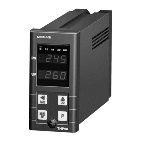
Tecnologic
Tecnologic THP 98 User manual
Tecnologic
Tecnologic TLK 48 User manual
Tecnologic
Tecnologic TLK 48 B User manual
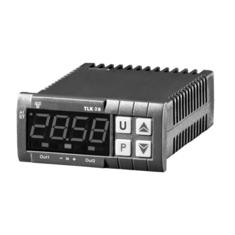
Tecnologic
Tecnologic TLK 38 User manual
Tecnologic
Tecnologic K series Operating instructions
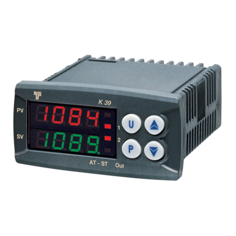
Tecnologic
Tecnologic K Series Operating instructions
Tecnologic
Tecnologic W09Y User manual
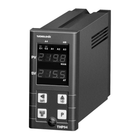
Tecnologic
Tecnologic THP 94 User manual
Tecnologic
Tecnologic TLK 94 User manual
Tecnologic
Tecnologic TLZ 11 P User manual

