DESCRIPTION
The 129 series is entirely made in AISI316L stainless steel to protect CCTV cameras in outdoor locations, especially where
corrosive environment can cause the premature deterioration of a standard aluminium plastic camera housing.
MODELS
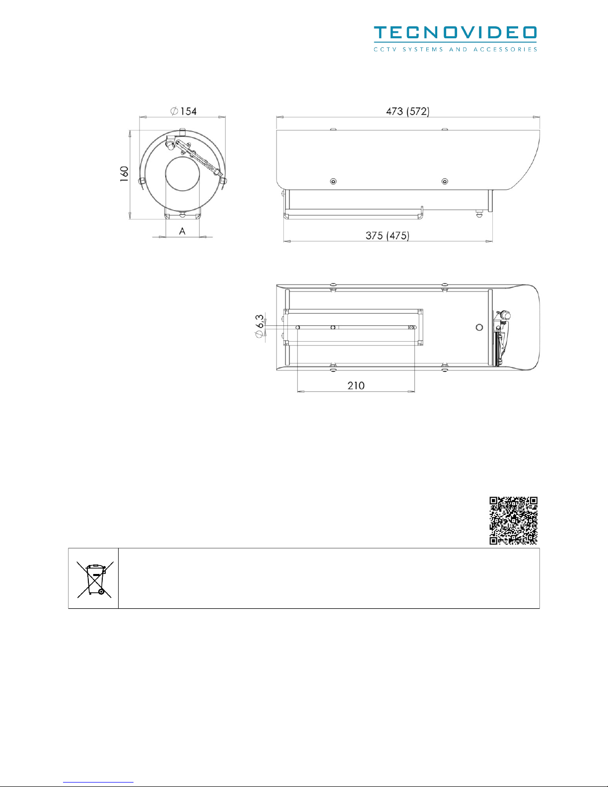
129 Camera housing (L=360 mm)
129SH Camera housing (L=360 mm) with sunshield and heater
129 Camera housing (L=360 mm) with sunshield, heater and integrated wiper
129AB Camera housing (L=360 mm) with front window air barrier. Sunshield and heater optional
129IR50 Camera housing (L=360 mm). UFW: 50 mm
129SHIR50 Camera housing (L=360 mm) with sunshield and heater. UFW: 50 mm
129 IR50 Camera housing (L=360 mm) with sunshield, heater and integrated wiper. UFW: 50 mm
129IR70 Camera housing (L=360 mm). UFW: 70 mm
129SHIR70 Camera housing (L=360 mm) with sunshield and heater. UFW: 70 mm
129 IR70 Camera housing (L=360 mm) with sunshield, heater and integrated wiper. UFW: 70 mm
129ABIR70 Camera housing (L=360 mm) with front window air barrier. Sunshield and heater optional. UFW: 70 mm
UFW: usable front window diameter
-L suffix refers to camera housing with L=460 mm
CERTIFICATIONS
Weatherproof standard: IP67
EN 61000-6-3:2007 and 50130-4:1995 + A1:1998 + A2:2003 (EMC – Electromagnetic Compatibility)
60950-1:2006 + A11:2009 (LVD – Safety)
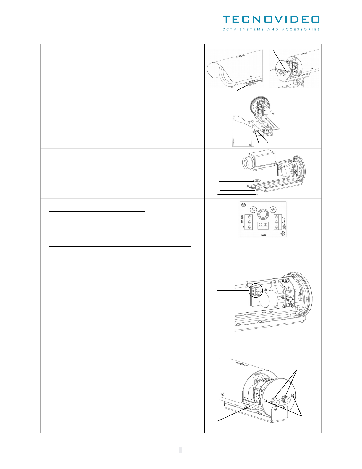
INSTALLING THE CAMERA
i
Prior to installation and operation, read carefully all instructions the in this manual and heed all warnings.
Unpack this equipment and handle it carefully. If the package appears to be damaged, notify the shipper immediately.
Use the original packaging to transport the unit. Disconnect power supply before moving it. In case of returning the equipment, the
original packaging must be used.
Make sure that the installation surface can support at least four times the weight of the unit in normal operating conditions. In case of
excessive external stress (e.g. vibration, strong winds or impact), the equipment may need additional means of protection.
Proper stainless steel hardware should be carefully chosen to fasten the unit to the surfaces.
Use caution when lifting and assembling the unit. It is recommended that non-slip protective gloves be worn during installation. The unit
could bear sharp edges.
Trying to manually force the wiper will result in damaging the device and will void the warranty.
To maintain the IP rating of the unit, adequate cable glands must be used. The unit must be tightly closed when operating.
For security reasons, do not install the unit in the proximity of water containers and never push objects or pour liquids into the unit. The
unit can be safely used in damp environments or outdoors, as long as the connectors are properly sealed.
Video and data cables should not share the same conduit with supply voltage cables. Whenever EMC is an issue, adequately shielded
cables must be used.
Open only the covers pointed out in this installation manual. Other covers should be open only by the manufacturer. Tightening loosing
the screws using automatic tools such as drill drivers may result in damaged threads.
This equipment has been designed to fit in harsh environments requiring little or no maintenance. Suggested inspection interval is 6
months, but extremely harsh environments may require more frequent inspection and maintenance checks. On each inspection check the
O-ring seals and the eventual window wiper blade integrity. Replace them if necessary.
Check cables, electrical connections and mounting hardware for integrity and tightness. Replace or tighten any damaged loose part.
Operating temperature: -20° +55° C (-4° +131° F).
h
Before performing any operation, turn off the power. The installation of the unit can be performed only by qualified personnel in
accordance with the regulations in force. Do not connect the unit to a supply circuit unless the installation is completed.
Check carefully the supply voltage marked on the label. Incorrect Power Supply Voltage may damage the unit. Do not overload the
terminal connection, as it may cause a fire or electrical shock hazard.
An all-pole mains switch with an opening distance between the contacts at least 3 mm in each pole must be incorporated in the electrical
installation. The switch must be equipped with protection against the fault current towards the ground (differential) and the overcurrent
(magnetothermal, maximum 15A). It must be very quickly recognizable and readily accessible. A suitable blow fuse must also be installed
for protection.
For connection to the mains, use a multipolar cable having minimum 3x1,5 mm2 (15 AWG). The main cable must be at least protected by an
ordinary PVC sheath.
Fasten all the cables inside the housing with cables ties or other fixing means to avoid the electrical contact with surrounding parts in case
that terminal blocks screw off.
Electrical connections (such as plugs and cords) must be protected from potential hazardous environmental factors (e.g. foot traffic, hitting
objects).
Ensure that the unit case is properly earthed, connecting all the earth ground studs. Earth cable should be about 10mm longer than the
other cables on the connector, in such way that it won't be accidentally disconnected if the cable is stretched or pulled.
When leaving the unit unused for long periods, disconnect supply cables.
2