TecnoVideo tekno system Linea 6 Series User manual

Linea 6 Series
Aluminium Camera Housings
Installation manual
Issue 20200115

TABLE OF CONTENTS
Page
DESCRIPTION 03
GENERAL & MECHANICAL 03
ELECTRICAL 03
PRELIMINARY REMARKS 03
INSTALLING THE HOUSING (KIT6A and KIT6AC) 04
INSTALLING THE HOUSING (KIT6P) 0
INSTALLING THE HOUSING (KIT6C) 06
DIMENSIONS 07
2

DESCRIPTION
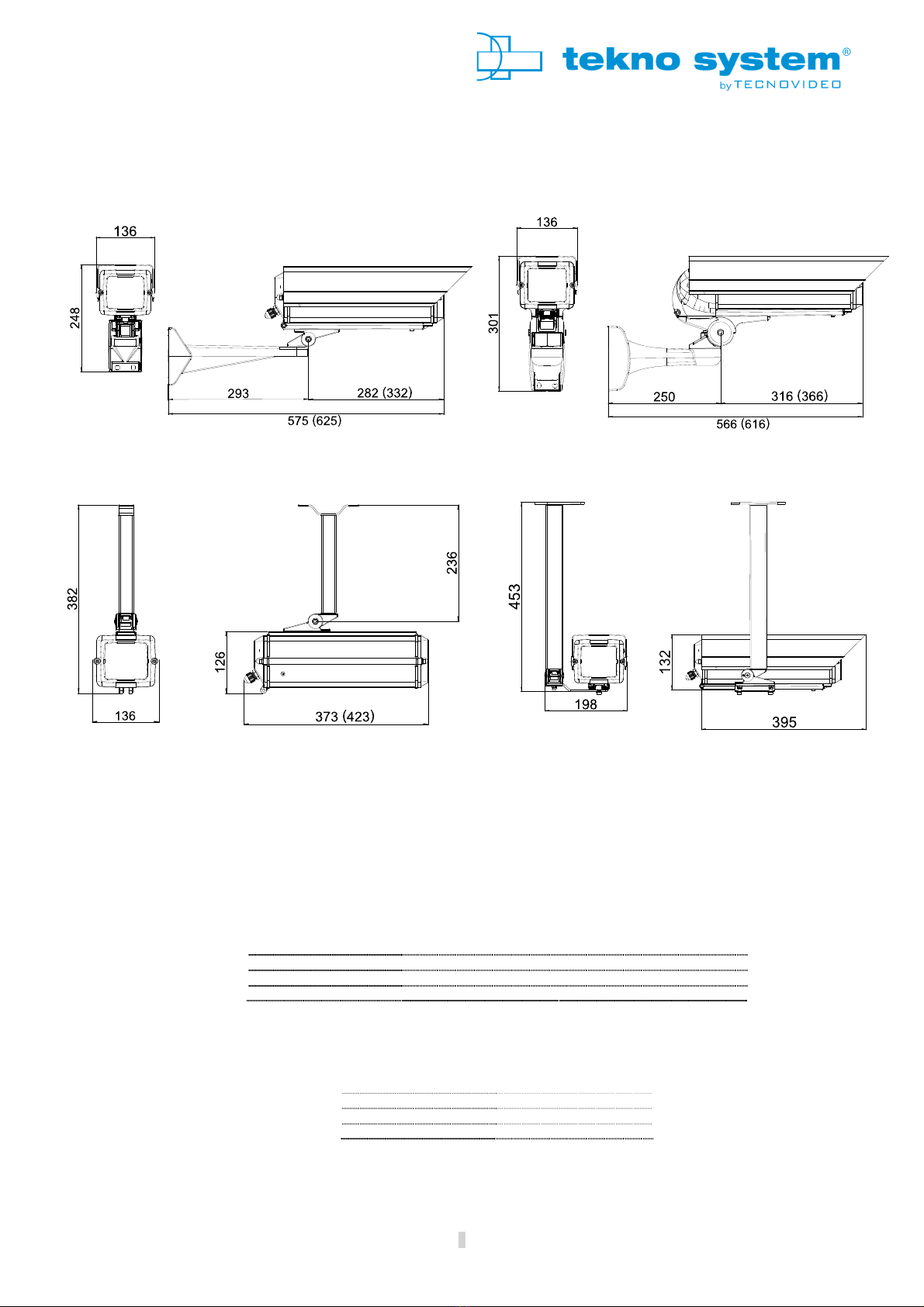
The LINEA 6 series is made of extruded and die-cast aluminium and is available in two lengths. This series allows to accommodate a vast range
of
CCTV
cameras. The exclusive slide and hang system permits easy and safe maintenance operations even in the must critical positions. Its
high quality materials guarantee exceptional reliability and durability.
Linea 6 is available in four versions according to the type of mounting bracket:
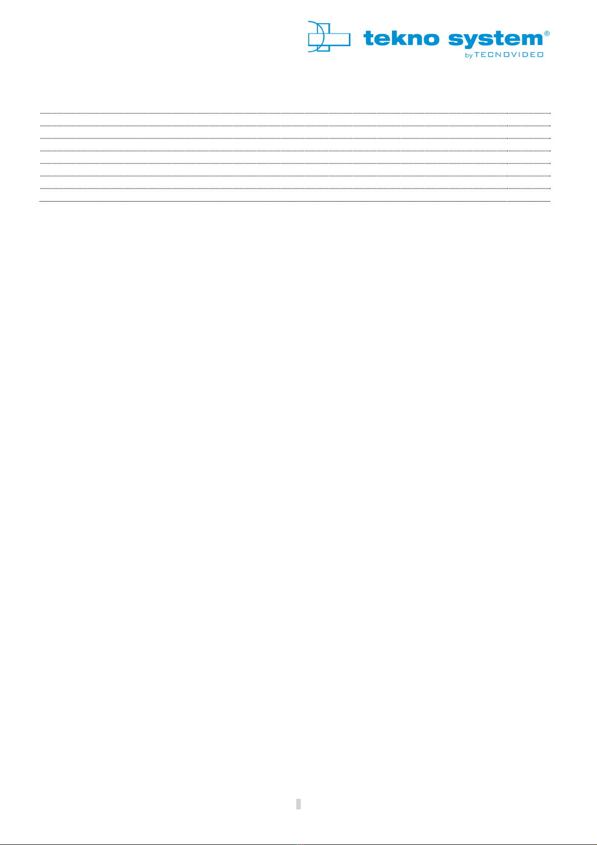
- KIT6A: wall mounting bracket version.
- KIT6P: internal cable management wall mounting version.
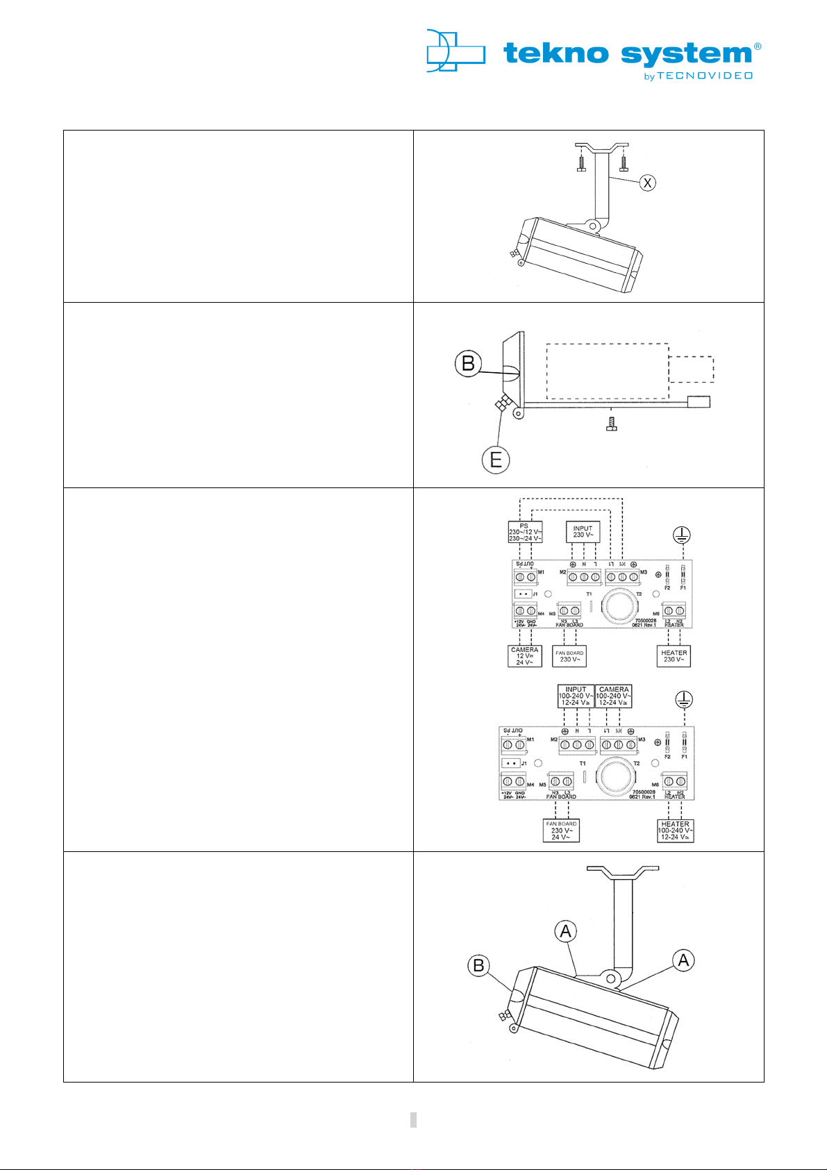
- KIT6AC: ceiling mount (side) bracket version.
- KIT6C: ceiling mount (top) bracket version.
GENERAL & ECHANICAL
Operating Temperature -20° + 0°C
Construction Extruded aluminium body and sunshield
Die cast aluminium parts
Finish RAL 9002 Polyester powder coating
Cable entries 3 M16x1, cable glands
2 M16x1, cable glands for model with fan.
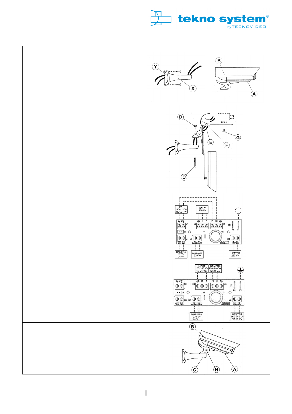
ELECTRICAL
Thermostatically controlled heater T[°C] ON = 1 ± °C, T[°C] OFF = 22 ± 4°C
Available voltages 12-24VUC, 11 -230V~
Heater power consumption 7W average, 20 W peak (12-24VUC)
10W average, 40W peak (11 -230V~)
Thermostatically controlled fan T[°C] ON = 37 ± 4°C, T[°C] OFF = 27 ± 3°C
Fan power consumption 1W
PRELI INARY RE ARKS
I
Prior to installation and operation, read carefully all instructions in this manual and heed all warnings.
Unpack this equipment and handle it carefully. If the package appears to be damaged, notify the shipper immediately.
Use the original packaging to transport the unit.
Disconnect power supply before moving it. In case of returning the equipment, the
original packaging must be used.
Make sure that the installation surface can support at least four times the weight of the unit in normal operating conditions
. In case of
excessive external stress (e.g. vibration, strong winds or impact), the equipment may need additional means of protection.
Proper hardware should be carefully chosen to fasten the unit to the surfaces.
Use caution when lifting and assembling the
unit. It is recommended that non
-
slip protective gloves be worn during installation. The unit
could bear sharp edges.
To maintain the IP rating of the unit, adequate cable glands must be used. The unit must be tightly closed when operating.
For securit
y reasons, do not install the unit in the proximity of water containers and never push objects or pour liquids into the unit.
The
unit can be safely used in damp environments or outdoors, as long as the connectors are properly sealed.
Video and data cabl
es should not share the same conduit with supply voltage cables. Whenever EMC is an issue, adequately shielded
cables must be used.
Only open the unit according to the prescriptions in this manual. Tightening/loosening the screws using automatic
tools such as drill
drivers may result in damaged threads.
Heating element has been shut off recently, it may still be hot.
This equipment has been designed to require little or no maintenance. Suggested inspection interval is 6 months, but extremel
y h
arsh
environments may require more frequent inspection and maintenance checks. On each inspection check the gaskets. Replace them
if
necessary.
Check cables, electrical connections and mounting hardware for integrity and tightness. Replace or tighten any
damaged/loose part.
h
Before performing any operation, turn off the power. The installation of the unit can be performed only by qualified personne
l in
accordance with the regulations in force. Do not connect the unit to a supply circuit unless the installation is completed.
Check carefully the supply voltage marked on the label. Incorrect Power Supply Voltage may damage the unit. Do not overload t
he
terminal connection, as it may cause a fire or electrical shock hazard.
An all
-
pole mains
switch with an opening distance between the contacts at least 3mm in each pole must be incorporated in the electrical
installation between the equipment and the main supply. Isolating switches, circuit breakers or any equivalent device can be
used as a
disconnection switch. Such switch must be very quickly recognizable and readily accessible.
Fasten all the cables inside the housing with cables ties or other fixing means to avoid the electrical contact with surround
ing parts in
case that terminal blocks screw off.
Electrical connections (such as plugs and cords) must be protected from potential hazardous environmental factors (e.g. foot
traffic,
hitting objects).
Ensure that the unit case is properly earthed, connecting all the earth ground
studs. Earth cable should be about 10mm longer than the
other cables on the connector, in such way that it won't be accidentally disconnected if the cable is stretched or pulled.
When leaving the unit unused for long periods, disconnect supply cables.
3

INSTALLING THE HOUSING (KIT6A and KIT6AC)
1. ount the bracket.
Fix the bracket (X) to the mounting surface. Loosen the
screw (A) and unscrew the two screws (B) with a 4mm
Allen key. For an easier access to the screws (B) push the
sunshield forward.
2. Open the housing.
Slide forward the housing body. Disconnect Earth cable. In
order to completely remove the body, pull the pins (C) out
of the rails (D). Feed the cables through the cable glands
(E) on the rear flange.
3. Electrical connections.
Install the camera with the provided screw and insulating
washer. Perform the electrical and video connections
according to the instructions in the camera installation
manual.
4. Close the housing.
To close the housing connect back Earth cable, slide back
the body in its original position and tighten screws (B) and
(A).
4

INSTALLING THE HOUSING (KIT6P)
1. ount the bracket.
Feed the cables through the mounting bracket (X). In
case it is needed, it is possible to remove one of the slot
covers (Y) on the mounting bracket to provide an
additional cable entry. Fix the bracket to the mounting
surface. Loosen the screw (A) and unscrew the two
screws (B) with a 4mm Allen key. For an easier access to
the screws (B) push the sunshield forward.
2. Open the housing.
a. Slide forward the housing body.
b. Disconnect Earth cable.
c. Feed the cables inside the swivel joint.
d. Fix it to the bracket with screw (C) and nut (D).
e. Pierce the needed fairleads (E). Two Ø7-9 cables
fairleads and two Ø9-12 cables fairleads are available.
Feed the cables through the fairleads. Tighten the screws
on the two plates (F)
3. Electrical connections.
Install the camera with the provided screw and insulating
washer. Perform the electrical and video connections
according to the instructions in the camera installation
manual.
4. Close the housing.
Adjust the housing position and tighten the screws (C)
and (H) with a 6mm Allen key to fix it. To close the
housing connect back Earth cable, slide back the body in
its original position and tighten screws (B) and (A).
5

INSTALLING THE HOUSING (KIT6C)
1. ount the bracket.
Fix the bracket (X) on the ceiling.
2. Open the housing.
a. Unscrew the two screws (B) with a 4mm Allen key.
b. Slide back the rear part.
c. Disconnect Earth cable.
d. Feed the cables through the glands (E).
3. Electrical connections.
Install the camera with the provided screw and insulating
washer. Perform the electrical and video connections
according to the instructions in the camera installation
manual.
4. Close the housing.
Slide back the rear part to its original position, connect
back Earth cable, tighten the two screws (B). Camera
position (back and forward) can be adjusted via the two
screws (A) with a 4mm Allen key.
6

DI ENSIONS
Dimensions in millimetres – Tolerances according QMS – Design and product specifications subject to change without notice
7
KIT6A/300 KIT6P/300
KIT6C/300
KIT6AC/300
DIMENSIONS IN BRACKETS REFER TO “LINEA 6 SERIES/350”
MAX INTERNAL USABLE AREA
odel
ax internal
dimension [mm]
ax usable
internal diameter [mm]
KIT6A/300
10 x86 264 (314)
KIT6P/300
10 x86 264 (324)
KIT6C/300 10 x86 264 (314)
KIT6AC/300
10 x86 264 (314)
MOUNTING PATTERN
odel ounting Pattern
KIT6A/300 4x Ø8 on 121x36
KIT6P/300
4x Ø8 on 121x36
KIT6C/300 2x Ø8 on 97,6
KIT6AC/300 3x Ø8 on 97,6 (triangle)

Preserve this manual as a reference for future needs.
Used electrical, electronic and
stainless steel
products should not be mixed with general waste.
For proper treatment, recovery and recycling of old products, please take them to applicable collection points, in accordance with your national
legislation and the Directives 2002/9 /EC and 2002/96/EC.
By disposing of these products correctly, you will help to save valuable resources and prevent any potential negative effects on human health and the
environment which could otherwise arise from inappropriate waste handling.
For more information about collection and recycling of old products, please contact your local municipality or your waste disposal service.
Penalties may be applicable for incorrect disposal of this waste, in accordance with national legislation.
The manufacturer declines all liability for any consequence resulting from improper installation practices, tampering or improper uses of the product.
The descriptions and illustrations contained in this manual are not binding. The manufacturer reserves the right to make any alterations deemed
appropriate for the technical, manufacturing and commercial improvement of the product, while leaving the essential product features unchanged, at
any time and without undertaking to update the present publication.
TECNOVIDEO S.r.l.
Via A. De Gasperi, 3 36030 Villaverla (VI) ITALY
Tel. +39.044 .3 0444 – Fax +39.044 .3 72 9
www.tecnovideocctv.com – info@tecnovideocctv.com
This manual suits for next models
4
Table of contents
Other TecnoVideo Camera Accessories manuals

TecnoVideo
TecnoVideo 129 Series User manual

TecnoVideo
TecnoVideo 129AC User manual

TecnoVideo
TecnoVideo SSH254 User manual

TecnoVideo
TecnoVideo 254 Series User manual

TecnoVideo
TecnoVideo SSH204 Series User manual

TecnoVideo
TecnoVideo 129 User manual

TecnoVideo
TecnoVideo 101W Series User manual

TecnoVideo
TecnoVideo 129LC Series User manual