TECOM GW5051 User manual

DIRECT ACCESS to GW5051
Installation and Configuration
Manual of GW5051
Rev: 0.2

DIRECT ACCESS to GW5051
Page: i
Table of Contents
1. INTRODUCTION ..................................................................................................1
2. HARDWARE INSTALLATION.............................................................................2
2.1. ACCESSORIES........................................................................................................... 2
2.2. CONNECTORIZATIONS ............................................................................................... 2
2.3. INDICATORS .............................................................................................................. 3
2.4. CONNECTING THE HARDWARE ................................................................................... 3
3. CONFIGURATION ...............................................................................................5
3.1. BEFORE CONFIGURATION.......................................................................................... 5
3.2. ESTABLISH THE CONNECTION .................................................................................... 5
3.3. LAN ......................................................................................................................... 6
3.4. WAN........................................................................................................................ 7
3.4.1. DATA Service Mode............................................................................................ 8
3.4.2. VoIP Service Mode............................................................................................ 15
3.4.3. Management Service Mode .............................................................................. 16
3.5. SECURITY ............................................................................................................... 18
3.6. PARENTAL CONTROL............................................................................................... 19
3.7. ROUTING ................................................................................................................ 21
3.8. DNS....................................................................................................................... 24
3.9. POWER SAVING ...................................................................................................... 25
3.10. CERTIFICATE........................................................................................................... 25
3.11. WIRELESS .............................................................................................................. 26
3.11.1. Network ............................................................................................................. 26
3.11.2. Security ............................................................................................................. 27
3.11.3. MAC Filter ......................................................................................................... 29
3.11.4. Wireless Bridge ................................................................................................. 29
3.11.5. Advanced .......................................................................................................... 30
3.11.6. Station Info ........................................................................................................ 32
3.12. VOICE..................................................................................................................... 34
3.12.1. Basic Settings.................................................................................................... 34
3.12.2. Call Features ..................................................................................................... 35
3.12.3. Dial Plan ............................................................................................................ 35
3.12.4. Audio Codec...................................................................................................... 36
3.12.5. Advanced Settings ............................................................................................ 37
3.12.6. Debug Settings.................................................................................................. 38
3.13. MANAGEMENT......................................................................................................... 40
3.13.1. Backup Settings and Restore Default Settings ................................................. 40
3.13.2. TR-069 Client ...................................................................................................... 1
3.13.3. Internet Time ....................................................................................................... 1
3.13.4. Access Control .................................................................................................... 1

DIRECT ACCESS to GW5051
Page: ii
3.13.5. Update Software.................................................................................................. 2

DIRECT ACCESS to GW5051
Page: iii
Revision Information
Revision # Description Date Author
V 0.1 First release. April 16, 2010 Ken Leng
Chris Han
V 0.2 Change the WAN configuration and WEB basic color May 10, 2010 Ken Leng
Chris Han
Regulatory statement (R&TTE)
European standards dictate maximum radiated transmit power of 100mW EIRP and frequency range
2.400-2.4835GHz; In France, the equipment must be restricted to the 2.4465-2.4835GHz frequency
range and must be restricted to indoor use.
List of national codes
1

DIRECT ACCESS to GW5051
Page 1
1. Introduction
GW5051 wireless VoIP gateway provides you the cost-effective and integrated voice
and high-speed data access. Together with IEEE 802.11b/g, GW5051 provides
wireless mobility. Power Sourcing Equipment (PSE) over WAN interface provides
indoor For small enterprise and home
office, you are able to experience the quality voice over IP service and data
connection with most convenient wireless broadband access solution.
The Users Manual shows you the installation and the configurations of the GW5051
Features
PSE over WAN interface
10/100Base-T Ethernet router to provide Internet connectivity to all computers
on your LAN
VoIP which supports SIP protocol (RFC3261)
Support IEEE 802.11b/g WLAN
Network configuration through DHCP
PPPoA / PPPoE
NAT / NAPT
Web-based configuration browser such as Microsoft IE, Netscape Navigator,
Mozilla Firefox, etc.
System Requirements
Along with GW5051, you also need the following equipments or services before
installation.
Indoor unit which provides broadband connection and
GW5051.
Computers which equips at least an Ethernet 10Base-T/100Base-T network
interface card (port) or 802.11b/g/n WLAN card / adapter.
A web browser, such as Microsoft Internet Explorer (V5.0 or later version) or
Netscape Navigator (V4.7 or later version), which is used to configure the
GW5051.

DIRECT ACCESS to GW5051
Page 2
2. Hardware Installation
2.1. Accessories
Upon opening the gift box of GW5051 wireless VoIP gateway, you will find following
parts in the box.
GW5051 x 1
Power adapter x 1
Power core x 1
Ethernet cable x 1
Telephone cable x 2
Quick Installation Guide x 1
2.2. Connectorizations
All the connectors, reset button power switch and power jack are on the rear panel
whose picture is shown below.
Picture / diagram are to be inserted here.
The functions of the connectors are described in following table.
Label Color Function
POWER BLACK Connect to power adaptor.
ON / OFF BLACK Turn on / off power.
RESET BLACK Shortly push RESET button to restart the device.
Long press RESET button to reset the configuration to factory
default and restart the device.
WAN SILVER Connect modem with 8P8C RJ45 cable. It
also provide power to outdoor modem.
LAN1 ~
LAN4
YELLOW RJ-45 connectors, connect the device to your PC's Ethernet
port, or to the uplink port on your LAN's hub or home gateway,
using the Ethernet cables.
VoIP1 ~
VoIP2
BLACK RJ-11 connectors, connect the device to regular phones.

DIRECT ACCESS to GW5051
Page 3
2.3. Indicators
All LED indicators are on front panel which is shown below. Their functions are listed
in following table.
Picture / diagram are to be inserted here.
Label Color Function
POWER Light-Green Steadily off: Power is off.
Solid on: Power on
WLAN Light-Green
Steadily off: Wi-Fi is disabled.
Blinking: Traffic is passing thru.
Steadily on: Wi-Fi is activated.
VoIP1 ~
VoIP2 Light-Green Steadily off: Regular phone is on hook.
Solid on: Regular phone is off hook.
LAN1 ~
LAN4 Light-Green
Steadily off: Wired interface not established (Ethernet cable not
detected or not connected properly).
Blinking: Traffic is passing thru.
Steadily on: Wired interface established (Ethernet cable detected).
WAN Light-Green
Steadily off: Wired interface not established (Ethernet cable not
detected or not connected properly).
Blinking: Traffic is passing thru.
Steadily on: Wired interface established (Ethernet cable detected).
2.4. Connecting the Hardware
You have to follow the steps to connect GW5051 to all the peripherals. The diagram,
shown below, depicts the generic connections of all equipments. It might be different
from the picture below which depends on your applications.
WARNING
Power off all the devices before connecting them. They
include the computer(s), LAN hub / switch (if applicable), and the
GW5051.
Picture / diagram are to be inserted here.
Step 1. Connect the indoor unit

DIRECT ACCESS to GW5051
Page 4
Connect WAN interface of GW5051 and LAN port of indoor unit
using Ethernet cable. Please be well noted that the line must be xDSL subscribed.
Step 2. Connect the Telephone
Connect regular phone and VoIP interface of GW5051 using telephone line.
Step 3. Connect the PC
Connect the yellow cable to the ETH0 / ETH1 jack (yellow one) and plug the other
end to WAN port of your PC or hub.
Step 4. Connect the Power Adaptor
Connect plug of the power adaptor to the power jack (black one) of GW5051 then
connect the plug of power core to the outlet on the wall or power strip. Power on
GW5051.
WARNING
In order for the safety, please don’t use the power adaptor which
is not we provide.
Step 5. Turn on your PC.
Power on your PC and hub if there is any.
Step 6. Configure GW5051
Configure GW5051 through the web browser on your PC. The detailed procedures
shall be described in Chapter 3.
Step 7. Save the configurations and reboot
It is important to save all the configurations you set and reboot again to affect all the
programming items.

DIRECT ACCESS to GW5051
Page 5
3. Configuration
3.1. Before Configuration
Before configuration, you have to connect and power on GW5051 and PC according
to the steps described in Chapter 2. The default IP address of GW5051 is
“192.168.1.1” and the default port number is 80.
3.2. Establish the Connection
Enter the IP address and Port (default is 192.168.1.1:80) on your web browser. A
dialogue box is popped up and request to ether the user name and password.
(Figure 3-2-1)
Figure 3-2-1. Authentication
Please use the default user name and password, “admin” and “admin”, and click OK
button to login into the system.
Once authentication process is verified, the home page “Device Info” is shown on
your browser. (Figure 3-2-2)
DIRECT ACCESS to GW5051
Page 6
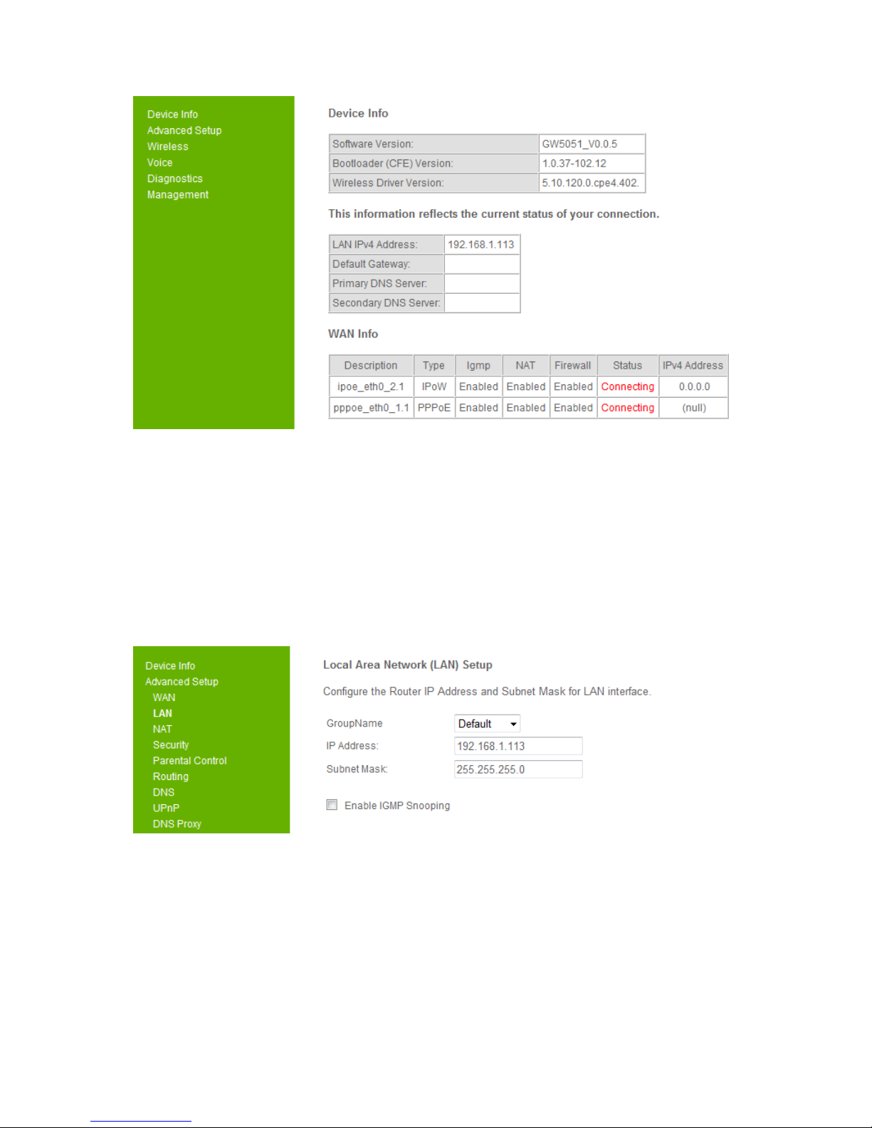
Figure 3-2-2. Device Info Page
In “Device Info” page, it shows you the basic information about the equipment, such
as software version, MAC address, serial number, as well as runtime information like
Memory usage ratio, time from last reboot. Also it will show information of the xDSL
connection and WAN connection
3.3. LAN
Click the “Advanced Setup/LAN” button on the left hand side to enter into the
configuration of LAN.
DIRECT ACCESS to GW5051
Page 7
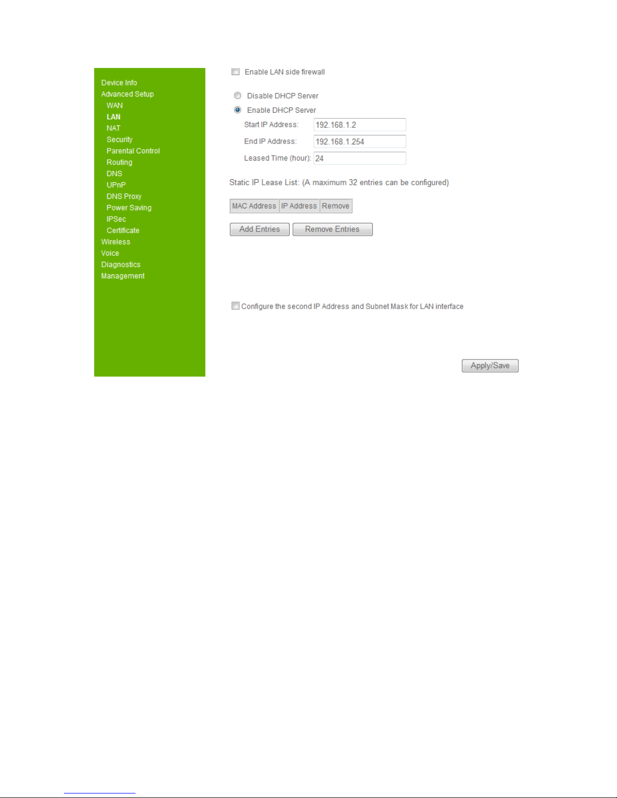
Figure 3-3. LAN
In this page, you may program the IP address of LAN, its Subnet Mask and the MTU
(Maximum Transmission Unit). You may check or uncheck the “Enable IGMP
Snooping”. There are two modes to be selected once you check this item.
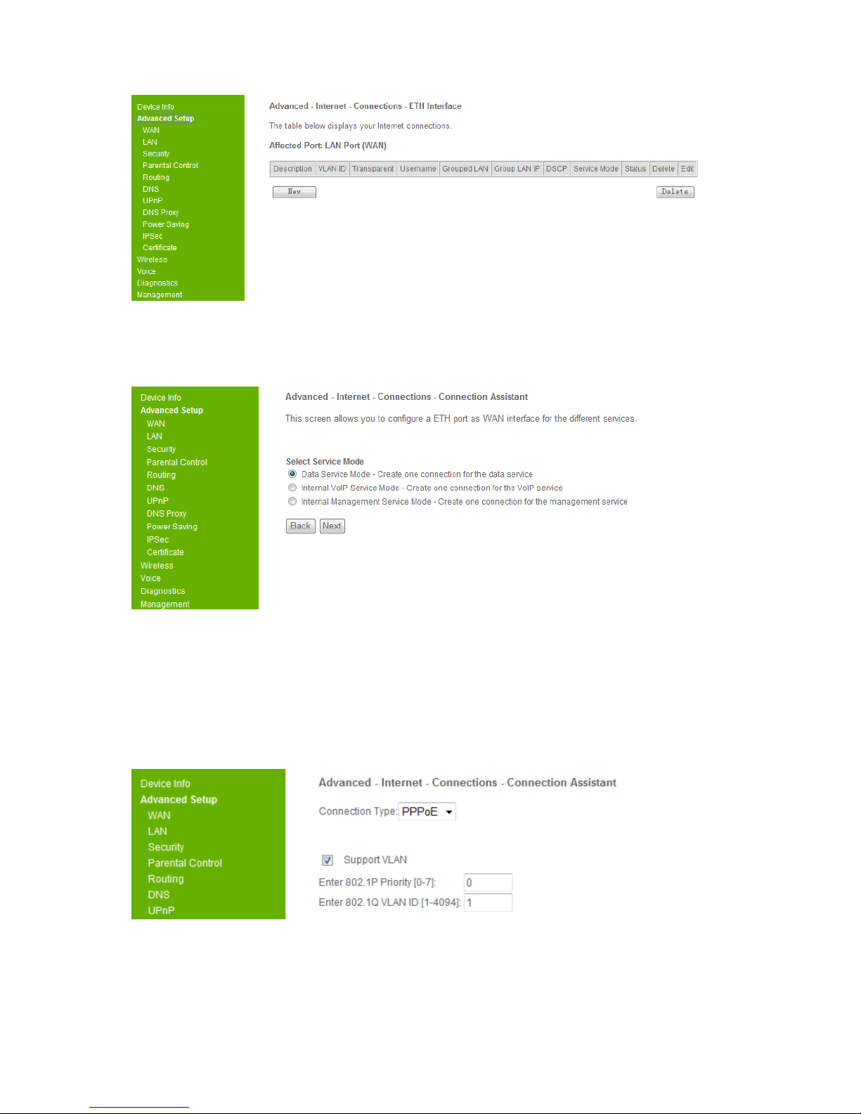
Additionally, you may also disable or enable the DHCP server and related setting of
DHCP server.
At the bottom of this page, you may check “Configure the second IP address and
subnet mask for LAN interface” to setup additional LAN interface. Please be well
noted that this IP address is used for management purpose only.
Before you leave, please click “Apply/ Save” button to save the changes you made.
3.4. WAN
Click the “Advanced Setup/ WAN” button on the left hand side of the web page to
enter into the WAN configuration.
DIRECT ACCESS to GW5051
Page 8
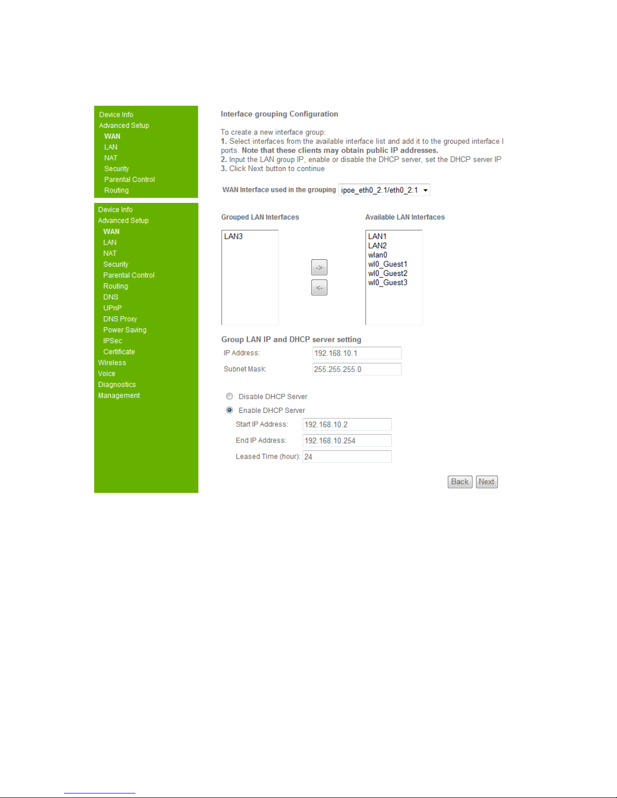
Figure 3-4. WAN Connection
Click the “New” button to create the WAN connection.
Figure 3-4. WAN Connection - 2
The detailed descriptions of each Service Mode are depicted forward.
3.4.1. DATA Service Mode
The DATA Service Mode allows you to create one connection for the data service.
Select it and click the “Next” button, it will show

DIRECT ACCESS to GW5051
Page 9
Figure 3-4-1. WAN – Data service Interface-PPPoE-1
Select your connection type, PPPoE and IPoE is for route mode, Bridge is for bridge
mode.
If you select PPPoE connection type, please enter your username and password.
For advanced user, you can customize 802.1P priority, 802.1Q VLAN ID, DSCP
value, dial on demand, disconnection time, static IP address, firewall, IGMP and LAN
PPPoE service.
And then click the “Next” button.

DIRECT ACCESS to GW5051
Page 10
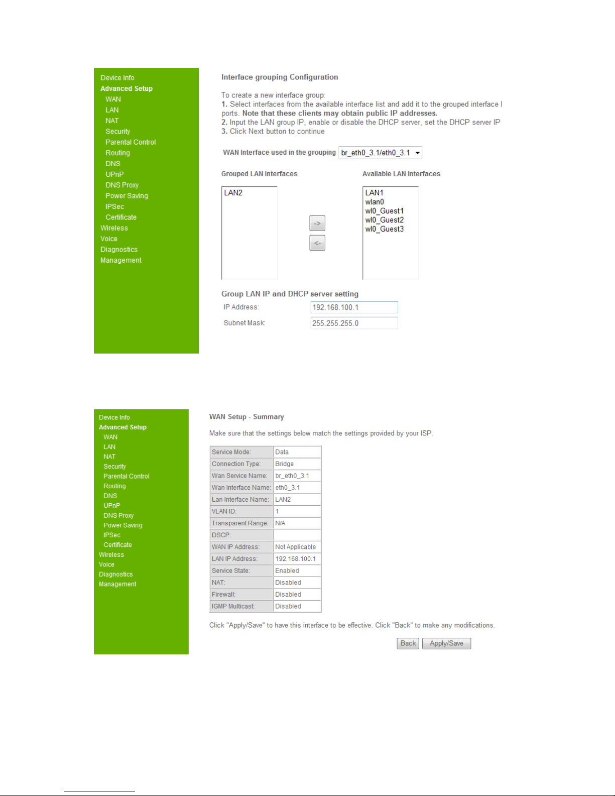
Figure 3-4-1. WAN – Data service Interface-PPPoE-2
The “WAN interface used in the grouping” shows the wan interface description name.
You can select the available Lan interfaces in the right list, and press “<-” button to
move the select interface to the grouped Lan interfaces, you also can use “->” button
to remove the select interface from the grouped Lan interfaces. Then you can set the
group LAN IP address and the settings about DHCP server on this group LAN.
You must select one Lan interface at least to group with this wan interface and click
the “Next” button.

DIRECT ACCESS to GW5051
Page 11
Figure 3-4-1. WAN – Data service Interface-PPPoE-3
Click the “Apply/Save” button to create the PPPoE wan data interface.
Figure 3-4-1. WAN – Data service Interface-IPoE-1
If you select IPoE connection type, set the VLAN and DSCP configuration.
For advanced user, you can customize firewall, IGMP, Nat and DHCP client.
DIRECT ACCESS to GW5051
Page 12
And then click the “Next” button.
Figure 3-4-1. WAN – Data service Interface-IPoE-2
You must select one Lan interface at lease to group with this wan interface and click
the “Next” button.

DIRECT ACCESS to GW5051
Page 13
Figure 3-4-1. WAN – Data service Interface-IPoE-3
Click the “Apply/Save” button to create the IPoE wan data interface.
Figure 3-4-1. WAN – Data service Interface-Bridge-1
If you select Bridge connection type, you can set this bridge to support VLAN or
support Transparent, but one interface can not support these two functions at the
same time.
For advanced user, you can customize the supported VLAN ID or the transparent
VLAN ID range, DSCP value.
And then click the “Next” button.
DIRECT ACCESS to GW5051
Page 14
Figure 3-4-1. WAN – Data service Interface-Bridge-2
You must select one Lan interface at lease to group with this wan interface and click
the “Next” button.
Figure 3-4-1. WAN – Data service Interface-Bridge-3
Click the “Apply/Save” button to create the Bridge wan data interface.
DIRECT ACCESS to GW5051
Page 15
3.4.2. VoIP Service Mode
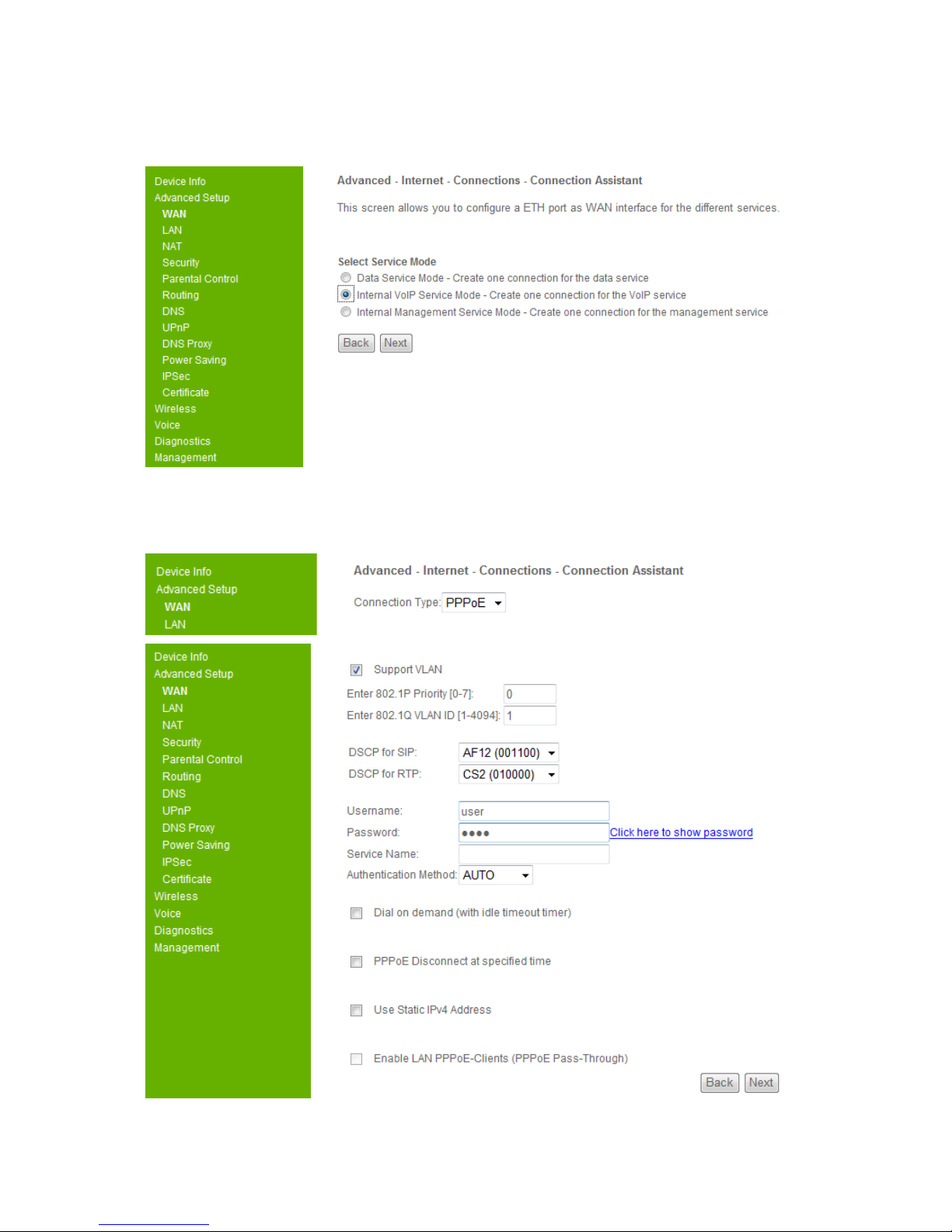
Figure 3-4-2. WAN – VoIP service Interface -1
The VoIP Service Mode allows you to create one connection for the VoIP service.
Select it and click the “Next” button, it will show
DIRECT ACCESS to GW5051
Page 16
Figure 3-4-2. WAN – VoIP service Interface -2
For the VoIP service mode, the wan connect type is only available for PPPoE and
IPoE.
For advanced user, you can customize the supported VLAN ID, DSCP for SIP,
DSCP for RTP, the advanced PPPoE settings or the advanced IPoE settings.
And then click the “Next” button.
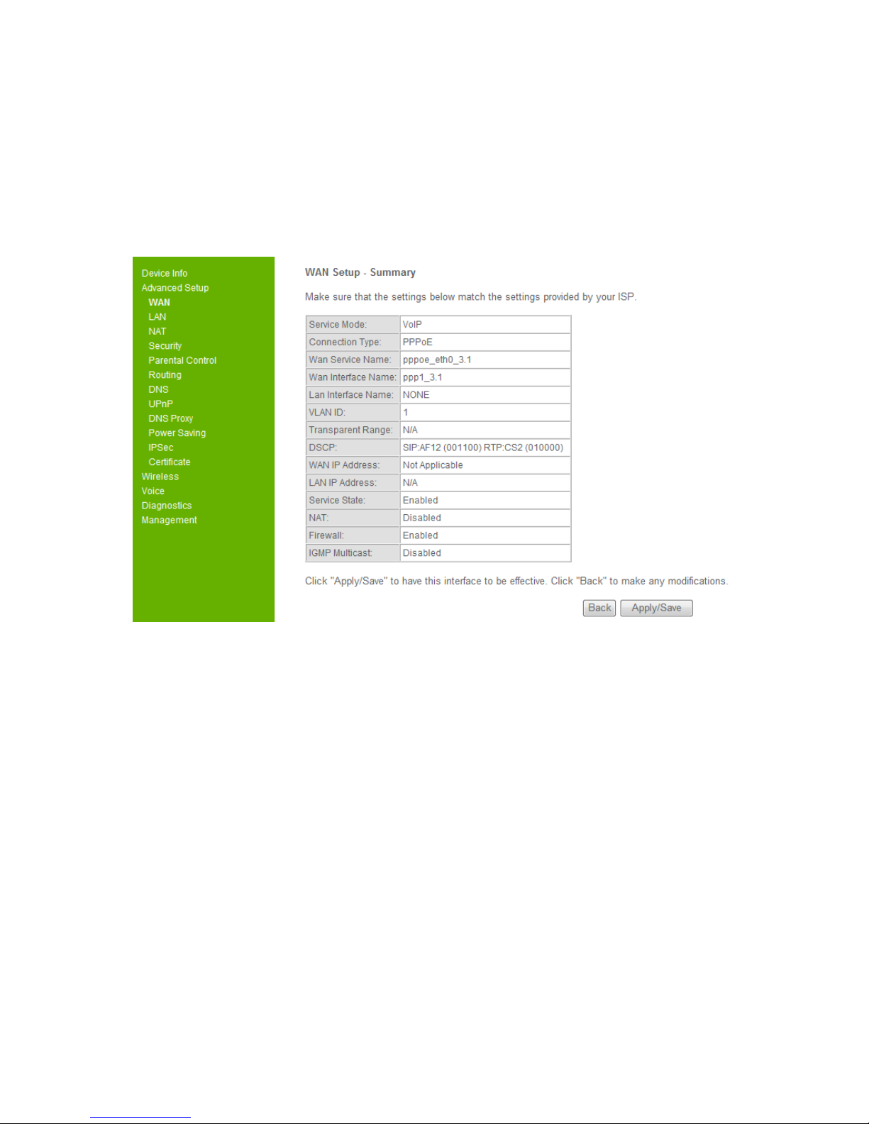
Figure 3-4-2. WAN – VoIP service Interface -3
Click the “Apply/Save” button to create the VoIP service interface.
3.4.3. Management Service Mode
Table of contents
Other TECOM Gateway manuals


Popular Gateway manuals by other brands

KeriSystems
KeriSystems MS-7000 SuperStar quick start guide

AirLive
AirLive RS-2500 user manual

Peripheral Electronics
Peripheral Electronics IPOD PGHSB1 owner's manual

Uni-Fi
Uni-Fi Security Gateway Pro manual

3One data
3One data GW1102 Series Quick installation guide

Good Way
Good Way Z-Gate FG2200 user manual


seeed studio
seeed studio BeagleBone Green reference guide

Multitech
Multitech MULTIVOIP MVP-2410 user guide

QUANTUM X
QUANTUM X CX27 operating manual

ZyXEL Communications
ZyXEL Communications PX7511-B0 user guide

Dell
Dell Dell Edge Gateway 3002 Specifications

TRI02SYS
TRI02SYS EnOcean 02LINE Installation and operating manual