TECOM AG-300 Plus2 User manual

Copyright © 2017, All Rights Reserved.
Ver: R01 D/C: 106-1121
AG-300 Plus2
Gateway
Operation Manual

Federal Communications Commission (FCC) Statement
Statement shall be listed in the label
(if the product is smaller than palm size, it could be listed in user manual for instead.)
This device complies with Part 15 of the FCC Rules.
Operation is subject to the following two conditions:
1) this device may not cause harmful interference and
2) this device must accept any interference received, including interference that may cause
undesired operation of the device.
Statement shall be listed in the manual
15.21
You are cautioned that changes or modifications not expressly approved by the part responsible
for compliance could void the user’s authority to operate the equipment.
15.105(b)
This equipment has been tested and found to comply with the limits for a Class B digital device,
pursuant to part 15 of the FCC rules. These limits are designed to provide reasonable protection
against harmful interference in a residential installation. This equipment generates, uses and can
radiate radio frequency energy and, if not installed and used in accordance with the instructions,
may cause harmful interference to radio communications. However, there is no guarantee that
interference will not occur in a particular installation. If this equipment does cause harmful
interference to radio or television reception, which can be determined by turning the equipment off
and on, the user is encouraged to try to correct the interference by one or more of the following
measures:
-Reorient or relocate the receiving antenna.
-Increase the separation between the equipment and receiver.
-Connect the equipment into an outlet on a circuit different from that to which the receiver is
connected.
-Consult the dealer or an experienced radio/TV technician for help.
This device complies with Part 15 of the FCC Rules. Operation is subject to the following
two conditions:
1) this device may not cause harmful interference and
2) this device must accept any interference received, including interference that may cause
undesired operation of the device.
FCC RF Radiation Exposure Statement:
This equipment complies with FCC RF radiation exposure limits set forth
for an uncontrolled environment. This equipment should be installed and
operated with a minimum distance of 20 centimeters from your body.
USB Port only connection Vibration gauge (VB-200STU)

Tecom AG-300 Plus2 IoT Gateway Operation Manual
Table of contents
Overview ............................................................................................................................................3
AG-300 Plus2 Confi uration ........................................................................................................5
1. System structure ..............................................................................................................5
2. Equipment wirin ............................................................................................................5
3. RS485 wirin .....................................................................................................................7
4. Power bank wirin ...........................................................................................................8
5. Equipment dimension....................................................................................................8
6. AG-300 Plus2 view...........................................................................................................9
Equipment setup............................................................................................................................10
1. Network setup................................................................................................................10
2. Account setup.................................................................................................................12
3. VB200 setup ....................................................................................................................14
4. Wireless setup ................................................................................................................17
4.1 The wireless AP mode confi uration (WiFi mode setup) .........................17
4.2 WiFi mode settin ................................................................................................22
5. Hardware setup..............................................................................................................26
APP software operation...............................................................................................................27

Tecom AG-300 Plus2 IoT Gateway Operation Manual
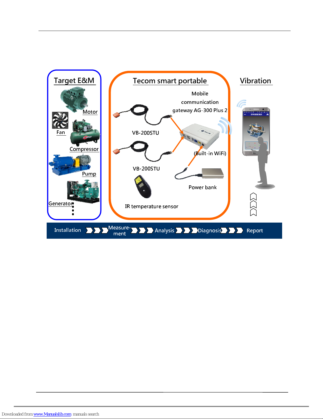
Overview
Tecom smart portable vibration diagnosis instrument is one of the most innovative
mobile maintenance products in the world. By making the most of IoT, sensor, and
management software technology it is designed to measure vibration of running E&M
e uipment without extra power cord or network cable. With fully PnP based
convenience, it is ideal for small and medium size manufacturers and enterprises in
pursuing productivity 4.0.
Featuring IoT WiFi gateway (AG-300 Plus2), integrated vibration gauge VB-200STU, IR
temperature sensor, power bank, and iOS and Android platform available diversified
smartphone APP (which can be downloaded, installed, and used immediately), Tecom
smart portable vibration diagnosis instrument system is ideal for e uipment
installation or maintenance engineers for measuring temperature and vibration at
e uipment power contact, E&M, rotary machinery, and motor on the spot. In addition,
it combines measurements made on site with interactive analysis and diagnosis of the
system to provide instant, helpful, and effective target E&M e uipment health analysis
which, in turn, not only enable easy manufacturing E&M e uipment management and
upkeep in healthy status but also prevent hazardous system shutdown from
happening.
Tecom smart portable vibration diagnosis instrument may connect up to 4 vibration
gauges for multiple diagnosis at the same time. With a breakthrough in vibration
measurement concept, it integrates vibration measurement, analysis, and diagnosis
operation in one portable device to save working hours and reduce onsite
maintenance and repair time significantly.
Tecom smart portable vibration diagnosis instrument system may help ac uiring full
first commissioning operation data that is critical for later maintenance and big data
analysis for manufacturer in future product release.

Tecom AG-300 Plus2 IoT Gateway Operation Manual
In situ and instant vibration dia nosis information
Productivity 4.0
Tecom AG-300 Plus2 IoT Gateway Operation Manual
AG-300 Plus2 Configuration
1.
System structure
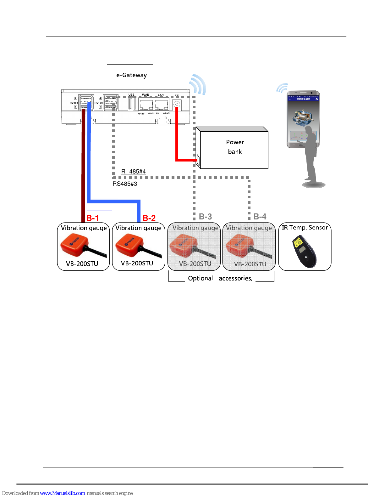
2.
Equipment wiring
Open portable vibration dia nosis instrument carrying case and belt, and connect
them according to wiring diagram shown below.
A. Connect AG-300 Plus2 to VB-200STU with RS485(1/2)
B. Connect AG-300 Plus2 DC Jack to power bank to the power cord
C. WiFi connect smartphone to built-in WiFi router of AG-300 Plus2
D. Mount (magnetic) vibration gauge to target e uipment according to its installation
guidelines
IR temperature
sensor
VB-200STU
VB-200STU
Mobile
communication
gateway AG- 00 Plus 2
Power bank
Tecom smart portable
Target E&M
Motor
Compressor
Fan
Gen
erator
Pump
(Built-in WiFi)
Vibration
Installation
Measure-
ment
Analysis
Diagnosis
Report
Tecom AG-300 Plus2 IoT Gateway Operation Manual
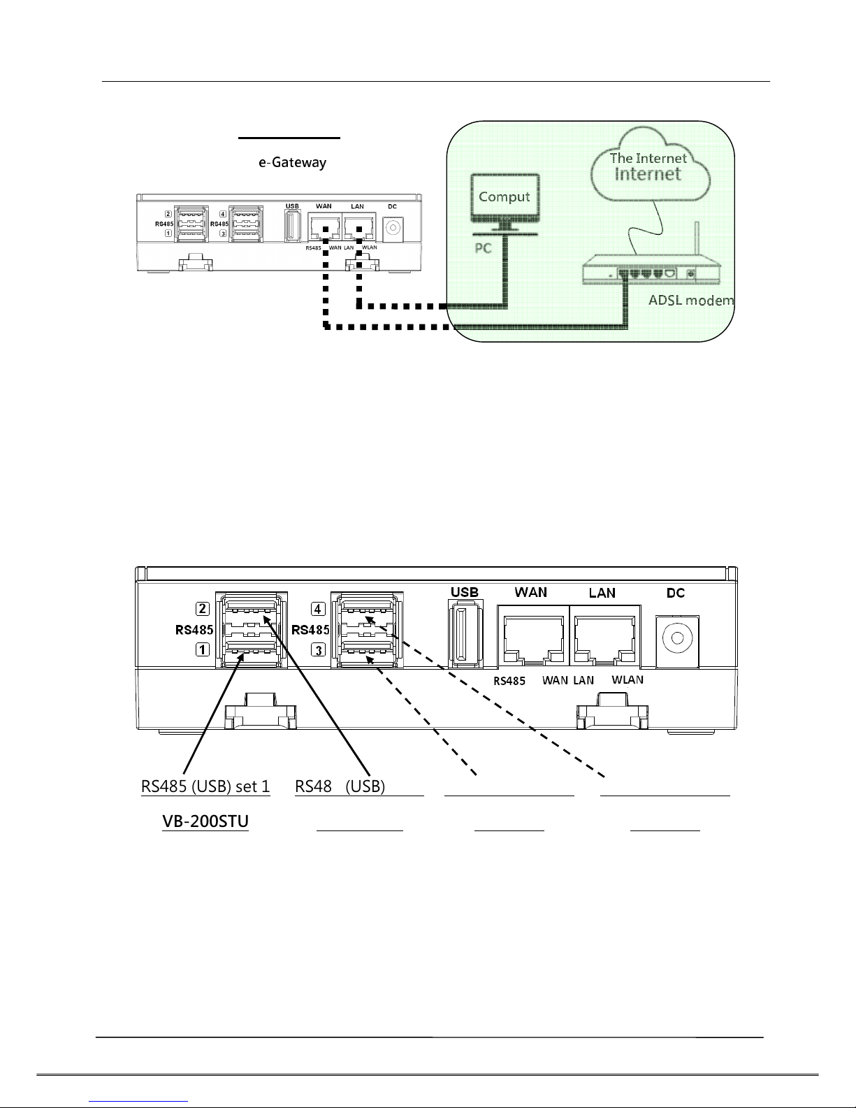
Once wired according to aforementioned diagram, your smartphone is now ready to
execute test, analysis, and diagnosis over target e uipment with the "vibration
diagnosis" APP; follow the following diagram and steps E~F for computer and the
Internet connection as re uired.
E. Connect AG-300 Plus2 WAN port (blue) and LAN port of ADSL modem with
network cable
F. Connect AG-300 Plus2 LAN port (yellow) and PC with network cable (for system
setup only)
RS485#1
RS485#2
A
B
C
RS485
AG-300 Plus2
e-Gateway
VB-200STU
Vibration
g
auge
VB-200STU
Vibration gauge
VB-200STU
Vibration gauge
VB-200STU
Vibration gauge IR Temp. Sensor
Power
bank
RS485#3
RS485#4
Optional accessories,
B-1
B-2
B-3
B-4
Tecom AG-300 Plus2 IoT Gateway Operation Manual
3.
RS485 wiring
(1) AG-300 Plus2
E-gateway AG-300 Plus2 supports up to 4 vibration gauge with RS485 (USB)
connection as shown in figure below:
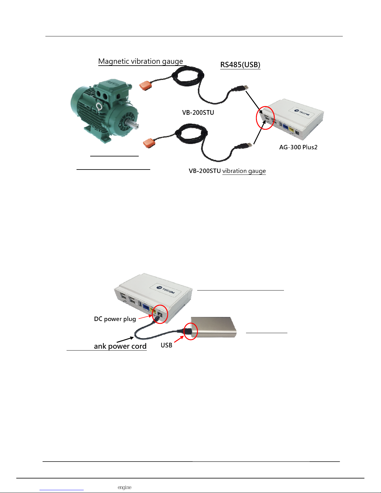
(2) VB-200STU
This portable vibration diagnosis instrument comes with 2 built-in vibration gauges
VB-200STU; featuring integrated RS485 cable and USB connector the latter may direct
connect to e-gateway AG-300 Plus2 as shown inthe figure below:
A
B
C
RS485
C
A
AG-300 Plus2
ADSL modem
The Internet
e-Gateway
Comput
RS485 (USB) set 1
VB-200STU
RS485 (USB) set 2
VB-200STU
RS485 (USB) set 3
Reserved
RS485 (USB) set 4
Reserved
Tecom AG-300 Plus2 IoT Gateway Operation Manual
4.
Power bank wiring
This portable vibration diagnosis instrument comes with power bank power cord,
please connect DC Plug to DC jack of AG-300 Plus2 and USB connector to USB port in
power bank as shown in figure below:
5.
Equipment imension
AG-300 Plus2 dimension: 130mm (length) x 90mm (width) x 36 mm (height)
VB-200STU
VB-200STU
vibration gauge
RS485(USB)
Magnetic vibration gauge
AG- 00 Plus2
Target E&M
equipment (motor)
Power bank power cord
Power bank
e- ateway AG-300 Plus2
DC power plug
USB

Tecom AG-300 Plus2 IoT Gateway Operation Manual
6.
AG-300 Plus2 view
Tecom AG-300 Plus2 IoT Gateway Operation Manual
Equipment setup
1.
Network setup
Step 1
- Keep your PC / NB and e-gateway AG-300 Plus2 in the same LAN segment
(better have DHCP enabled on your PC / NB)
- Connect PC/NB and AG-300 Plus2 (LAN port) with Ethernet cable
- Connect power adaptor to AG-300 Plus2
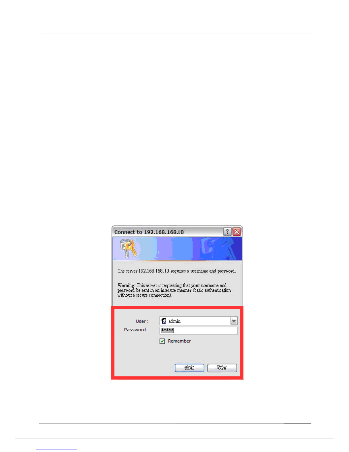
- Open a browser on the connection, input AG-300 Plus2 setup page address
http://192.168.168.10
- Input user name: admin
- Input password: IP585xAdmin
- Click OK
Tecom AG-300 Plus2 IoT Gateway Operation Manual
Step 2
(Skip this step for DHCP PnP network)
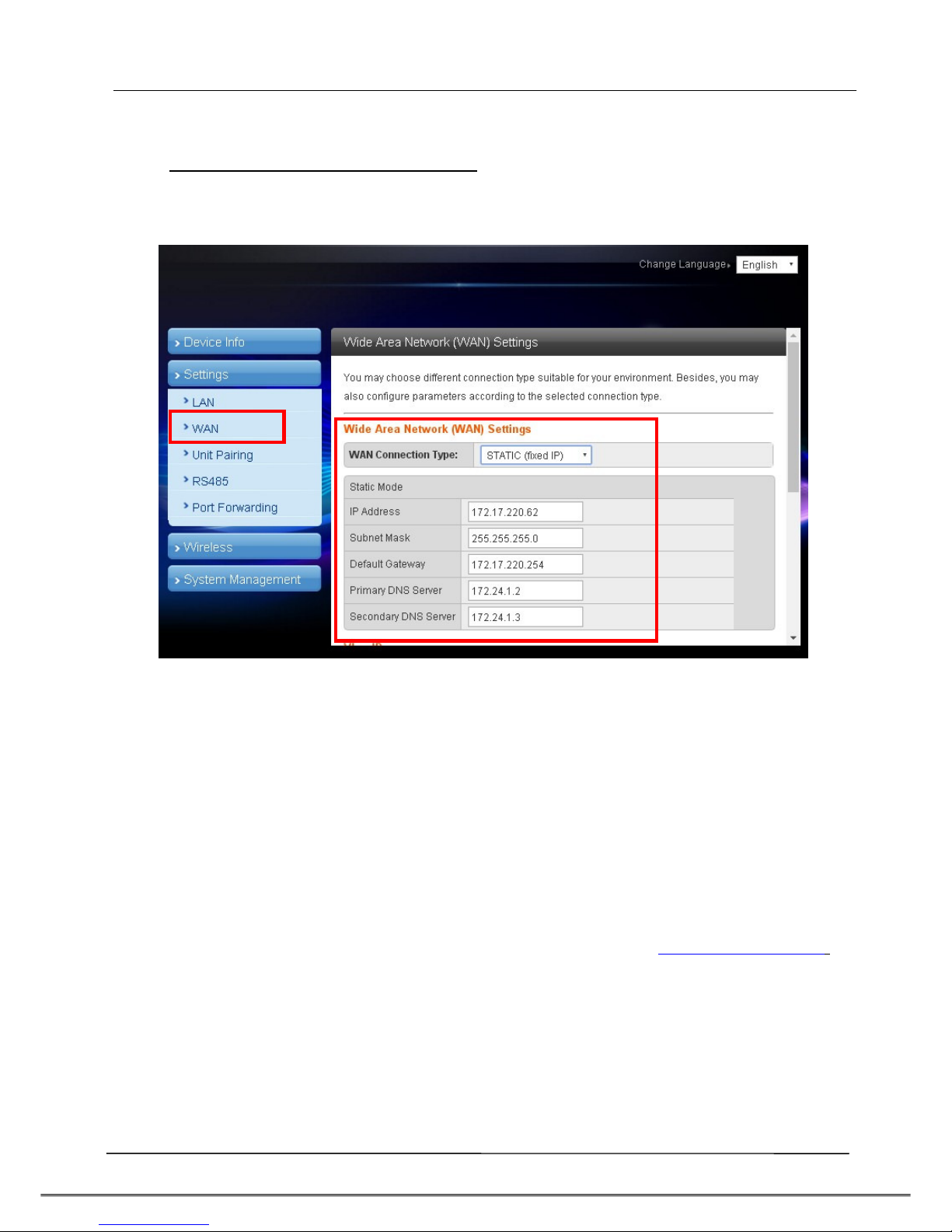
- In main menu on the left, click [Settin s] [WAN].
- In WAN connection type dropdown menu, select [STATIC (Fixed IP)]
- IP address: input IP data.
- Subnet mask: input subnet mask data.
- Default ateway: input default gateway data.
- Primary DNS server: input main DNS server data.
- Secondary DNS serverinput secondary DNS server.
- Click the [Apply] button at bottom of page once all settings were made
successfully.
Try connectin to popular web sites (e. ., edition.cnn.com and www.yahoo.com.tw
to validate external networkin function
Set smartphone APP communication port to TCP 53100 ~53199 in case firewall
mana ement service is in existence.
Tecom AG-300 Plus2 IoT Gateway Operation Manual
2.
Account setup
Step 1
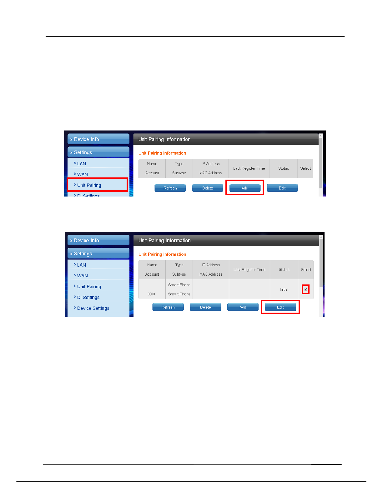
In main menu on the left, click [Settin s] [Unit pairin ] before selecting [Add]
button.
Step 2
Check the [Select] column before selecting the [Edit] button
Tecom AG-300 Plus2 IoT Gateway Operation Manual
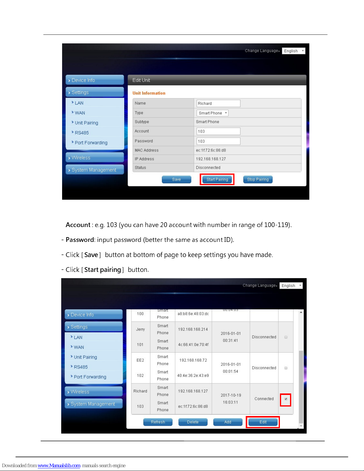
- Name : input user name.
-
Account
: e.g. 103 (you can have 20 account with number in range of 100-119)
.
-
Password
: input password (better the same as account D)
.
-
Click
[
Save
]
button at bottom of page to keep settings you have made.
-
Click
[
Start pairing
]
button
.

Tecom AG-300 Plus2 IoT Gateway Operation Manual
- To edit user account: check the [Select] column; click the [Edit] button, and the
existing settings of the account displays for you to change.
- To delete user account: when the user was disconnected check the [Select]
column, click the [Delete] button to remove the account.
3.
VB200 setup
This portable vibration diagnosis instrument supports up to 4 magnetic VB-
200ST(U)/VB-200SC for concurrent measurement, analysis, and diagnosis; see
section "RS485 wiring" for its installation.
The VB-200 series vibration gauge comes with default value of RS485 ID at 15; one
RS485 cable may connect one VB-200 series vibration gauge only; factory default
of this portable vibration diagnosis instrument may connect two VB-200 series
vibration gauge; please connect the latter to the 1st and 2nd RS485 port of AG-
300 Plus2; the 3rd and 4th RS485 ports are reserved for expansion in the future; to
connect 3 or more VB-200 series vibration gauge you need to add RS485 device in
the management page first.
Connect only one VB-200 series vibration gauge in a RS485 port, otherwise the
system may fail to identify individual gauge as each of them bears the same
RS485 ID value of 15; please make sure only one VB-200 series vibration gauge is
connected to one RS485 port to prevent setup confusion.
Please follow steps below to add the 3rd VB-200 series vibration gauge:
- In main menu on the left, click [Settin s] [RS485].
- The VB200 page displays and click [Add]
option in it.

Tecom AG-300 Plus2 IoT Gateway Operation Manual
- Name: "VB-200" or any name you like.
- Line: select line 3 ~ 4 (line 1~2 added by factory default).
- RS485 ID: please fill in a value compliant with your RS485 configuration (this
system support RS485 ID in range of 0-15).
- Click [Save] button at bottom of page.

Tecom AG-300 Plus2 IoT Gateway Operation Manual
- To edit the settings of VB-200: check the [Select] column, click the [Edit] button,
and the existing settings display for you to change.
- To delete settings of VB-200: check the [Select] column, click the [Delete] button
to remove the VB-200 vibration gauge.
- To add VB-200 vibration gauge: click the [Add] button to add new VB-200 setup.
Tecom AG-300 Plus2 IoT Gateway Operation Manual
4.
Wireless setup
Designed for e-gateway AG-300 Plus2 hardware, the "wireless setup" page
contains options of WiFi mode, "Basic", "Advanced", "Security", and "Station list".
You may set WiFi mode into "Wireless AP mode" and "Wireless client mode".
The wireless AP mode is an AP with gateway serving as WiFi access point.
The wireless client mode set the gateway as a client to connect to other WiFi AP.
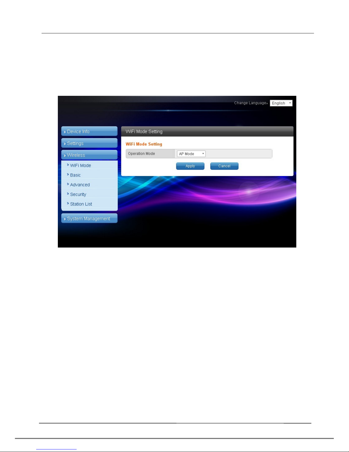
4.1 The wireless AP mode confi uration (WiFi mode setup)

Tecom AG-300 Plus2 IoT Gateway Operation Manual
4.1.1 Basic wireless settings
This option enables user to set up basic wireless communication parameters
including network name and mode with WiFi function default to Enable. WiFi
[Enable] page: see figure below:
WiFi [Disable] page: see figure below:
Tecom AG-300 Plus2 IoT Gateway Operation Manual
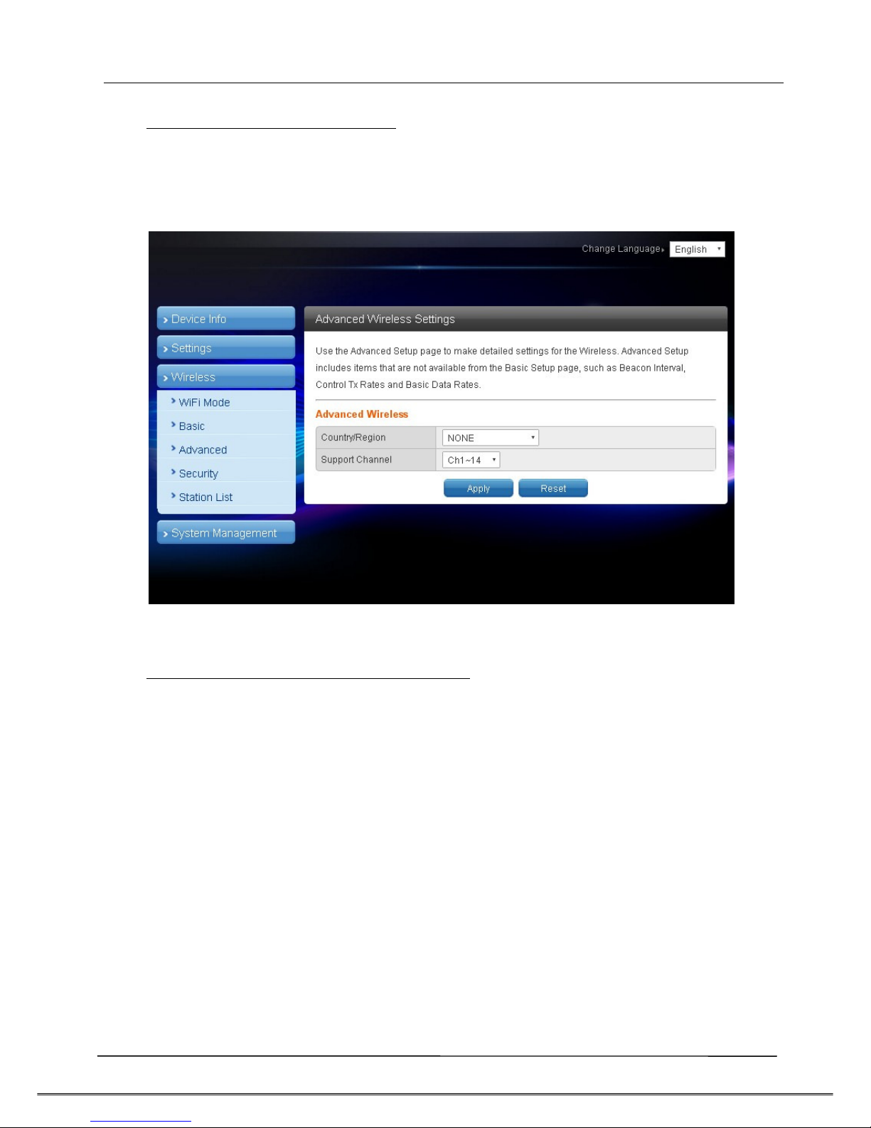
4.1.2 Advanced wireless settings
This option is aimed at setting up country/region and support channel with page
as shown in figure below:
4.1.3 Wireless security/encryption settings
This option is aimed at setting up wireless security and encryption to prevent
e uipment access and monitoring without certification; available security modes
are WPASKWPA2PSK and Disable with factory default set to the latter. See figure
below for page of this option:
Table of contents
Other TECOM Gateway manuals


Popular Gateway manuals by other brands

Verizon
Verizon ASK-NCQ1338 user guide

ZyXEL Communications
ZyXEL Communications P-870HN-51B - V1.0 manual

Amit
Amit BDG761-0P1 Quick installation guide

Cooper
Cooper ProtoNode FPC-N34 Startup guide

Capetti Elettronica
Capetti Elettronica Wine Cap MWDG-ETH Configuration manual

RFI
RFI G-router Quick installation guide


