TECOM AG-300 Plus User manual

AG-300 Plus
Gateway
User
Manual
Copyright ©
2018,
All
Rights Reserved.
Ver:
R02 D/C:
106-1123

AG-300 Plus Gateway User
Manual
Federal Communication Commission Interference Statement
This
equipment
has
been
tested and
found
to
comply with the
limits
for
a Class B
digital
device,
pursuant
to
Part 15
of
the FCC Rules.
These
limits
are
designed
to
provide
reasonable
protection
against
harmful interference in a residential
installation.
This
equipment generates,
uses
and
can
radiate radio
frequency
energy
and,
if
not
installed
and
used
in accordance
with
the
instructions,
may
cause
harmful
interference
to
radio communications.
However,
there is no
guarantee
that
interference
will
not occur in a
particular
installation.
If this equipment
does
cause
harmful
interference
to
radio or
television
reception,
which
can
be determined by turning the equipment
off
and
on,
the
user
is
encouraged
to
try
to
correct
the interference by one or more
of
the following
measures:
Reorient
or
relocate
the
receiving
antenna.
Increase
the
separation
between the
equipment and
receiver.
Connect the
equipment
into an outlet on a
circuit
different
from that to which the receiver is
connected.
Consult the
dealer
or
an
experienced
radio/TV
technician
for
help.
FCC Caution: Any
changes
or modifications
not
expressly approved by the
party
responsible
for
compliance
could
void the user's
authority
to
operate this equipment.
This
device
complies
with Part 15
of
the FCC Rules.
Operation
is subject
to
the
following
two
conditions:
(1)
This
device
may
not
cause
harmful interference,
and
(2)
this
device must accept
any
interference
received,
including
interference
that
may
cause
undesired operation.
CE
Declaration
of
Conformity
This
equipment
complies
with
the requirements relating
to
electromagnetic compatibility,
EN55032
class B
for
ITE
and EN
50082-1.
This
meets
the essential protection requirements
of
the European
Council
Directive
89/336/EEC
on the approximation of the
laws
of
the Member
States
relating
to
electromagnetic
compatibility.
Environment
The
device
you
have
purchased,
as well as any
used
batteries must not be
disposed
of
with
household waste. You
should
return these
to
your
distributor
if
they
are
to
replaced
or dispose
of
them
in an
approved
recycling
center.
Trademarks
iPad™, iPad mini™, iPhone™,
iTunes
™ and
iOS
™
are
registered trademarks
of
Apple Inc., USA.
Android is a trademark
of
Google
Inc., or others are registered trademarks
of
their
respective
owners.
WARNING!
1. Read
these
installation
instructions
carefully
before connecting the device
to
its
power.
2.
To
reduce
the
risk
of
electric
shock, do not
remove
the cover
from
the
device
or
attempt
to
dismantle
it. Opening
or
removing
covers
may
expose
you
to
dangerous
voltage
levels.
Equally,
incorrect reassembly
could
cause
electric
shock on
re-use
of
the
appliance.
3. Do
not
expose
the device
to
Fire,
direct
sunlight
or
excessive
heat.
4. Do not expose the device
to
rain
or
moisture
and
do not allow it
to
come
into contact
with
water.
5. Do
not
install
the
device in an
environment
likely
to
present a
THREAT
OF
IMPACT.
6. You
may
clean the device using a
fine
damp
cloth.
Never
use
solvents
(such
as
trichloroethylene or acetone),
which
may
damage
the device
’s plastic surface.
Never
spray
the device
with
any
cleaning product
whatsoever.
7.
The
device is
designed
to
work
in temperatures
from
-40
C
to
80
C.
Page
2
o o

AG-300 Plus Gateway User
Manual
8.
The
device
must
be
installed
at least 1 meter from radio frequency equipment,
such
as TVs,
radios, hi-fi
or
video
equipment
(which radiate
electromagnetic
fields).
9. Do not attempt
to
upgrade
device in an
unstable
power
environment.
This
could cause
unexpected
issues.
10.
Do
not
work
on
the
system
or
connect or
disconnect
cables
during
lightning
storms.
11.
Children do
not
recognize the
risks
of
electrical appliances.
Therefore
use
or
keep
the device
only
under supervision
of
adults
or
out
of
the
reach
from
children.
12.
No repair
can
be
performed
by the end user,
if
you
experience trouble with this equipment,
for
repair
or
warranty
information,
please
contact
your
supplier.
Page
3

AG-300 Plus Gateway User
Manual
Contents
Introduction
......................................................................................................................................
5
Setting
up
the
Gateway
.......................................................................................
.............................
6
1. Wiring
the
Devices
..........................................................................................................
.6
2. RS-485
wiring method
...................................................................................................
..
7
3.
PM-300
PT/CT
wiring
method
.....................................................................................
…9
4.
Dimensions
of
devices..................................................................................................
….10
5.
AG-300
Plus
Views
.........................................................................................................
..10
6.
PM-300
Views
...................................................................................................................
11
7. TT-300
Views
....................................................................................................................
12
8. VB-200ST/VB-200SC
Views
........................................................................................
...13
9. Vibration
gauge
installation
position
(recommended)
......................................
..........13
10.
Installation
Precautions
...............................................................................................
...15
11.
Installation
Reference
...................................................................................................
...16
Device
Settings
...............................................................................................................................
..19
1.
Network
Settings
...........................................................................................................
..19
2. Account
Settings
............................................................................................................
...20
3.
Electromechanical
equipment
configuration
................................................................
22
4. TT-300
Settings
..............................................................................................................
..24
5. VB200
Settings
.................................................................................................................
26
6. ElecMeter
(PM-300)
Settings
.....................................................................................
....30
7.
Wireless
setup
..................................................................................................................
33
7.1
The
wireless AP
mode
configuration
(WiFi
mode
setup)
.........................
....
..33
7.2
WiFi mode
setting
................................................................................................
..38
8.
Hardware
Settings
.........................................................................................................
..42
The
setting
instructions
of
Teco
inverter
and
Tecom
AG-300
Plus
Gateway
................
...........44
The
App
Software
Operation
.....................................................................................................
...46
Page
4
AG-300 Plus Gateway User
Manual
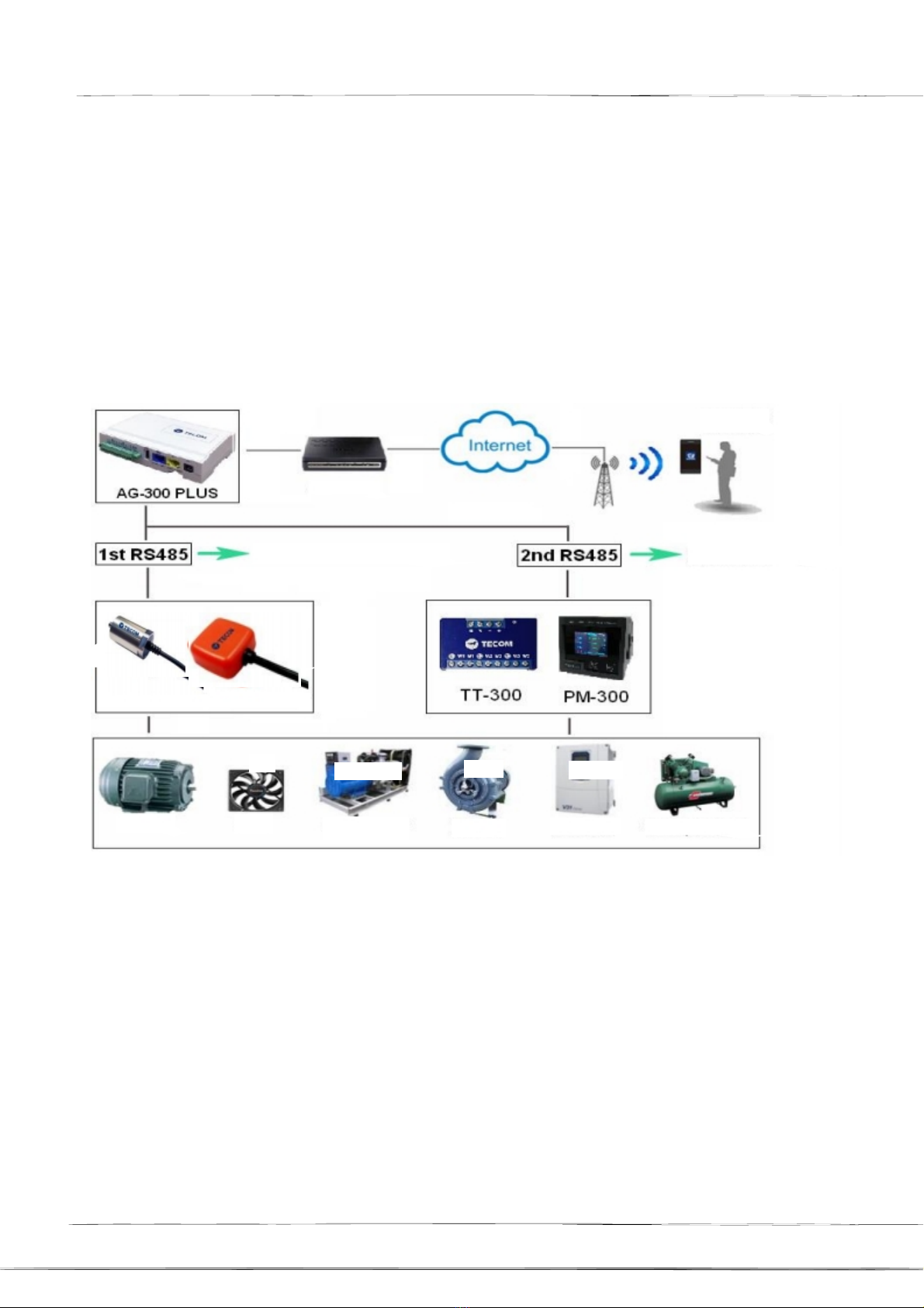
Introduction
The
Gateway
AG-300
Plus,
Temperture
Transducer TT-300, Accelerometer VB-200 and Multi-
function
Power
Meter
PM-300
and so on. It is
suitable
for measuring the
temperature,
vibration and
many
power
data
in the
power
panel,
electromechanical,
rotational
mechanical
market.
Gateway
can
benifit
you
easy
to
manage
your
manufacture
electromechanical
devices,
make
sure
your
equipment
is
in
a healthy
state
and
prevent
catastrophic
downtime.
ADSL
Modem
Baud
Rate
=
115200
Vibration
Gauge
Baud
Rate
=
9600
VB-200SC
振
動
規
VB-200ST
振動
規
Motor
Fan
Generator
Pump
Inverter
Compressor
變
頻
器
.
Page
5
AG-300 Plus Gateway User
Manual
Setting
up
the
Gateway
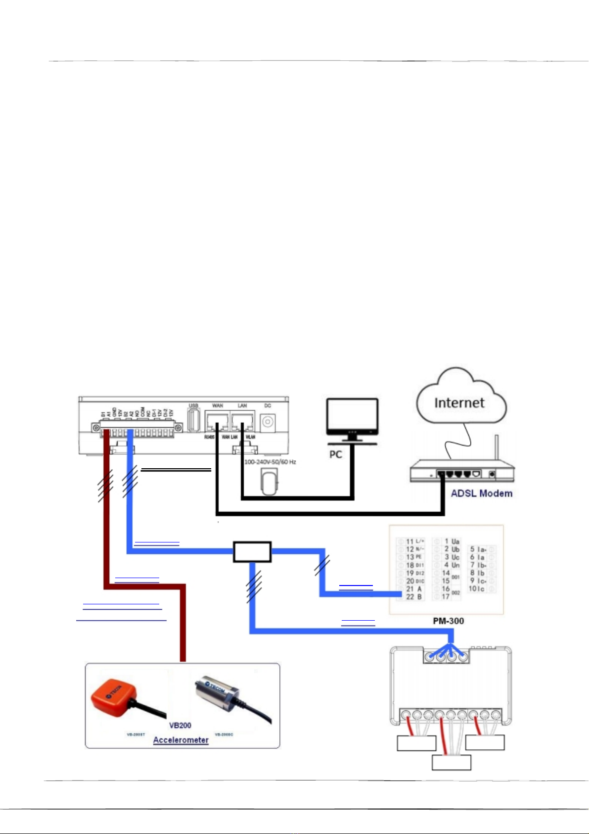
1.
Wiring
the
Devices
After
unpacking
the
product
package
box,
please
connect the
devices
by
following
the connection
figure as shown in below figure.
A. The
AG-300
Plus WAN
port
(blue)
connects
to
the
ADSL
modem
LAN
port
via the
network
cable.
B. The
AG-300
Plus is
connected
to
the
TT-300
and VB-200 or
three-phase
meters
(PM-300)
via
RS-485.
C.
AG-300
Plus
LAN
port
(yellow)
Connect
to
PC via
network
cable.
(For
setup only)
B
RS485
A
C
AG-300 Plus
C
A
RS-485#2
TB
RS-485#1
B
RS-485
VB200 requires a
B-2-1
RS-485
RS485
B-1
RS485
B-2-2
RS485
TT-300
TS200
TS200
TS200
Page
6
2.
AG-300 Plus Gateway User
Manual
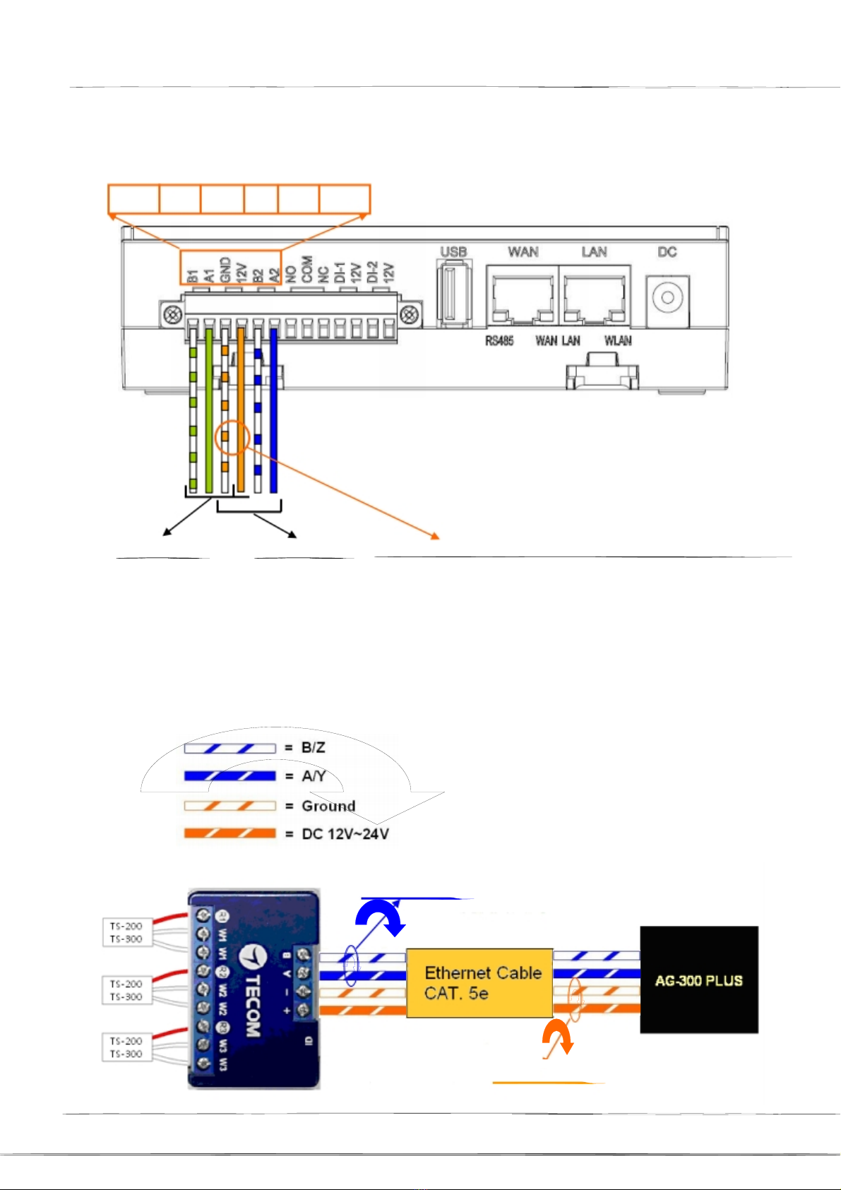
RS-485
wiring
method
(1)
AG-300
Plus
B/Z1
A/Y1
GND
12V
B/Z2
A/Y2
1’st RS485
(2)
TT-300
2’nd RS485
GND
and
12V
are
common
used
by
both
RS485s
A. Connect
TT-300
to
AG-300 Plus by
using
CAT5e
(or
CAT6)
cable.
B.
Total
two
twisted
pairs
of
CAT5e cable are used;
one
twisted
pair
for RS485
signal,
and
the
other
twist pair
would
be used
for
power
and
ground.
(RS485-)
(RS485+)
Twisted
Pair
Twisted
Pair
Page
7
AG-300 Plus Gateway User
Manual
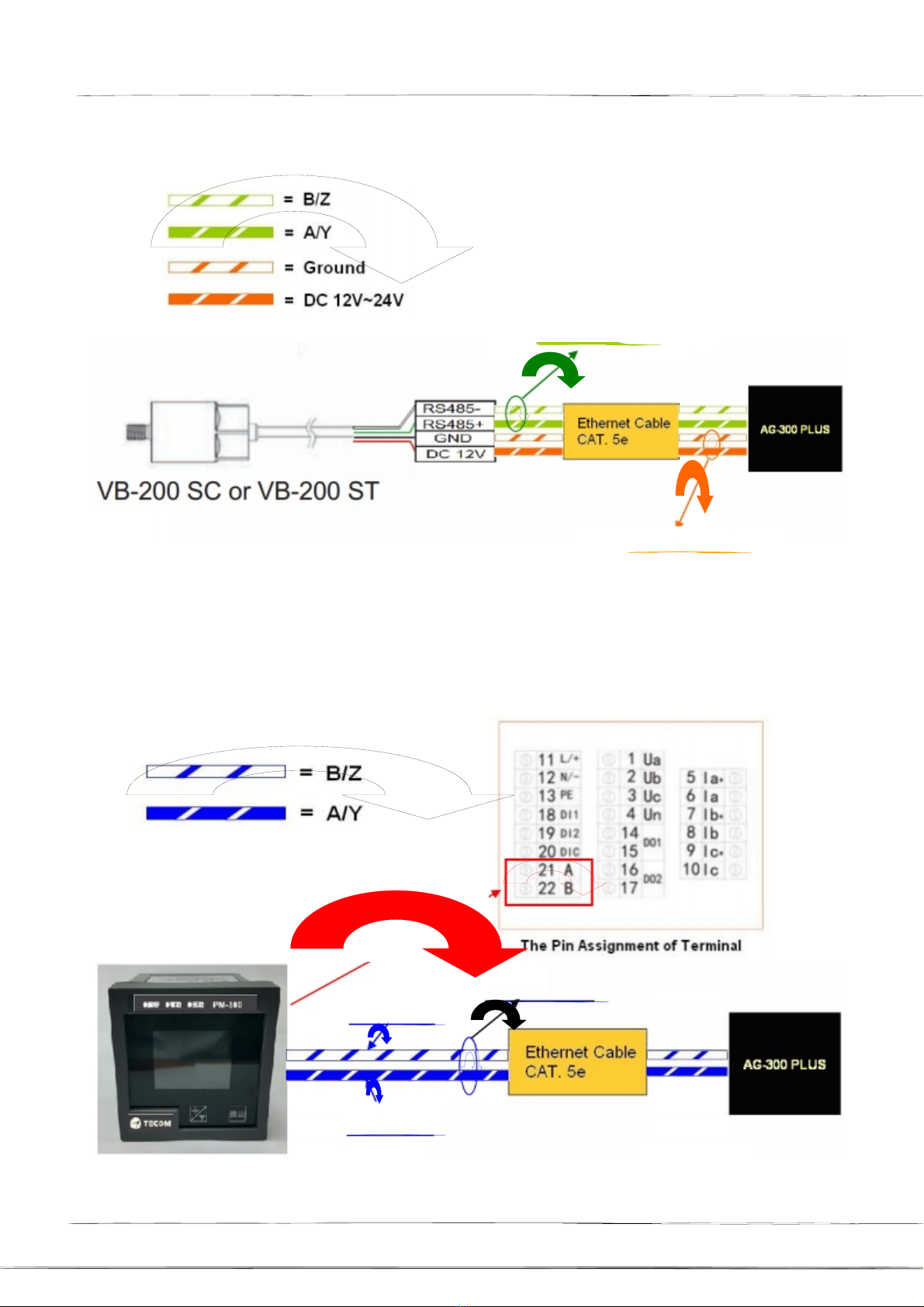
(3)
VB-200ST/VB-200SC
(RS485-)
(RS485+)
Twisted
Pair
Twisted
Pair
(4)
PM-300
(RS485-)
(RS485+)
Pin
22
(B)
Pin
21
(A)
Twisted
Pair
Page
8

3.
AG-300 Plus Gateway User
Manual
PM-300
PT/CT
wiring
method
Attention
and
warnings
(1) It is
prohibited
to
carry
out
wiring
work
during
power
is on line.
(2)
After
the
input
power
cut
OFF,
do not touch the
circuit
or change the wiring
before
the status P
LED
of
PM-300
went
off.
(3) The Ia/lb/lc &
la*/lb*/lc*
input
terminals
for
current
measurement
and
Ua/Ub/Uc/Un
input
terminals
for
voltage
measurement
MUST NOT be inter-
connected.
(4) Please refer
to
the following
wiring
connection for
integrating
CT and PT
together.
(5)
After
the
completion
of
wiring, Power ON can only be
conducted
after
the
confirmation
together
with
the
on-site
electricians.
Page
9

AG-300 Plus Gateway User
Manual
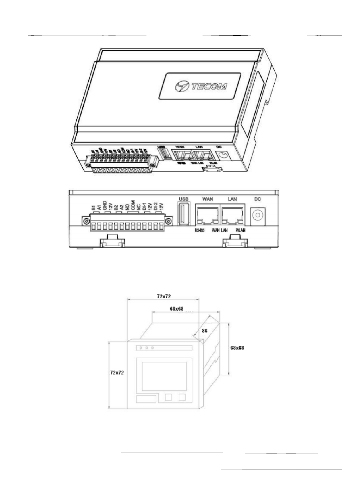
4.
Dimensions
of
devices
(1)
AG-300
Plus
dimensions
: 130mm
(L)
x
99mm
(W)
x 36 mm (H) (2)
PM-300 dimension : 72mm (L) x
72mm(W)
x 86mm
(H)
(3)
TT-300
dimension : 59mm (L) x
36mm(W)
x 16mm (H)
(4) VB-200ST dimensions :
30.5mm
(L) x 30.5mm
(W)
x
11.5mm
(H) (5)
VB-
200SC dimensions : Ø23.5 * 38.0 mm
5.
AG-300
Plus
Views
Page
10
AG-300 Plus Gateway User
Manual
6.
PM-300
Views
Page
11

AG-300 Plus Gateway User
Manual
7.
TT-300
Views
Page
12
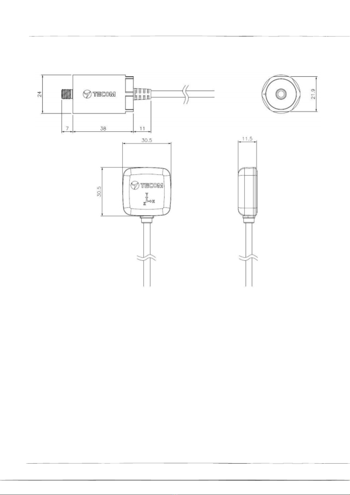
8.
AG-300 Plus Gateway User
Manual
VB-200ST/VB-200SC
Views
9.
Vibration
gauge
installation
position
(recommended)
Vibration
measurement
must
observe
the following rules
according
to
ISO-10816
standard.
1.
Close
to the
bearing
2. In direction
either
vertical or horizontal rather than
45-degrees
or
tilted
direction
3.
See
diagram
below
for
recommended
installation
position
where
the
arrow
symbol
indicates
direction
and letter "x"
the
installation
position.
Page
13

.
.
AG-300 Plus Gateway User
Manual
Vertical
Vertical
Axial
Vertical
Horizontal
Axial
Vertical
Horizontal
Axial
Horizontal
Horizontal
Axial
3 Axials X/Y/Z
Position
Vibration
gauge
3-axis
direction
3 Axials
X/Y/Z
Installation
Location
安
裝位
置
圖
Direction
identificat
ion
VB-200ST
Direction
identification
on the Logo
Recognition
in the
direction of the bulge line
VB-200SC

AG-300 Plus Gateway User
Manual
10.
Installation
Precautions
(1) VB-200SC is only
suitable
for
installation
with
screw
holes.
If you want to
add
magnet,
please
use
VB-200ST
instead.
(2) VB-200ST original magnet on the surface of the flatness
requirements,
can not
be
used in the
cylindrical
motor. It
must
use a two-legged magnet on
VB-200ST,
please call your
representative
for
this application.
(3) VB-200ST
double-sided
adhesive
thickness
is 0.6
mm,
so paste the surface smooth
enough
to
flat, convex part
must
less
than
0.3 mm, slightly smaller pits do not
affect.
(4) The vibration
gauge
wire
must
be
loosened.
The
wire
close to the vibration gauge
body
can
not be
tightened.
Therefore,
pay
attention
when
handling
the wire, and
leave
some
flexibility
to allow the
wire
to move
freely
without affecting
the
vibration.
(5) After vibration
gauge
installation
is completed, you can
shake
the
vibration gauge by hand,
the
vibration
gauge
must
be
very
solid, no
shaking
phenomenon,
otherwise
the
vibration value
will
increase,
but
also
increases
the
frequency
of
unpredictable.
In
practice,
the
vibrating
gauge
mounted
with
a magnet
will
be
secured
with
a
quick-drying
glue.
(6) The point of
installation
must
be thick
steel,
such
as a motor
body.
Do
not install on fan
covers
or heat sink fins or thin iron
plates
because they are too thin and
easy
to
resonate,
vibration
values increase, and
produce
unexpected
frequencies.
(7) Generally, the
vibration
value
will
be less than 10 mm / s. If
the
vibration of the motor
itself is not
large
and
the
vibration
value is large,
please
re-check
if the
installation
point
and the
vibration
gauge
are
installed
securely.
(8) This vibration frequency response frequency range is
1-1130Hz,
the
speed
of 200Hz and
below
(inclusive) of the
motor
is
very
applicable, because
we
can
observe
five times the
frequency. If the rotation
speed
of the
rotating
machine
exceeds
500Hz, only double
the
frequency can be
observed.
This
vibration mode is not applicable. If the
rotation
speed
of
the
rotating
machine
is
lower
than 10Hz, the low frequency
part
must
be specially treated,
please
use
the
low frequency
vibration gauge
instead.
Page
15

AG-300 Plus Gateway User
Manual
11.
Installation
Reference
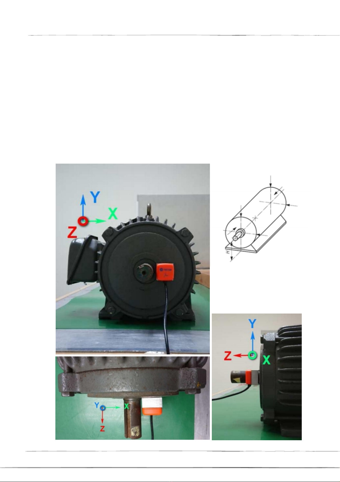
11-1
Vertical
When the
vibration
gauge
is
installed
in the vertical direction, it
should
be placed
just
above
the
rotating
shaft. At this time,
the
Z-axis of the vibration gauge is the vertical direction.
Please
note that the
two
legs
of
the
magnet are parallel to the rotating
shaft
so that they can
be fixed on
the
arc
surface
of the motor on.
Z
Y
X
Z
Y
X
X
Z
X
Y
X
X
Z
X
Y
X
When using
the
vertical installation
position, the figure
represents
the
measured correct X,
Y,
Z
vibration
axis.
Page
16
AG-300 Plus Gateway User
Manual
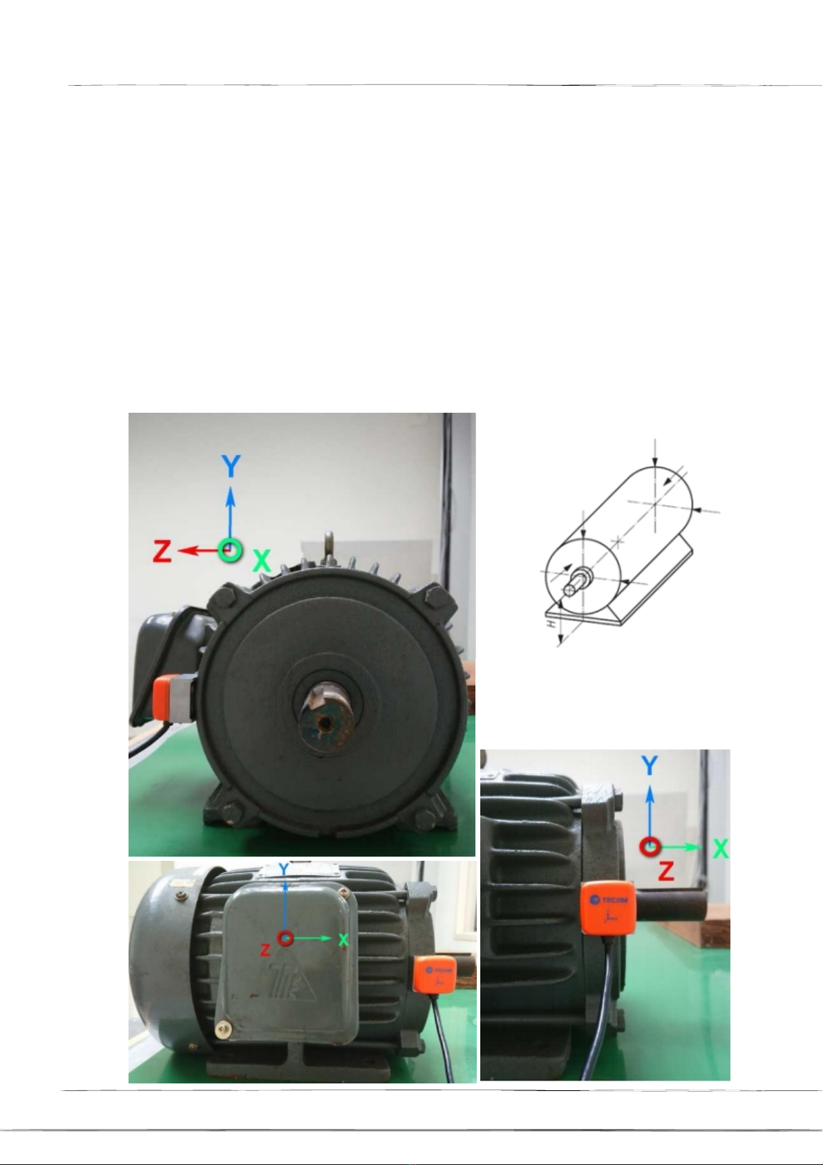
11-2
Horizontal
When the vibration gauge is
installed
in the horizontal direction, it
should
be placed on
the level of the
rotation
axis,
does
not put too
high,
so as not to
increase
the vibration
value. Put the higher position, the
greater
the value of the horizontal vibration. At this
time, the Z axis of the vibration gauge is the horizontal direction.
If
you
measure
only
one
point,
it
is recommended to
use
this point. Vibration
measurement
of the vertical direction,
to be placed on top of the rotating shaft, then
the
vibration of the Z-axis is the vertical
direction, please
note
that the
two
legs of
the
magnet parallel to the axis of rotation, it can
be fixed in the motor arc on.
Y
X
Y
X
X
Z
X
Z
X
X
Z
X
Z
X
When
using
a
horizontal
mounting
position,
the
figure
represents
the
correct
measured
axial
direction
of
vibration.
Page
17
AG-300 Plus Gateway User
Manual
11-3
Axial
When the vibration gauge measurement value is the
axial
direction, it
must
be
placed on
the
level of the
rotation
axis, do not put too high, so
as
not to
increase
the vibration value.
Put the higher position, the
greater
the
value of the horizontal vibration. At this
time, the Z axis of the vibration gauge is the horizontal direction.
If
you
measure
only
one
point,
it
is recommended to
use
this point. Vibration
measurement
of the vertical direction,
to be placed on top of the rotating shaft, then
the
vibration of the Z-axis is the vertical
direction, please
note
that the
two
legs of
the
magnet parallel to the axis of rotation, it can
be fixed in the motor arc on.
Y
X
Y
X
Z
X
X
Z
X
X
When using
the
axial
installation
position, the figure
represents
the
measured correct
vibration
axis.
Page 18
18
AG-300 Plus Gateway User
Manual
Device
Settings
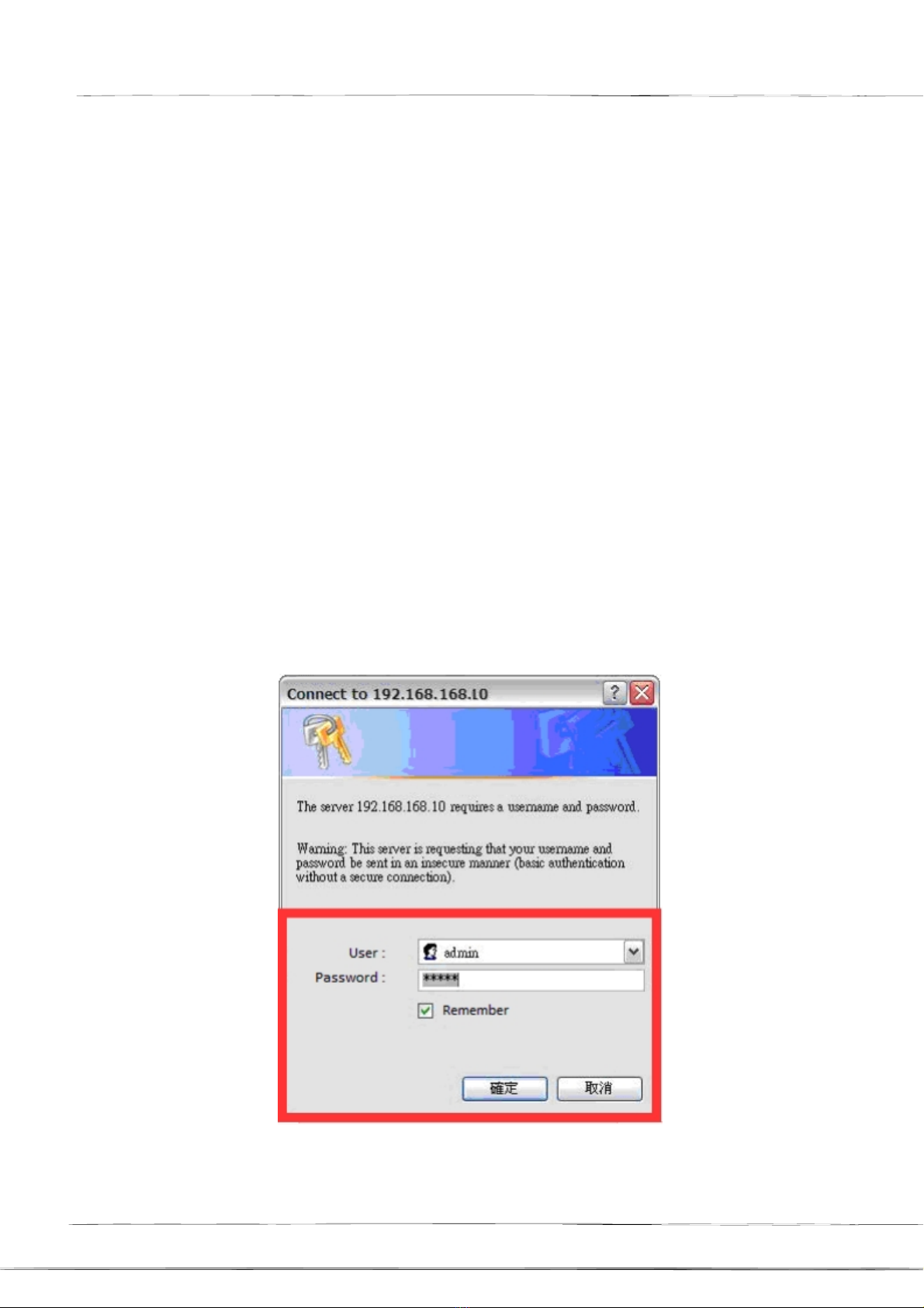
1.
Network Settings
Step
1
- Make
sure
your
PC/NB
and
the
AG-300
Plus
e-Gateway
are
in the
same
LAN
(Recommended
to
use
DHCP
on
your
PC/NB)
- Connect an Ethernet
cable
point-to-point
between
Notebook/PC
and
AG-300
Plus
(LAN
Port)
- Connect the
power
adapter
to
AG-300
Plus
- The
computer
opens
the
browser,
and
the
address
bar
enters
the
AG-300
Plus setup
page
URL
http://192.168.168.10
-
Enter
the user
name:
admin
-
Password:
IP585xAdmin,
- Click
OK.
Page
19
AG-300 Plus Gateway User
Manual
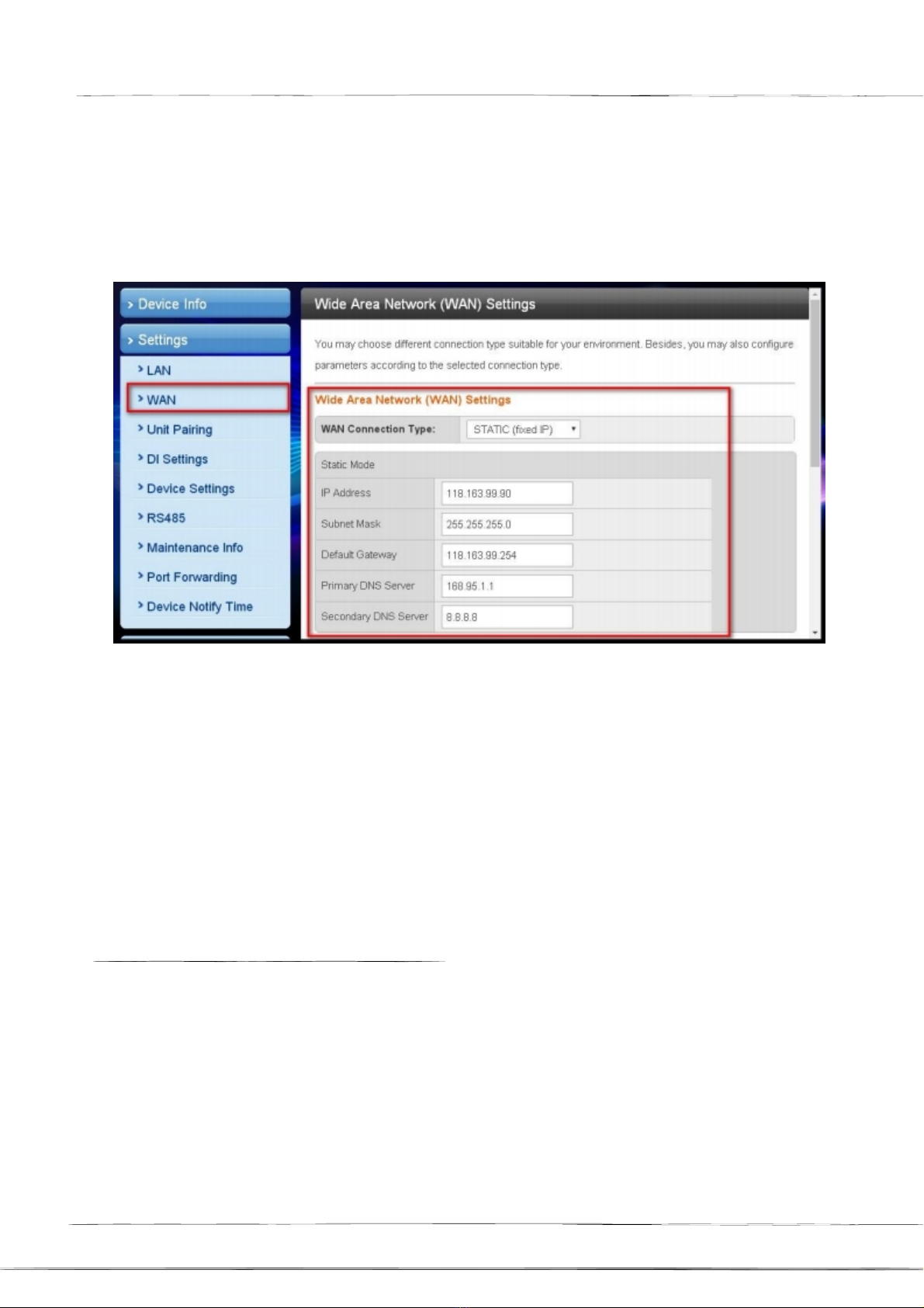
Step
2
(if
the
network
is
DHCP plug
and
play,
you
can
omit
this
step)
- In the left
main
menu click
to
use the
【Settings
】【
WAN
Settings
】.
- Please select【
STATIC
(fixed
IP)
】
in the
WAN
Connection
Type
Pull-down
menu.
- IP
Address:
Please
enter
the
IP
address
information.
- Subnet
mask:
Please
enter
subnet
mask
information.
-
Default
Gateway:
Please
enter
the
preset
gateway
information.
-
Primary
DNS
Server:
Primary
DNS
Server
Information.
-
Secondary
DNS server: Secondary DNS
server
information.
- Please click
the
【
Apply
】
button
at the
bottom
of
the
page.
After
the
WAN
Settings
is
completed,
please
use
the
browser
to
try
to
open
the
edition.cnn.com,
www.yahoo.com.tw and
other
pages,
if
the
smooth
opening means
that
the
external
network
function
is
normal.
If
have
firewall
management,
Please
use
the
mobile
phone
APP
communication
port
by
TCP
53100
~
53199.
2.
Account
Settings
Step
1
Page
20
Table of contents
Other TECOM Gateway manuals


Popular Gateway manuals by other brands


ZyXEL Communications
ZyXEL Communications Unified Security Gateway ZyWALL 300 user guide

IXXAT
IXXAT CME/PN Hardware manual

RTA
RTA 460QT-NNA4 Product user guide

ICP DAS USA
ICP DAS USA GT-541 user manual

HMS
HMS Intesis INBACHIT O000 Series Installation sheet

Technicolor
Technicolor TG789vac v2 installation guide