TECSYSTEM T538 User manual


http://www.tecsystem.it
T538
Software rel. 3.1
INSTRUCTION MANUAL
TECSYSTEM S.r.l.
Via Cristoforo Colombo, 5/C
20094 Corsico (MI)
tel. +39 - 02 - 48601011 / 4581861
Fax: +39 - 02 – 48600783
T538 protection relays
TECSYSTEM S.r.l ®
R.6 17/09/03
T538
Software rel. 3.1

3
T538 protection relays
TECSYSTEM S.r.l ®
1) TECHNICAL SPECIFICATIONS
AUXILIARY POWER SUPPLY
Rated voltage 24-240 Vac-dc
Maximum ratings 20.270 Vac-dc
Vdc with reversible polarities
COMMUNICATION
Opt. Output RS232/485 Modbus® RTU
INPUTS
8 inputs RTD Pt100 sensors-3 wires
removable rear terminals
input channels protected against elec-
tromagnetic noises and spikes
sensors length cables compensation
up to 500 m (1mm²)
opt. 8 analog inputs 4-20 mA (range 0-
240°C)
OUTPUTS
2 alarm relays (ALARM-TRIP)
1 alarm relay for sensor fault or working
anomaly (FAULT)
output contacts capacity: 5A-250Vac
res.
Arranged for output relays test
ALARM & TRIP programming for Fail
Safe and NO Fail safe
Opt. Relay AUX.1 (FAN)
TESTS AND PERFORMANCES
Assembling in accordance with CE
rules
Protection against electrical and mag-
netic noises: CEI-EN50081-2/50082-2
Dielectric strength 2500 Vac for 1 min.
from relays to sensors, relays to power
supply, power supply to sensors
Accuracy: ± 1% full scale, ± 1 digit
Ambient operating temperature –20°C
to +60°C
Humidity 90% no-condensing
ABS self-extinguishing housing
NORYL 94VO
Burden 3VA
Data storage 10 years minimum
Digital linearity of sensors signal
Self-diagnostic circuit
Opt. Protection treatment of electronic
part
Opt frontal plastic protection
DISPLAYING AND DATA MANAGEMENT
1display 13mm high 3 digit with 3 digit
for displaying temperatures
8 LED for displaying reference channel
8 LED indicating alarm or trip
LED indicating fault
Temperature monitoring from 0°C to
240°C
2 alarm thresholds for each input
sensors diagnostic (Fcc-Foc-Fcd)
entering the programming by frontal
push button
automatic output from programming cy-
cle after 1 min. of no-operation
wrong programming automatic display
programmed data call out
possibility of setting manual channel
scanning or hottest channel
maximum temperatures storage
number of channels software program-
DIMENSIONS
96x96mm-DIN43700-Prof.150mm
(with rear terminals)
panel cutout 92x92mm
Rated voltage 24-240 Vac-dc
Rated voltage 24-240 Vac-dc
. Output RS232/485 Modbus® RTU
OUTPUTS
2 alarm relays (ALARM-TRIP)
2 alarm relays (ALARM-TRIP)
1 alarm relay for sensor fault or working
1 alarm relay for sensor fault or working
anomaly (FAULT)
anomaly (FAULT)
output contacts capacity: 5A-250Vac
output contacts capacity: 5A-250Vac
res.
Arranged for output relays test
Arranged for output relays test
ALARM & TRIP programming for Fail
ALARM & TRIP programming for Fail
Safe and NO Fail safe
opt. 8 analog inputs 4-20 mA (range 0-
opt. 8 analog inputs 4-20 mA (range 0-
240°C)
LED indicating fault
Temperature monitoring from 0°C to
Temperature monitoring from 0°C to
240°C
96x96mm-DIN43700-Prof.150mm
2 alarm thresholds for each input

4T538 protection relays
TECSYSTEM S.r.l ®
2) MOUNTING
Make a hole with the dimensions of 92x92 mm in the panel plate.
Fasten firmly the unit by the fixing blocks you are equipped with.
3) POWER SUPPLY
The T538 unit has an Universal Power Supply: it can be supplied indifferently from 24 to
240 Vac-dc without any respect of the polarities.
This particularity is obtained by the application of a tried power supplier which provides the
installer free from the worries concerning the correct Vac or Vdc power supply.
The ground cable must be fixed to the clamp 41.
When the unit is supplied directly from the secondary of the transformers to protect, it can
be fulminated by high intensity overvoltage.
This happens when the charge is connected with the locking of the master switch.
This is much more evident when the 220 Vac voltage is obtained directly from the bars of
the secondary of the transformers and there is a fixed phase adjustment condenser of the
same transformer.
In order to protect the electronic apparatus, we suggest the application of the elec-
tronic discharges of the serie PT73 –220 which have been studied by Tecsystem Srl
for this specific purpose.
Alternately, we suggest the application of a power supply by 24 Vac or better 24 Vdc.
4) ALARMS ELECTRICAL CONNECTIONS
Carry out the electrical connections on the removable terminal board after having taken
them off from the apparatus (follow the Fig.1).
ALARM and TRIP relays energize only when the prefixed temperature limits are reached
(NO Fail Safe) or deenergize when the prefixed temperature limits are reached (Fail Safe).
The FAULT relay energizes always when the apparatus is powered and it de-energizes
when the Pt100 are damaged or when there is not any power supply voltage.
2) MOUNTING
The T538 unit has an Universal Power Supply: it can be supplied indifferently from 24 to
The T538 unit has an Universal Power Supply: it can be supplied indifferently from 24 to
240 Vac-dc without any respect of the polarities.
Make a hole with the dimensions of 92x92 mm in the panel plate.
Make a hole with the dimensions of 92x92 mm in the panel plate.
Fasten firmly the unit by the fixing blocks you are equipped with.
3) POWER SUPPLY

5
T538 protection relays
TECSYSTEM S.r.l ®
5) MEASURE SIGNALS TRANSPORT
All the transport cables of the Pt100 measure signals must absolutely:
be divided from the power ones
be realized with shielded cable with twisted conductors
have a section of min 0,5 mm²
be twisted if you have not any shield
be firmly fixed in the terminal board
have tinned or silvered conductors
All the serie “T” units have the sensors linearization with a max error of 0,5% v.f.s..
TECSYSTEM srl has realized a special cable for the measure signal transport with
all the protection requirements in accordance with CEI Normes: mod. CT-ES
6) WARRANTY
The serie “T” units are under warranty for 12 months from the delivery date signed on
the unit.
The warranty is recognised when the unit breaks down due to some production faults or
insufficient calibration.
The warranty is not valid when the unit is tampered with or when it has been damaged
for a wrong sensors connection or wrong power supply, out of the max working limits
(20÷270 Vac-dc). The warranty is not valid when the unit has been fulminated by exces-
sive transitory voltages. In this case TECSYSTEM Srl does not answer for damages
caused by faulted or defective units. All the delivery expenses (there and back) of the
unit must be paid by the Customer
In case of dispute, the qualified FORUM is the one in Milan.
The warranty is always F.CO our Company in Corsico.
7) PT100 EXTENSION CABLE: TECHNICAL SPECIFICATIONS
Cable 20xAWG 20/19 cu/stg
Section 0,55 mm²
Antiflame Insulation PVC105
In accordance with CEI 20.35 IEC 332.1
Max. working temperature: 105°C
Conformation : 4 terns of numbered conductors (1-1-1.........4-4-4)
RRW twisted and coloured conductors
Cu/stg Shield
PVC Antiflame protecting covering
External diameter 9,0 mm
Skeins of 100 m
All the transport cables of the Pt100 measure signals must absolutely:
5) MEASURE SIGNALS TRANSPORT
7) PT100 EXTENSION CABLE: TECHNICAL SPECIFICATIONS

6T538 protection relays
TECSYSTEM S.r.l ®
8) DISPLAY MODE
Pressing on DISPLAY MODE you establish the visualization ways of the display:
HOT : the unit visualizes automatically the hottest channel
MAN : manual reading of the channels temperature by !
!!
!and "
""
"push-buttons
T.MAX :the unit visualizes the max. temperature reached by the sensors and
the eventual alarms starting from last reset.
SCAN :channels are cyclically every 2 seconds
9) WORKING PROGRAM CONTROL
In order to control the programmed temperature values, you have to push shortly on PRG.
Pushing PRG repeatedly the values established previously appear on the display in se-
quence.
In order to end the visualization you have to push ENT.
10) RANGE
Pressing “SET” button when the unit is on AUTOMATIC working, the ALARM and TRIP
values appear on the display in sequence.
To have a more rapid channels scanning, you have to press many times the SET button.
At the end it is carried out the LAMP TEST
11) LAMP TEST
It is advisable to carry out regularly the LED test of the unit. For this operation you have to
push TEST.
If one of the LED does not work, please send us the unit in order to be repaired.
8) DISPLAY MODE
9) WORKING PROGRAM CONTROL
10) RANGE
11) LAMP TEST
It is advisable to carry out regularly the LED test of the unit. For this operation you have to

7
T538 protection relays
TECSYSTEM S.r.l ®
12) OVER TEMPERATURE ( AUTO and MAN WORKING )
When one or more Pt100 sensors survey higher temperatures than the prefixed ones
switch on:
the GREEN led/s referred to the channel/s
the led referred to ALARM is YELLOW
the led referred to TRIP is RED and the ALARM-TRIP relays commute
When the temperature is 1°C under the prefixed limit, the led switches off and the relay re-
sets.
The over temperature alarm signal is intentionally delayed in order to avoid false alarms
caused by temperature transistors.
The max. temperatures are any way memorized even if their performance time is not
enough long to cause any alarm.
IMPORTANT NOTICE
Before making the insulation test on the electrical panel on which the unit is installed, you
must take it off from the power supply in order to keep it out of damage.
13) FAULT
The T538 monitoring unit is provided with a self-diagnostic program with alarm relay and
visualization of the kind of fault of the sensors.
An additional program allows to distinguish a high temperature signal given by an eventual
defective sensor. In this case the FAULT relays commutes and on the display appears Fcd
with the relative defective sensor.
This particular program avoids the signalization of accidental alarms due to defective sen-
sors which indicate wrong temperature values.
14) DATA STORED DIAGNOSTIC
If the internal memory is corrupted, at the start up on display it appears the message Ech
with the FAULT alarm. In this case the unit uploads the default parameters; press RESET
to delete the FAULT alarm and the Ech message; start a new programming cycle with the
desired parameters.Turn off and turn on the unit to check if memory work properly. If it is
damaged or broken, on display it appears Ech message again. In this case, send the unit
to Tecsystem for reparation.
15) THERMOMETRIC SENSORS DIAGNOSTIC
In the event one of the thermometric sensors installed on the machine to protect is dam-
aged, the FAULT relay energizes immediately, the ALARM and TRIP LED’s of the dam-
aged channel (Chn) lighten and the FAULT LED is lightening.
The screen will automatically display a message showing the fault condition:
· Fcc sensor is short circuited
· Foc sensor is open
· Fcd sensor is fault
12) OVER TEMPERATURE ( AUTO and MAN WORKING )
IMPORTANT NOTICE
13) FAULT
14) DATA STORED DIAGNOSTIC
15) THERMOMETRIC SENSORS DIAGNOSTIC

8T538 protection relays
TECSYSTEM S.r.l ®
16) PROGRAMMING:
LED PROGRAM SWITCH OFF: VISUALIZATION OF THE PROGRAM
LED PROGRAM ON: INPUT TO THE PROGRAM
N° KEY DISPLAY NOTES
1PRG/SET start programming appears nCH
00n Keep pressed the push button PRG/SET for 7”
until stops to lighten to enter the program.
2set up the number n° of the desired
channels from CH1 to CH8
3PRG/SET set T° of ALARM of CH1 appears
4set up the desired limit Set 000 to disable ALARM relay
5PRG/SET Set T° of TRIP of CH1 appears
6set up the desired limit Set 000 to disable TRIP relay
7PRG/SET Repeat same procedure starting
from “2”
8PRG/SET on display Fcd appears
9set up Fcd YES or NO Fcd YES= control of damaged Pt100 con-
nected
10 PRG/SET ONLY IF opt. RS232/RS485
11 set up the Baud rate (E:parity
Even, n:parity None) Baud rate: E1.2 - E2.4 - E9.6 - E19.2
n1.2 - n2.4 - n9.6 - n19.2
12 PRG/SET ONLY IF OPZ. RS485
13 set up address for opt. RS485 from 0 to 32 max
14 PRG/SET on display appears Prg
15 set up Prg YES or no Prg NO= the programming is blocked
16 PRG/SET set up the function of the ALARM
relay
17 function for ALARM Fail Safe YES - Fail Safe NO
18 PRG/SET set up the function of the TRIP relay
19 function for TRIP Fail Safe YES - Fail Safe NO
20 PRG/SET on display appears HLd
21 set up HLd YES or no with HLd YES function HOLD established
22 PRG/SET The message 4.20 appears on
display (only with option 4.20 mA)
23 1-8,HOT Select the channel for 4.20 mA output
24 PRG/SET out of the programming lamp test
25 ENT/
RESET return to step 1
In case exist the option AUX.1 relay, It have to be set the values of FAN OFF and FAN ON, accord-
ing to the programming procedure, starting from point 2.
16) PROGRAMMING:

9
T538 protection relays
TECSYSTEM S.r.l ®
17) HOLD FUNCTION
If you set up by programming HLD-YES, ALARM and TRIP relays will be energized until
the manual reset when the temperatur falls down below the set alarm thresholds. If you do
not want this function you have to establish HLD-NO by !
!!
!and "
""
"push-buttons.
18) PROGRAMMING REHABILITATION IN CASE OF BLOCK (Prg no)
If the programming has been blocked, in order to enter again the programming of the unit,
it is necessary to carry out the following unblocking procedure :
enter the program vision way pushing PRG
keep TEST pushed until PRG stops to lighten. ( LED PROGRAM alight )
During the blocking, pushing PRG for more than two seconds, on the display it appears
“noP” to indicate the impossibility to program the data.
19) ALARM RELAYS TEST
This function allows to test the relays working without any additional instrument.
To carry out the test you have to push TEST for 5 seconds: all the LED will switch on and
on the display will appear tSt lightening.
Release it when the RELAY TEST LED will be alight.
The first relay to test will be indicated by the display and the respective LED will be alight.
The relays to test will be indicated on the display by:
“Fan” : fan relay (if the option is present)
“Flt” : Pt100 fault relay
“Alr” : alarm relay
“TrP” : trip relay
Select the relay to test by !
!!
!and "
""
"push-buttons. Energize it pushing SET and de-
energize it pushing RESET.
In order to stop this procedure, you have to push again TEST and all the relays will be re-
stored to the starting configuration.
After 5 minutes of inactivity of the keyboard, the TEST RELAY procedure will be automati-
cally interrupted.
20) ALARM RELAY EXCLUSION
If you want to exclude the alarm signal, you have to push RESET: the relay de-energizes
and the respective LED, which was alight, starts to lighten. If the transformer temperatures
is still rising, the ALARM relay will energize again until to have a temperature value of 5°C
less than TRIP threshold. In this moment the user can exclude again the ALARM, but in
this case, it will not appear any other indication as regards ALARM relay.
The exclusion system will be automatically disconnected when the temperature falls down
the ALARM threshold.
17) HOLD FUNCTION
18) PROGRAMMING REHABILITATION IN CASE OF BLOCK (Prg no)
19) ALARM RELAYS TEST
20) ALARM RELAY EXCLUSION

10 T538 protection relays
TECSYSTEM S.r.l ®
FAULTS DIAGNOSTIC CAUSES AND REMEDIES
The unit doesn’t switch on even if there is volt-
age to the terminals Connector not well fit in its place.
Connection wires not well closed in the clamp Burnt
power supplier.
Take away and give again voltage.
The sensor is damaged The FAULT relay closes and the FAULT LED
switches on. The RED LED of the relative channel is
lightening. It is indicated on the display the kind of
damage of the sensors:
FOC= sensor open
FCC= sensor in short circuit
One of the eight channels is in FAULT for FOC/
FCC Check the Pt100 sensors connection.
Probable damaged sensor.
Replace the damaged sensor
During the main switch manoeuvre ON-OFF, the
ALARM and TRIP relays energize Strong electrical noises on the power supply line.
Plug in the PT73.
Check if the shield of the signal transport cable is
connected to the ground in the side of the panel.
If you have not any shielded cable, You have to put
it. (Mod. CT-ES).
If it is not at your disposal, twist the three connecting
wires of the sensors.
All the Pt100 sensors are in FCC. Wrong connection of the sensors. Upside-down ter-
minal board.
Check the connections and the terminal board
The temperature indicated by 1 or more chan-
nels is wrong. Pt100 Sensor/s defective.
Check the sensor resistance by an Ohm meter.
Unit with input circuit unrated.
Send the unit to TECSYSTEM S.r.l. for reparation.
With power supply at 24 Vdc, the unit switches
off and , after a tension drop, it doesn’t switch on
again.
Take off the voltage to the unit and check that the
value of the Vdc is from 20 up to 24V.
Give again voltage.
If the unit does not switch on , send the unit back to
TECSYSTEM S.r.l.
Sudden release of the main switch with a normal
temperature level.
An only channel caused the unhooking.
Pt100 sensor defective (Fcd).
Replace the sensor.Check the measure signal ter-
minal board.
FAULTS DIAGNOSTIC
CAUSES AND REMEDIES

11
T538 protection relays
TECSYSTEM S.r.l ®
ELECTRICAL CONNECTIONS
OUTPUT ALARM RELAY WITH FAIL SAFE
60 61 62
RS 232 GND TX RX
RS 485 GND - +
40
41
42 POWER SUPPLY
24-240 VCA-VCC
WHITE
RED
RED
Pt100
13 14 15 19 20 21 25 26 27 31 32 33
CH 1 CH 3 CH 5 CH 7
INPUT Pt100
16 17 18 22 23 24 28 29 30 34 35 36
CH 2 CH 4 CH 6 CH 8
1 2 3
ALARM
4 5 6
TRIP
7 8 9
FAULT
10 11
FAN
1 2 3
ALARM
4 5 6
TRIP
7 8 9
FAULT
10 11
FAN
OUTPUT ALARM RELAY WITH FAIL SAFE ON
70 71 72 73
+ - Vcc Gnd
OUT 4-20 mA
ELECTRICAL CONNECTIONS
41
OUTPUT ALARM RELAY WITH FAIL SAFE
40
60 61 62
RS 232 GND TX RX
RS 485 GND - +
RS 485 GND - +

12 T538 protection relays
TECSYSTEM S.r.l ®
T538 TEST DESCRIPTION
Date of shipment:
N° Description
1 PC board test
2 Input test
3 Test of relay contacts and outputs
4 Key test
5 Lamp test
6 Calibration at 100 and 200°C (Range 0 - 240°C)
7 Software test
8 Burn-in minimum 24h
The unit was submitted to the following tests during production:
T538 TEST DESCRIPTION
This manual suits for next models
3
Table of contents
Other TECSYSTEM Industrial Equipment manuals
Popular Industrial Equipment manuals by other brands
Mayr
Mayr EAS-smartic 484.XX5 Series Installation and operational instructions

Jet
Jet 190918 operating instructions

JMA Wireless
JMA Wireless Weather Protection System WPS-DM-14S installation instructions
Mark 7
Mark 7 APEX 10 user manual
ABB
ABB HT843539 Operation manual
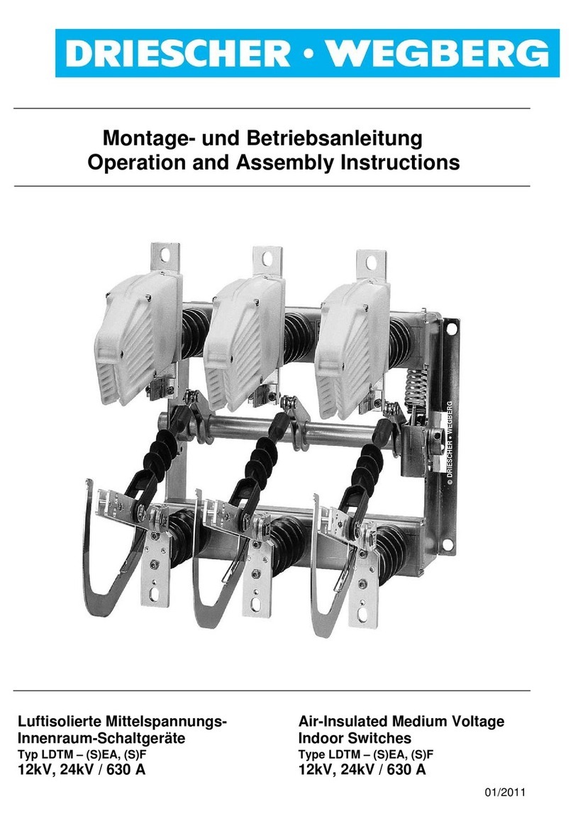
DRIESCHER-WEGBERG
DRIESCHER-WEGBERG LDTM 12/630 F-E EA-E Operation and assembly instructions

