Tecumseh F31HC Installation and user guide

ENGLISH
Installation, Operation, Service
and
Maintenance Instructions
“UNIT COOLERS FOR COLD ROOMS”
Model Series
F31HC / F35HC
UNIT FOR USE WITH WALK-IN COOLER,
FREEZER OR REFRIGERATED WAREHOUSE
2
TABLE OF CONTENTS
INSTALLATION AND OPERATION MANUAL
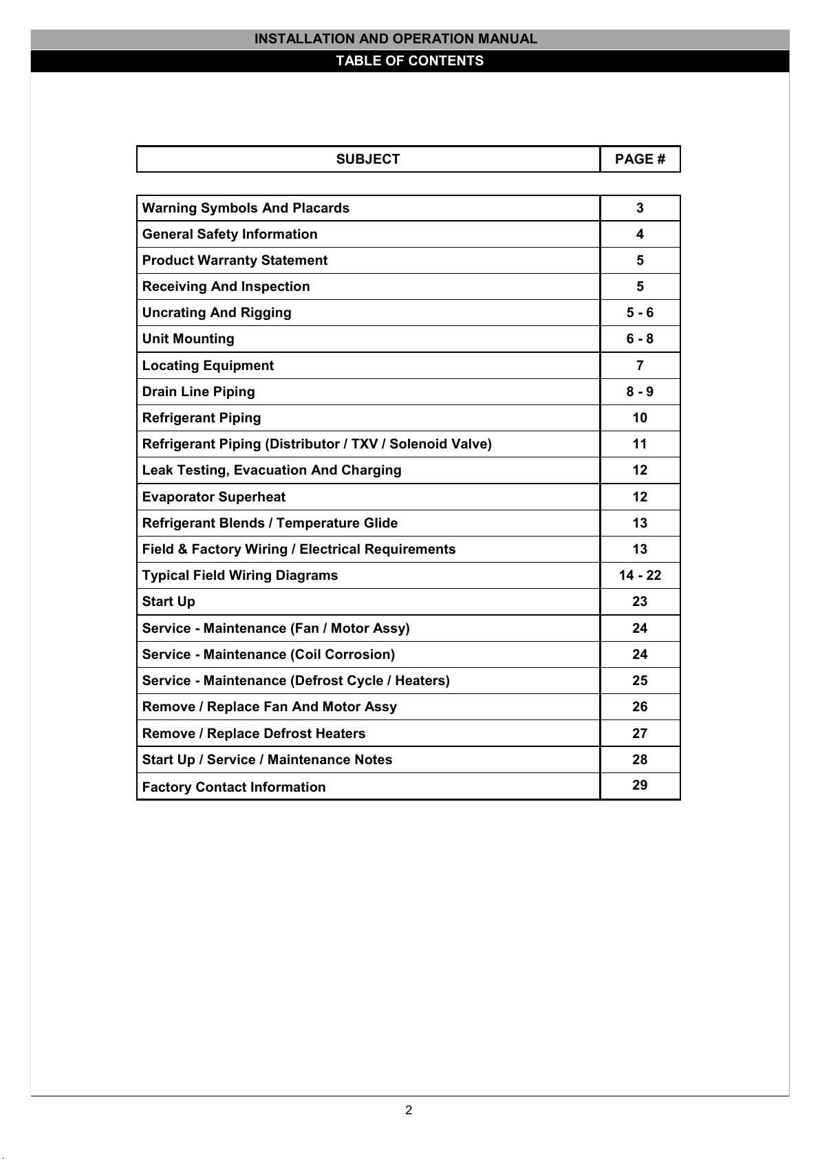
SUBJECT PAGE #
Warning Symbols And Placards 3
General Safety Information 4
Product Warranty Statement 5
Receiving And Inspection 5
Uncrating And Rigging 5-6
Unit Mounting 6-8
Locating Equipment 7
Drain Line Piping 8-9
Refrigerant Piping 10
Refrigerant Piping (Distributor / TXV / Solenoid Valve) 11
Leak Testing, Evacuation And Charging 12
Evaporator Superheat 12
Refrigerant Blends / Temperature Glide 13
Field & Factory Wiring / Electrical Requirements 13
Typical Field Wiring Diagrams 14 - 22
Start Up 23
Service - Maintenance (Fan / Motor Assy) 24
Service - Maintenance (Coil Corrosion) 24
Service - Maintenance (Defrost Cycle / Heaters) 25
Remove / Replace Fan And Motor Assy 26
Remove / Replace Defrost Heaters 27
Start Up / Service / Maintenance Notes 28
Factory Contact Information 29

3
WARNING SYMBOLS AND THEIR MEANING
Check Guard
Ear Protection
Required
Eye Protection
Required
Hand Protection
Required
No Fire, Open
Flame or
Smoking
Sharp ElementOverhead LoadAutomatic StartHot Surfaces
Toxic Substan-
ces
Electricity
Hand Injury Pos-
sible
MANDATORY SIGNS AND THEIR MEANING
OTHER SIGNS AND THEIR MEANING
Protective Clo-
thing Reqd
Forklift Traffic
Connect To Earth
Ground
Use Safety
Footwear
Hard Hat Area
Activate Before
Work
This is only a “Right To Know”
law in the state of CA. It does
not mean that LU-VE products
contain any substance or
materials that may cause cancer
or reproductive harm
4
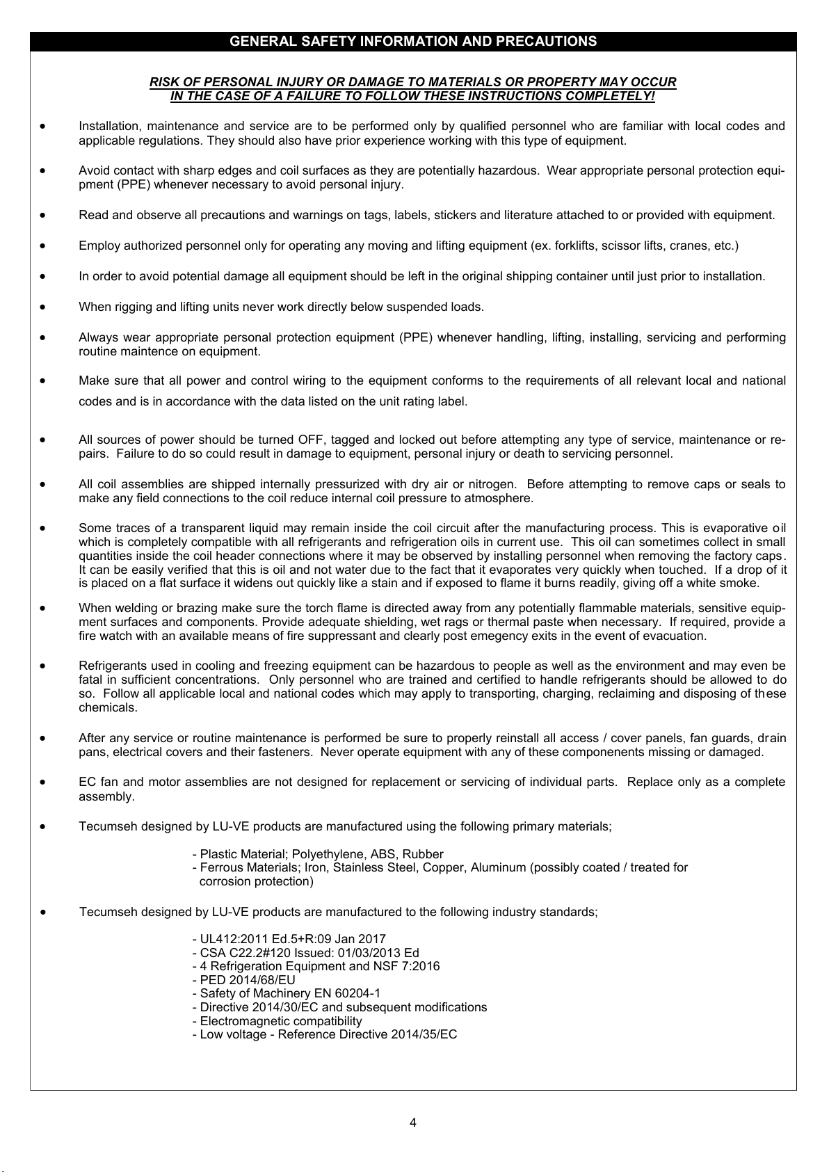
RISK OF PERSONAL INJURY OR DAMAGE TO MATERIALS OR PROPERTY MAY OCCUR
IN THE CASE OF A FAILURE TO FOLLOW THESE INSTRUCTIONS COMPLETELY!
Installation, maintenance and service are to be performed only by qualified personnel who are familiar with local codes and
applicable regulations. They should also have prior experience working with this type of equipment.
Avoid contact with sharp edges and coil surfaces as they are potentially hazardous. Wear appropriate personal protection equi-
pment (PPE) whenever necessary to avoid personal injury.
Read and observe all precautions and warnings on tags, labels, stickers and literature attached to or provided with equipment.
Employ authorized personnel only for operating any moving and lifting equipment (ex. forklifts, scissor lifts, cranes, etc.)
In order to avoid potential damage all equipment should be left in the original shipping container until just prior to installation.
When rigging and lifting units never work directly below suspended loads.
Always wear appropriate personal protection equipment (PPE) whenever handling, lifting, installing, servicing and performing
routine maintence on equipment.
Make sure that all power and control wiring to the equipment conforms to the requirements of all relevant local and national
codes and is in accordance with the data listed on the unit rating label.
All sources of power should be turned OFF, tagged and locked out before attempting any type of service, maintenance or re-
pairs. Failure to do so could result in damage to equipment, personal injury or death to servicing personnel.
All coil assemblies are shipped internally pressurized with dry air or nitrogen. Before attempting to remove caps or seals to
make any field connections to the coil reduce internal coil pressure to atmosphere.
Some traces of a transparent liquid may remain inside the coil circuit after the manufacturing process. This is evaporative oil
which is completely compatible with all refrigerants and refrigeration oils in current use. This oil can sometimes collect in small
quantities inside the coil header connections where it may be observed by installing personnel when removing the factory caps.
It can be easily verified that this is oil and not water due to the fact that it evaporates very quickly when touched. If a drop of it
is placed on a flat surface it widens out quickly like a stain and if exposed to flame it burns readily, giving off a white smoke.
When welding or brazing make sure the torch flame is directed away from any potentially flammable materials, sensitive equip-
ment surfaces and components. Provide adequate shielding, wet rags or thermal paste when necessary. If required, provide a
fire watch with an available means of fire suppressant and clearly post emegency exits in the event of evacuation.
Refrigerants used in cooling and freezing equipment can be hazardous to people as well as the environment and may even be
fatal in sufficient concentrations. Only personnel who are trained and certified to handle refrigerants should be allowed to do
so. Follow all applicable local and national codes which may apply to transporting, charging, reclaiming and disposing of these
chemicals.
After any service or routine maintenance is performed be sure to properly reinstall all access / cover panels, fan guards, drain
pans, electrical covers and their fasteners. Never operate equipment with any of these componenents missing or damaged.
EC fan and motor assemblies are not designed for replacement or servicing of individual parts. Replace only as a complete
assembly.
Tecumseh designed by LU-VE products are manufactured using the following primary materials;
- Plastic Material; Polyethylene, ABS, Rubber
- Ferrous Materials; Iron, Stainless Steel, Copper, Aluminum (possibly coated / treated for
corrosion protection)
Tecumseh designed by LU-VE products are manufactured to the following industry standards;
- UL412:2011 Ed.5+R:09 Jan 2017
- CSA C22.2#120 Issued: 01/03/2013 Ed
- 4 Refrigeration Equipment and NSF 7:2016
- PED 2014/68/EU
- Safety of Machinery EN 60204-1
- Directive 2014/30/EC and subsequent modifications
- Electromagnetic compatibility
- Low voltage - Reference Directive 2014/35/EC
GENERAL SAFETY INFORMATION AND PRECAUTIONS
5
PRODUCT WARRANTY STATEMENT
Subject to the limitations and disclaimers contained herein, Tecumseh Products Company (“Seller”) warrants to its original
equipment manufacturer customer (“OEM”), that any compressors, condensing units, unit coolers, component parts,
controllers, or other goods manufactured by Seller and sold by Seller to OEM (collectively, “Goods”) will be free from defects in
material and workmanship under normal use with regular service and maintenance for the greater of; (a) twenty (20) months from the
date of manufacture by Seller or, (b) eighteen (18) months from the date of invoice (the “Warranty Period”). Products sold by
Seller to Authorized Wholesale (collectively, “Goods”) will be free from defects in material and workmanship under normal use with
regular service and maintenance for a period of sixty (60) months from the date of manufacture by Seller or twelve (12) months
from the date of sale by Tecumseh’s authorized wholesaler, whichever occurs first (the “Warranty Period”).
This WARRANTY does not cover:
•Costs, expenses, or any other type of damage incurred by any other person concerning the repair or replacement of any Goods;
•Any Goods that become inoperative because of system processing, design or installation;
•An indication in the Goods that there is no defect in material or workmanship;
•Transportation costs other than the freight allowance expressly described herein;
•Any Goods where Seller’s serial number, code plate, or serial label is missing, rendered illegible,
tampered with and/or altered in any way; or;
•Goods sold through export unless agreed upon by Seller and Authorized Wholesaler or OEM
in a written service agreement duly executed by the parties authorized representatives.
For more information please contact your local Tecumseh Sales representative or Corporate office at:
Tecumseh Products Company / 5683 Hines Drive / Ann Arbor, MI 48108 / Ph. 734.585.9500 / www.tecumseh.com
RECEIVING AND INSPECTION
When the equipment is initially received, a responsible individual acting on behalf of the equipment purchaser must be present to
check the quantity of cartons and crates being delivered against the bill of lading to confirm that all items listed therein are accounted
for. Inspect all shipping containers (boxes and crates) for any signs of visible damage. Report any damage or shortages to the
delivering freight company immediately. It is the customer's responsibility to file all claims with the freight company. Damaged
equipment may be refused but must not be returned to the manufacturer for any reason without prior authorization.
Installing personnel must exercise caution when removing equipment from crates and boxes to prevent physical injury to themselves
or the product. Always wear appropriate personal protection equipment (PPE) such as hard hats, gloves, safety glasses, safety shoes,
long sleeve shirts and pants, etc. to avoid physical injury. When lifting smaller units by hand always utilize proper lifting techniques to
avoid personal injury. Equipment should be left in the original shipping container whenever possible until just prior to installation. Do
not use piping connections, fan guards, drain pans or other such similar components as lifting points. On larger units which must be
removed from the shipping container or skid with lifting straps make sure to utilize a spreader bar to avoid damage to the units sheet
metal housing.
REMOVING EQUIPMENT FROM SHIPPING CONTAINERS / PACKAGING
If using a forklift roll the unit over onto a wooden pallet with the shipping skid “up” (Figure 1 - Steps 1 & 2 - Page 6).
Remove the banding which holds the cardboard box to the shipping skid, then using a razor knife, carefully cut the box down all (4)
corners and fold the cardboard down onto the pallet, leaving the unit resting on the original cardboard shipping blocks and carton top
flaps (Figure 2 - Step 3 - Page 6).
Remove the (4) nuts and bolts that secure the unit mounting brackets to the shipping skid and lay aside the skid (Figure 2 - Steps 4
& 5 - Page 6).
With the shipping container and skid removed, remove the two side access panels from the ends of the unit and check closely for any
concealed or hidden damage. If any damage is noted, report it to the manufacturer immediately before proceding with the equipment
installation. All units are shipped with approx. 25 PSIG of dry air or nitrogen holding charge in the coil. Use an accurate suction
service gauge to verify internal coil pressure prior to proceeding with the unit installation. Although the absence of pressure or a lower
than nor-mal pressure reading does not necessarily indicate a leak, if the reading is “low” a leak test must be performed before
contrinuing with the installation or requesting a return goods authorization from the distributor or manufacturer (Figure 3 - Step 6 -
Page 6).

6
RIGGING AND MOUNTING
The unit can now be lifted to it’s final mounting position by inserting the
lifting forks into the pallet (Figures 4 & 5 - Step 8) and raising the unit
into place (Figures 4 & 5 - Step 9). On longer units it is important to find
the center “balance point” of the unit and spread the lifting forks wide
enough to avoid tipping.
UNIT MOUNTING POINTS
F31HC
F35HC
16.4
16.4
F31HC
F35HC
16.3
19.2
0.39
0.59 14.8
3/4”MPT
1.33
1.73
5.285.28
F31HC
F35HC
18.7
19.1
Fig. 1
Fig. 2
(0.39
375 (14.8)
F31HC
375 (14.8)
0.39
F35HC 14.8
14.8
2
1
Fig. 3
7
Fig. 4
Fig. 5
9
9
DIMENSIONAL DATA
Check coil pressure with an
accurate service gauge. If
pressure is “low” or “0” the
unit must be checked for
leaks before installation.
(Figure 3 - Step 7).
Do not return the unit to the
distributor or manufacturer
without prior authorization!
UNIT MOUNTING POINTS
Fig. 2
Unit Model Series F31HC 115-4116-4125-4126-4135-4136-4146-4
F31HC 215-6216-6225-6226-6235-6236-6246-6
Number of Fans 12.4” Diam 1 1 2 2 3 3 4
Refrig Conn Liquid ½” ½” ½” ½” ½” ⅝” ⅝”
Refrig Conn Suction ⅝” ¾” ¾” ⅞” ⅞” 1-⅜” 1-⅜”
Dimension A30 30 47-5/8" 47-5/8" 65-3/8" 65-3/8" 83-1/16"
Dimension B19-3/8" 19-3/8" 37-1/8" 37-1/8" 54-13/16" 54-13/16" 72-1/2"
Unit Model Series F35HC 73-4106-4145-4215-4272-4323-4362-4430-4
F35HC 59-684-6117-6174-6218-6261-6290-6348-6
Number of Fans 13.8” Diam 1 1 2 2 3 3 4 4
Refrig Conn Liquid ½” ½” ½” ⅝” ⅝” ⅝” ⅝” ⅞”
Refrig Conn Suction 1-⅛” 1-⅛” 1-⅛” 1-⅛” 1-⅜” 1-⅜” 1-⅝” 1-⅝”
Dimension A34" 34" 56" 56" 77-3/4" 77-3/4" 99-5/8" 99-5/8"
Dimension B23-1/2" 23-1/2" 45-3/8" 45-3/8" 67-3/16" 67-3/16" 89-1/16" 89-1/16"
Dimension C--- --- --- --- --- --- 44-1/2" 44-1/2"
7
RECOMMENDED UNIT COOLER PLACEMENT
Air flow within the refrigerated space is critical to achieving optimum cooling and freezing results. If air flow is compromised
for any reason the unit may not provide satisfactory cooling performance. There are many potential reasons for poor air
flow - few of which are the result of inadequate system capacity or unit malfunction. Some of the more obvious reasons for
poor airflow include;
- Unit installed above doors (coil blocked with frost / ice)
- Insufficient return air space between unit and wall
- Insufficient free area in front of the unit
- Unit mounted to close to beams or product racking
- Multiple units installed to close together
- Low ceiling height / unit mounted to close to floor level
- Units mounted perpendicular / blowing at right angles to each other
- Poor product packaging or improper product stacking arrangement
- Too much product loaded into the room at one time
- Wrong unit design for application
- Too few units for room volume
- Multiple, miss-matched units or fan types used in the same room
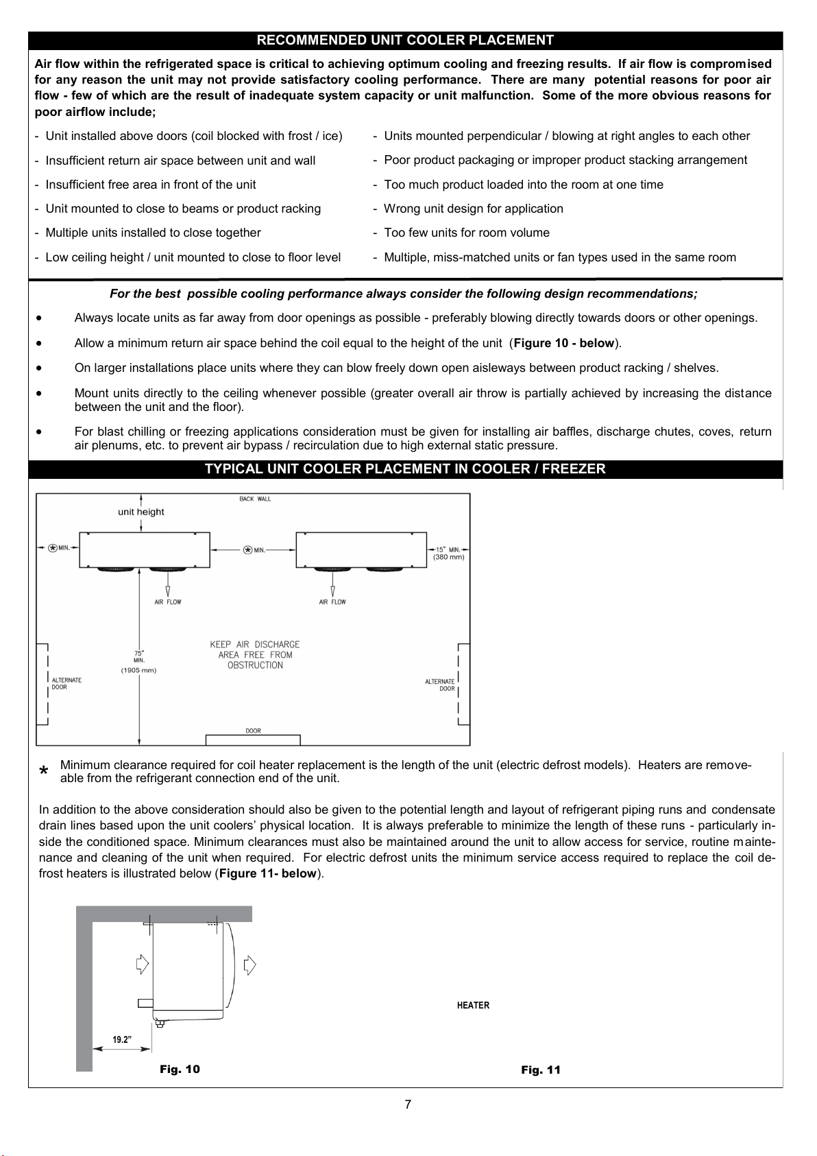
For the best possible cooling performance always consider the following design recommendations;
Always locate units as far away from door openings as possible - preferably blowing directly towards doors or other openings.
Allow a minimum return air space behind the coil equal to the height of the unit (Figure 10 - below).
On larger installations place units where they can blow freely down open aisleways between product racking / shelves.
Mount units directly to the ceiling whenever possible (greater overall air throw is partially achieved by increasing the distance
between the unit and the floor).
For blast chilling or freezing applications consideration must be given for installing air baffles, discharge chutes, coves, return
air plenums, etc. to prevent air bypass / recirculation due to high external static pressure.
TYPICAL UNIT COOLER PLACEMENT IN COOLER / FREEZER
Minimum clearance required for coil heater replacement is the length of the unit (electric defrost models). Heaters are remove-
able from the refrigerant connection end of the unit.
In addition to the above consideration should also be given to the potential length and layout of refrigerant piping runs and condensate
drain lines based upon the unit coolers’ physical location. It is always preferable to minimize the length of these runs - particularly in-
side the conditioned space. Minimum clearances must also be maintained around the unit to allow access for service, routine mainte-
nance and cleaning of the unit when required. For electric defrost units the minimum service access required to replace the coil de-
frost heaters is illustrated below (Figure 11- below).
19.2”
Fig. 10
HEATER
Fig. 11
*

8
UNIT MOUNTING DETAIL
Units should be mounted flush to a level ceiling panel using 3/8” stainless steel bolts, hangar rods or lag screws.
There is no need to block or pitch the unit to ensure proper condensate drainage if the unit is mounted level.
NSF SANITATION
Seal the gap between the top of the unit and the ceiling with NSF approved sealant to prevent accumulation of dirt and foreign material.
CONDENSATE DRAIN PAN CONNECTION
Apply an approved pipe thread sealant to the threads of the drain pan
fitting before making the field piping connection.
Do not torque / over-tighten the field pipe fitting attached directly to the
drain pan connection! Use a backer wrench on the drain pan fitting and tighten
the attached pipe fitting no more than approx. 1/2 turn beyond hand tight.

9
CONDENSATE DRAIN LINES
CONDENSATE DRAIN LINE PIPING — SINGLE UNIT
It is the installers responsibility to ensure that all drain line piping is installed in accordance with local and national plumbing
codes.
Drain line piping runs should be kept as short as possible within the conditioned space whenever possible.
Pitch all field piping in the direction of flow a minimum of 1/4” per foot of pipe run.
Use an approved pipe thread sealant on the threads of the drain line fitting. DO NOT OVER-TIGHTEN THE FITTING
ATTACHED DIRECTLY TO THE DRAIN PAN CONNECTION!
Install a P-trap in all unit drain lines. Traps in freezer drain lines should be located outside the freezer whenever possible.
The use of plastic (PVC) pipe is acceptable only on cooler applications operating above freezing.
For all freezer applications (+32 degrees and lower) use copper pipe only.
Use an insertion type drain line heater on all freezer applications or wrap all piping and P-traps exposed to freezing temperatures
with self regulating type heat tape and insulate wherever practical. A minimum of 20 watts / foot of drain line is generally recom-
mended for freezers operating down to 0 degrees and 30 watts / foot of drain line for those operating from 0 down to -20 de-
grees.
Common drain lines serving multiple units (whether in the same space or different rooms) must be adequately sized to handle the
condensate flow from ALL connected evaporators. DO NOT REDUCE THE DRAIN LINE PIPE SIZE SMALLER THAN THE
CONNECTION ON THE DRAIN PAN! The branch lines from each individual evaporator must also be separately trapped.
All drain lines must terminate above an open floor drain or in an outdoor area where the condensate will not pose any personal
safety or environmental issues. Do not connect drain lines directly to the building sewer system.
Check the unit drain pan after an initial period of operation to ensure there is no standing water in the pan. Check unit for level or
correct field piping if necessary to eliminate standing water.
CONDENSATE DRAIN LINE PIPING — MULTIPLE UNITS ON A COMMON DRAIN LINE
P-Trap
Open Floor Drain
UNI T1UNI T2
P-Trap
UNI T3
Pitch In Direction Of Flow - 1/4" / Foot (MINIMUM))
P-Trap
Air Flow
P-Trap
Floor
COOLER (Above +32)
Open
Drain
FREEZER (Below +32)
Air Flow
P-Trap
Floor
COOLER (Above +32)
Drain
Open
Units which are located in different rooms but piped to a com-
mon drain line must be individually trapped.
Units operating near or below freezing should be trapped out-
side the room or adequately protected from freezing.
10
REFRIGERANT PIPING
CAUTION! UNIT IS PRESSURIZED
WITH DRY AIR OR INERT GAS
FOR SHIPPING
THIS HOLDING CHARGE MUST
BE VENTED AND THE SYSTEM
LEAK TESTED AND EVACUATED
BEFORE CHARGING WITH RE-
FRIGERANT
CHARGE SYSTEM WITH ONLY
PURE, VIRGIN REFRIGERANT
Use only clean, sealed ACR grade copper tubing for refrigerant duty. Unit warranty cover-
age may be voided if system is installed with any other type of tubing. All piping must be
installed according to local and national codes as well as accepted commercial refrigeration
industry standards and practices. All tubing should be cut using a wheel type tubing cutter
(no hacksaws) and all cut tubing must be de-burred. Clean all joints with sand cloth and
apply a small amount of high quality paste flux (being careful to avoid placing any flux near
the ends of the tubing) before firmly joining connections. When brazing, use only high tem-
perature, silver bearing solder on all joints while continuously flowing a regulated, low pres-
sure, inert gas through the inside of the piping to avoid the formation of scale and copper
oxides.
Note: The line sizing required for the system is not necessarily the same size as the factory
pipe connections supplied on the unit. We strongly recommend that you work directly with
an experienced consulting engineer to properly size and design system piping however as a
convenience to our customers (and with no liability for services provided as gratis) we can
supply the installer with line sizing charts which may be used to select the field line sizing
based upon the calculated, overall equivalent feet of tubing (lineal feet plus allowances for
fittings), refrigerant type, unit capacity and SST.
Refer to ASHRAE REFRIGERATION HANDBOOK for detailed system piping design information!
Always consider the overall length of field piping runs when locating unit coolers and matching condensing units. Excessively
long piping runs should be avoided whenever possible.
Select the optimum pipe size which minimizes total system pressure drop while maintaining sufficient internal gas velocities to
ensure continuous oil return back to the compressor. Often times pipe selection is a compromise between operating efficiency
over the lifetime of the system and initial, installed cost.
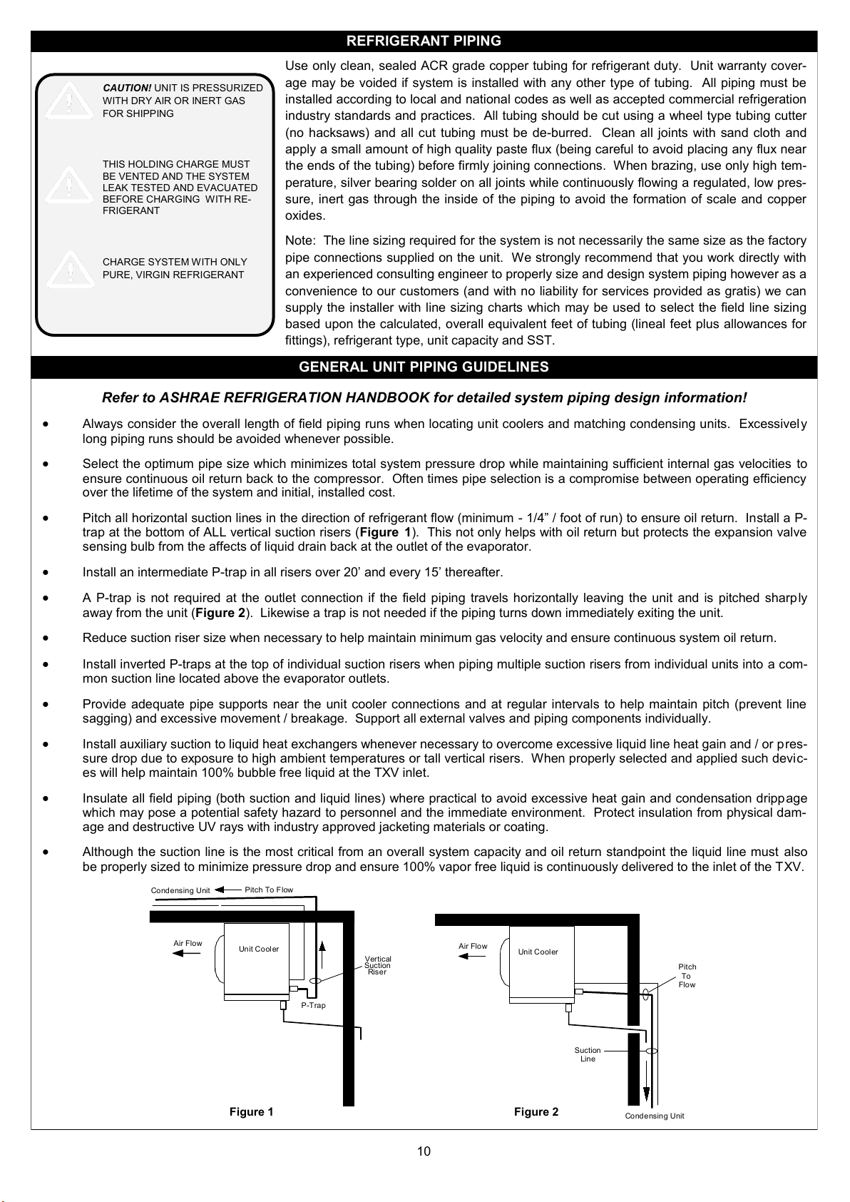
Pitch all horizontal suction lines in the direction of refrigerant flow (minimum - 1/4” / foot of run) to ensure oil return. Install a P-
trap at the bottom of ALL vertical suction risers (Figure 1). This not only helps with oil return but protects the expansion valve
sensing bulb from the affects of liquid drain back at the outlet of the evaporator.
Install an intermediate P-trap in all risers over 20’ and every 15’ thereafter.
A P-trap is not required at the outlet connection if the field piping travels horizontally leaving the unit and is pitched sharply
away from the unit (Figure 2). Likewise a trap is not needed if the piping turns down immediately exiting the unit.
Reduce suction riser size when necessary to help maintain minimum gas velocity and ensure continuous system oil return.
Install inverted P-traps at the top of individual suction risers when piping multiple suction risers from individual units into a com-
mon suction line located above the evaporator outlets.
Provide adequate pipe supports near the unit cooler connections and at regular intervals to help maintain pitch (prevent line
sagging) and excessive movement / breakage. Support all external valves and piping components individually.
Install auxiliary suction to liquid heat exchangers whenever necessary to overcome excessive liquid line heat gain and / or pres-
sure drop due to exposure to high ambient temperatures or tall vertical risers. When properly selected and applied such devic-
es will help maintain 100% bubble free liquid at the TXV inlet.
Insulate all field piping (both suction and liquid lines) where practical to avoid excessive heat gain and condensation drippage
which may pose a potential safety hazard to personnel and the immediate environment. Protect insulation from physical dam-
age and destructive UV rays with industry approved jacketing materials or coating.
Although the suction line is the most critical from an overall system capacity and oil return standpoint the liquid line must also
be properly sized to minimize pressure drop and ensure 100% vapor free liquid is continuously delivered to the inlet of the TXV.
GENERAL UNIT PIPING GUIDELINES
Condensing Unit
Pitch
Suction
Line
Air Flow Unit Cooler
Pitch To Flow
To
Flow
Suction
P-Trap
Air Flow
Vertical
Riser
Condensing Unit
Unit Cooler
Figure 2Figure 1
11
REFRIGERANT PIPING — CONTINUED
All F31HC and F35HC model series unit coolers are equipped with a venturi-flo refrigerant distributor
which ensures maximum efficiency of the coil under most all operating conditions. There is no orifice
or nozzle plate to select / install in the distributor inlet. For optimum coil performance the TXV should
be mounted within the end compartment of the unit and as short a distance as possible from the dis-
tributor inlet. Do not install any elbows between the outlet of the TXV and the inlet of the distributor!
A 1/4” O.D. equalizer tube is supplied on all units. Never cap this line - use only externally equalized
valves. See Figures 4, 5 & 6 (below) for location and mounting of the TXV sensing bulb.
If not supplied with the unit, the expansion valve must be selected according to the design characteris-
tics of the particular system - taking into consideration the following criteria; Refrigerant type, design
room temperature, system TD or design saturated suction temperature (SST), liquid temperature
(subcooling) and the minimum operating head pressure (SCT) of the system. LU-VE can provide a
separate valve selection table of suggested expansion valves for the most common refrigerants, oper-
ating temperatures and system TD’s however we strongly recommend that you consult with your sup-
plier or valve manufacturer for selection assistance - especially for any unusual or non-standard appli-
cations.
If a liquid line solenoid valve is to be installed in the system we recommend placing it in the field piping reasonably close to the unit
cooler. Do not select valves based only on the physical connection size - the valve you install may be much to large for the application
which can result in operational problems with the valve and possibly even damage to the connected unit cooler or system piping. Re-
fer to the valve manufacturers capacity charts or selection software or consult with your local valve supplier for assistance. Always be
sure to provide adequate pipe clamps and supports for external piping and components - never allow the unit coil connections to sup-
port the weight or unrestricted movement of any field installed piping components. Any damage to the coil which is determined to be
caused by improper field piping design / installation will void the product warranty coverage.
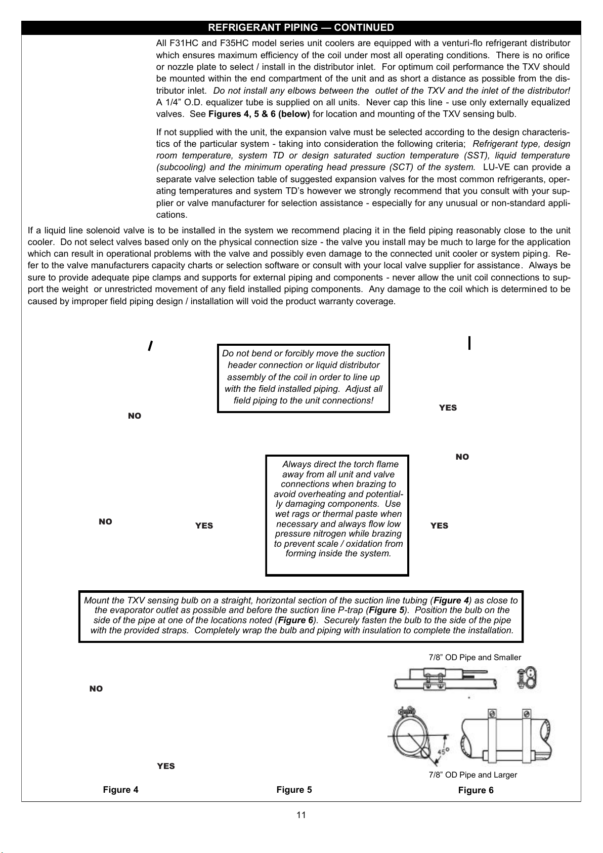
Do not bend or forcibly move the suction
header connection or liquid distributor
assembly of the coil in order to line up
with the field installed piping. Adjust all
field piping to the unit connections!
NO
YES
NO YES
Always direct the torch flame
away from all unit and valve
connections when brazing to
avoid overheating and potential-
ly damaging components. Use
wet rags or thermal paste when
necessary and always flow low
pressure nitrogen while brazing
to prevent scale / oxidation from
forming inside the system.
NO
YES
Mount the TXV sensing bulb on a straight, horizontal section of the suction line tubing (Figure 4) as close to
the evaporator outlet as possible and before the suction line P-trap (Figure 5). Position the bulb on the
side of the pipe at one of the locations noted (Figure 6). Securely fasten the bulb to the side of the pipe
with the provided straps. Completely wrap the bulb and piping with insulation to complete the installation.
Figure 5
NO
YES
Figure 6
Figure 4
7/8” OD Pipe and Smaller
7/8” OD Pipe and Larger
12
LEAK TESTING
Once all field piping connections have been made and the braze joints visually inspected for any obvious voids or gaps introduce a
trace amount of the system refrigerant through a service gauge manifold to achieve an equalized, static pressure of 25 to 30 PSIG.
Make sure that all service and shut off valves are in the open position and slowly introduce a regulated, inert gas such as nitrogen to
increase the static system pressure to approx. 150 PSIG.
Note: Always verify the MAXIMUM system test pressure allowed for all other components in the system before pressurizing
to this level!
Allow sufficient time for the entire sealed system to achieve an equalized test pressure before physically checking all braze joints and
installed system components (both field and factory) with an electronic leak detector. Be sure to turn off the fans of any units operating
nearby or block all air movement with tarps or baffles during testing. If any leaks are indicated double check the suspected area using
soap bubbles, a strong light and an inspection mirror (if necessary). Note the location of any leaks found, reduce the system pressure
to atmosphere, repair the leak(s) (being sure to again flow low pressure nitrogen inside the system while brazing), then repeat the pre-
viously used test procedure to confirm all leaks have been satisfactorily repaired. Allow the system to stand at test pressure overnight
if possible (or several hours at a minimum), and confirm that there has been no discernable pressure decay during that time.
EVACUATION AND CHARGING
All refrigeration systems must be properly evacuated prior to charging with refrigerant. Simply purging the system with refrigerant or
skipping this important step entirely will result in system operational problems, shortened equipment life and voiding the product war-
ranty coverage. Use a deep vacuum pump which has been properly maintained and the oil recently changed. Connect the pump
(along with an electronic micron gauge) using a service gauge manifold with large bore hoses or tubing. Operate the vacuum pump
continuously during the entire evacuation process (larger volume systems may take several hours and multiple pump oil changes to
achieve a satisfactory vacuum level). Monitor the micron gauge during this time and when a minimum reading of 400 microns is
achieved, blank off the gauge, shut off the pump and observe the gauge for 10-15 minutes. At this point, if the system is tight and dry,
there should be no observed decay of the vacuum gauge reading. Break the vacuum with the correct system refrigerant and charge
as per the system design requirements.
Note: Always refer to the manufacturers charging data for the system condensing unit as the unit cooler operating charge
represents only a very small portion of the total, year round operating charge required for the entire system. Be sure
to charge any refrigerant blend as a liquid (not vapor) in order to avoid fractionization.
EVAPORATOR SUPERHEAT
In order to maximize evaporator efficiency and total system capacity a superheat reading must be taken at all system evaporators and
the expansion valve(s) adjusted when necessary to optimize coil performance. Pressures and temperatures should be monitored dur-
ing the initial room pulldown, final readings taken and valve adjustments made (if required) once the room is at or near the design op-
erating temperature and ideally, before the product has been loaded. For most applications with normal traffic patterns, stable operat-
ing room temps and uniform frost loading on the coil (SST below +32 degrees) the optimum, operating superheat at the evaporator
outlet should be in the range of 6-10 degrees. If valve control is extremely stable then lower is typically better to ensure maximum coil
performance. If box traffic and product loading is excessive, coils are located near areas of high moisture infiltration (not recommend-
ed) then a slightly higher operating superheat is recommended in order to protect the system compressor from possible valve over-
feeding. Most compressor manufacturers recommend a minimum of 20 degrees superheat at or near the compressor inlet and on
very close coupled systems some compromise may need to be made to protect the compressor. The use of a suction to liquid heat
exchanger or suction accumulator may be necessary in applications where minimum compressor superheat cannot be maintained.
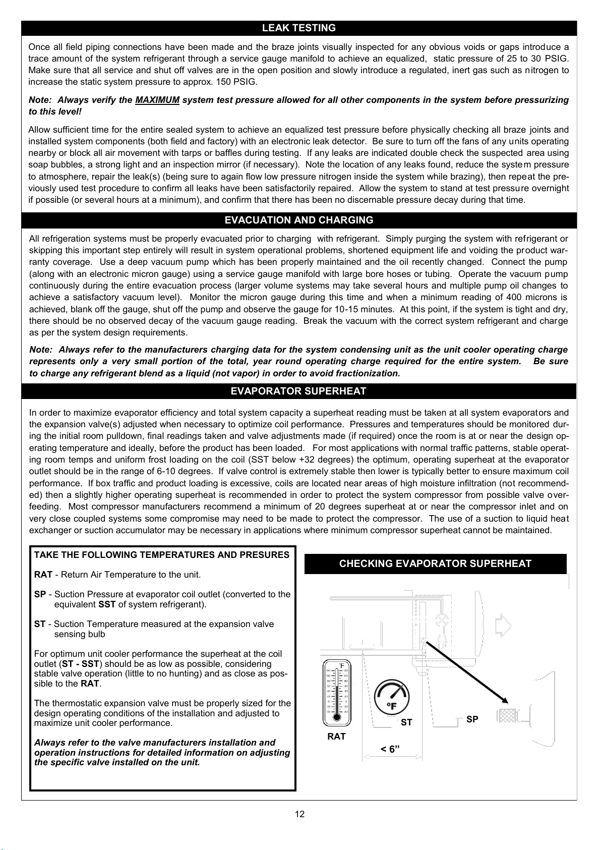
TAKE THE FOLLOWING TEMPERATURES AND PRESURES
RAT - Return Air Temperature to the unit.
SP - Suction Pressure at evaporator coil outlet (converted to the
equivalent SST of system refrigerant).
ST - Suction Temperature measured at the expansion valve
sensing bulb
For optimum unit cooler performance the superheat at the coil
outlet (ST - SST) should be as low as possible, considering
stable valve operation (little to no hunting) and as close as pos-
sible to the RAT.
The thermostatic expansion valve must be properly sized for the
design operating conditions of the installation and adjusted to
maximize unit cooler performance.
Always refer to the valve manufacturers installation and
operation instructions for detailed information on adjusting
the specific valve installed on the unit.
CHECKING EVAPORATOR SUPERHEAT
SP
ST
RAT
< 6”

13
REFRIGERANT BLENDS — TEMPERATURE GLIDE
The majority of HFC refrigerants in use today are referred to as refrigerant “blends” (composed of two or more different refrigerants).
As such, each component within this “blend” evaporates (or condenses) at different temperatures. The temperature range within which
each of these different refrigerants completely changes state from a liquid to a gas (or vice versa) is referred to as “temperature glide”.
Essentially this means that the traditional way we measure superheat and liquid sub-cooling must be adjusted to account for this tem-
perature “glide”. Depending upon which one of these refrigerant is used in the system the temperature glide could range from as low
as 6 to perhaps as high as 12 degrees. Technically R-404A is also a blend but since it’s temperature glide is only around 1 degree it is
typically treated as an azeotrope (a refrigerant whose components boil and evaporate at the same temperature).
When measuring superheat at the evaporator outlet of a system utilzing any of these high glide rfrigerants you must always refer to the
refrigerants’ “Dew Point” which is the point at which the last droplet of liquid refrigerant has vaporized. These values are all listed for
easy reference on all current temperature pressure charts, mechanical and electronic service gauge manifolds and apps commonly
used by todays field service technicians. If in doubt about the values you’ve measured always refer to published data supplied by the
various refrigerant manufacturers to confirm your field measurements. Regardless of which type of refrigerant is used in the system
the service technicians goal is still the same - to maximize the evaporator performance while ensuring both adequate compressor motor
cooling and the prevention of liquid floodback.
The diagram on the right graphically illustrates the relationship
or “glide” of two different components making up a single refrig-
erant blend as they pass through the evaporator coil. The
number on the left of the / mark represents the percentage of
refrigerant “A” and the number to the right of the / mark repre-
sents the percentage of refrigerant “B” which is present at each
location (1, 2 & 3) in the evaporator coil.
Note that the mixture is only equal (50/50) at the inlet
(100% liquid) and at the outlet (100% vapor) of the evapo-
rator coil.
FIELD WIRING — ELECTRICAL REQUIREMENTS
The electrical characteristics of each unit are clearly marked on the unit rating label located on the front facing, left hand end cover of
the unit (as viewed facing the fans). This label lists the operating voltage, phase and amp draw of the fan motors and defrost heaters
(when equipped). It also lists the MINIMUM CIRCUIT AMPACITY (MCA) and MAXIMUM OVER CURRENT PROTECTION DEVICE
(MOPD) which should be used in order to determine the minimum wire gauge size required to supply power to the unit and the largest
circuit breaker / fuse size it should be fed from. These values apply only to the main power supply to the unit - there may be separate,
field control circuit wiring required which can be ran in smaller gauge wiring, but must still be suitable for the applied voltage.
All field wiring must be ran using copper conductors only and in total compliance with the National Electrical Code (NEC) as well as
any local or state codes. There are multiple knockouts supplied on the electrical end of the unit (opposite the refrigerant connection
end) to accommodate field installed wiring / conduit connections. Field wiring must be landed on the factory supplied terminal block
located inside the electrical end panel. Refer to the unit wiring diagram located on the inside of the electrical end cover panel for the
specific terminals to connect to. When making the field wiring connections it is always advisable to double check the factory wiring
connections to be sure that none have loosened in shipment or are otherwise dislodged from their terminals. The unit must al so be
properly grounded which may require that a dedicated ground wire be ran to the unit (depending upon local code requirements and
the type of conduit utilized in the installation).
The fan motors for all air defrost units are factory
wired to the terminal block. On electric defrost units
all fan motors, defrost heaters, heater safety and fan
delay / defrost termination controls are factory wired.
If not provided as a factory mounted option it is the
installing contractors responsibility to install and wire
a room thermostat, liquid line solenoid valve and de-
frost timer (when required). The typical wiring dia-
grams supplied on the following pages will assist with
the field wiring of these controls - as well as wiring for
multiple units on a single system when required.
MOTORS
K
J
N P
Fig. 5
Heater Safety Field Power Wiring
Defrost Termination
Fan Delay Control
Factory Mounted
Junction Box /
Terminal Block
FACTORY WIRING

14
AIR DEFROST — 115/1/60 OR 208/230/1/60 UNIT COOLER
FIELD WIRING DIAGRAMS — TYPICAL
IMPORTANT WIRING NOTES - INSTALLER PLEASE READ CAREFULLY!
Sub-circuit fusing or service disconnect switches are not shown but may be required as per the NEC and / or local codes.
It is the responsibility of the installing contractor to interpret and comply with all applicable electrical codes.
Field install an 18 GA jumper wire between terminals 3 & 4 on terminal block TB2 for continuous low speed fan operation (950
RPM). Fan motors will operate continuously on high speed without jumper wire installed (F31 Models Units - 1300 RPM / F35
model units - 1450 RPM). See page 21 for optional two speed fan relay control wiring if required.
An air defrost time clock may be supplied as an option (either field installed or factory mounted on the system condensing unit).
The room thermostat and liquid line solenoid valve are shown as field installed but may be factory mounted in the unit cooler.
Make sure the solenoid holding coil is wired for the correct control voltage (115 or 230).
*
+
<
**

15
FIELD WIRING DIAGRAMS — TYPICAL
ELECTRIC DEFROST — 208/230/1/60 — (1) UNIT COOLER (TIMER ONLY)
IIMPORTANT WIRING NOTES - INSTALLER PLEASE READ CAREFULLY!
Sub-circuit fusing or service disconnect switches are not shown but may be required as per the NEC and / or local codes.
It is the responsibility of the installing contractor to interpret and comply with all applicable electrical codes.
Field install an 18 GA jumper wire between terminals 3 & 4 on terminal block TB2 for continuous low speed fan operation (950
RPM). Fan motors will operate continuously on high speed without jumper wire installed (F31 Models Units - 1300 RPM / F35
model units - 1450 RPM). See page 21 for optional two speed fan relay control wiring if required.
The defrost time clock and block out relay are typically located in the system condensing unit. All unit cooler power should
feed from this unit. Make sure that the heater amp draw does not exceed the defrost timer contact rating (typically 40 resistive
amps for an 8145-20 or equivalent timer). Also be sure the wire gauge size is adequate to carry the total amp load required.
Factory installed jumper — remove if using a heater contactor.
The room thermostat and liquid line solenoid valve are shown as field installed but may be factory mounted in the unit cooler.
Make sure the solenoid holding coil is wired for the correct control voltage (115 or 230).
#
<
+
*
**

16
FIELD WIRING DIAGRAMS — TYPICAL
ELECTRIC DEFROST — 208/230/1/60 — (1) UNIT COOLER WITH HEATER CONTACTOR
IMPORTANT WIRING NOTES - INSTALLER PLEASE READ CAREFULLY!
Sub-circuit fusing or service disconnect switches are not shown but may be required as per the NEC and / or local codes.
It is the responsibility of the installing contractor to interpret and comply with all applicable electrical codes.
Field install an 18 GA jumper wire between terminals 3 & 4 on terminal block TB2 for continuous low speed fan operation (950
RPM). Fan motors will operate continuously on high speed without jumper wire installed (F31 Models Units - 1300 RPM / F35
model units - 1450 RPM). See page 21 for optional two speed fan relay control wiring if required.
The defrost time clock, block out relay / auxiliary switch and heater contactor are typically located in the system condensing
unit. All unit cooler power should feed from this unit. Make sure the total heater amp draw does not exceed the resistive rating
of the contactor. Also be sure the wire gauge size is adequate to carry the total amp load required.
When using a heater contactor with unit cooler defrost heaters factory wired for single phase remove factory installed jumper
between terminals 2 & 3 on TB1 and wire directly to heater contactor as shown above.
The room thermostat and liquid line solenoid valve are shown as field installed but may be factory mounted in the unit cooler.
Make sure the solenoid holding coil is wired for the correct control voltage (115 or 230).
**
+
#
<
*

17
ELECTRIC DEFROST — 208/230/1/60 — (2) UNIT COOLERS / TIMER ONLY
IMPORTANT WIRING NOTES - INSTALLER PLEASE READ CAREFULLY!
Sub-circuit fusing or service disconnect switches are not shown but may be required as per the NEC and / or local codes.
It is the responsibility of the installing contractor to interpret and comply with all applicable electrical codes.
Field install an 18 GA jumper wire between terminals 3 & 4 on terminal block TB2 for continuous low speed fan operation (950
RPM). Fan motors will operate continuously on high speed without jumper wire installed (F31 Models Units - 1300 RPM / F35
model units - 1450 RPM). See page 21 for optional two speed fan relay control wiring if required.
The defrost time clock and block out relay are typically located in the system condensing unit. All unit cooler power should
feed from this unit. When connecting multiple unit cooler defrost heaters to (1) defrost time clock make sure the total heater
amp draw does not exceed the defrost timer contact rating (typically 40 resistive amps for an 8145-20 or equivalent timer),
Also be sure the wire gauge size is adequate to carry the total amp load required.. If the combined heater amp draw exceeds
the defrost timer rating a heater contactor must be installed (see alternate wiring diagram for 1 or 2 heater contactor wiring
arrangement).
When connecting (2) electric defrost unit coolers to (1) defrost timer remove the black wire from the defrost termination / fan
delay control which is factory wired to terminal 2 - TB2 on unit cooler #2 and cap the wire. This will allow the fan delay on
unit cooler #1 to control the fans on both unit coolers.
When connecting (2) electric defrost unit coolers to (1) defrost timer remove the red wire from the defrost termination / fan
delay control which is factory wired to terminal 4 - TB1 on unit cooler #2 and hard wire to a field wire connected to terminal 1
- TB2 on unit cooler #1. This will place the (2) defrost termination controls in series so that both units must reach temperature
in order to terminate the defrost cycle.
When using a heater contactor with unit cooler defrost heaters factory wired for single phase remove factory installed jumper
between terminals 2 & 3 on TB1 and wire directly to heater contactor.
The room thermostat and liquid line solenoid valve are shown as field installed but may be factory mounted in the unit cooler.
Make sure the solenoid holding coil is wired for the correct control voltage (115 or 230).
<
+
*
**
!
^
FIELD WIRING DIAGRAMS — TYPICAL
#

18
FIELD WIRING DIAGRAMS — TYPICAL
ELECTRIC DEFROST — 208/230/1/60 — (2) UNIT COOLERS / (1) HEATER CONTACTOR
IMPORTANT WIRING NOTES - INSTALLER PLEASE READ CAREFULLY!
Sub-circuit fusing or service disconnect switches are not shown but may be required as per the NEC and / or local codes.
It is the responsibility of the installing contractor to interpret and comply with all applicable electrical codes.
Field install an 18 GA jumper wire between terminals 3 & 4 on terminal block TB2 for continuous low speed fan operation (950
RPM). Fan motors will operate continuously on high speed without jumper wire installed (F31 Models Units - 1300 RPM / F35
model units - 1450 RPM). See page 21 for optional two speed fan relay control wiring if required.
The defrost time clock, block out relay / auxiliary switch and heater contactor are all typically located in the system condensing
unit. All unit cooler power should feed from this unit. When connecting multiple unit cooler defrost heaters to (1) heater con-
tactor make sure the total heater amp draw does not exceed the resistive amp rating of the contactor. Also be sure the wire
gauge size is adequate to carry the total amp load required.
When using a heater contactor with unit cooler defrost heaters factory wired for single phase remove factory installed jumper
between terminals 2 & 3 on TB1 and wire directly to heater contactor as shown above.
When connecting (2) electric defrost unit coolers to (1) defrost timer remove the black wire from the defrost termination / fan
delay control which is factory wired to terminal 2 - TB2 on unit cooler #2 and cap the wire. This will allow the fan delay on unit
cooler #1 to control the fans on both unit coolers.
When connecting (2) electric defrost unit coolers to (1) defrost timer remove the red wire from the defrost termination / fan de-
lay control which is factory wired to terminal 4 - TB1 on unit cooler #2 and hard wire to a field wire connected to terminal 1 -
TB2 on unit cooler #1. This will place the (2) defrost termination controls in series so that both units must reach temperature in
order to terminate the defrost cycle.
The room thermostat and liquid line solenoid valve are shown as field installed but may be factory mounted in the unit cooler.
Make sure the solenoid holding coil is wired for the correct control voltage (115 or 230).
**
*
+
!
^
<
#

19
FIELD WIRING DIAGRAMS — TYPICAL
ELECTRIC DEFROST — 208/230/3/60 — (1) UNIT COOLER WITH HEATER CONTACTOR
IMPORTANT WIRING NOTES - INSTALLER PLEASE READ CAREFULLY!
Sub-circuit fusing or service disconnect switches are not shown but may be required as per the NEC and / or local codes.
It is the responsibility of the installing contractor to interpret and comply with all applicable electrical codes.
Field install an 18 GA jumper wire between terminals 3 & 4 on terminal block TB2 for continuous low speed fan operation (950
RPM). Fan motors will operate continuously on high speed without jumper wire installed (F31 Models Units - 1300 RPM / F35
model units - 1450 RPM). See page 21 for optional two speed fan relay control wiring if required.
The defrost time clock, block out relay / auxiliary switch and heater contactor are typically located in the system condensing
unit. All unit cooler power should feed from this unit. Make sure the total heater amp draw does not exceed the resistive rating
of the contactor. Also be sure the wire gauge size is adequate to carry the total amp load required.
When using a heater contactor with unit cooler defrost heaters factory wired for single phase remove factory installed jumper
between terminals 2 & 3 on TB1 and wire directly to heater contactor as shown above.
The room thermostat and liquid line solenoid valve are shown as field installed but may be factory mounted in the unit cooler.
Make sure the solenoid holding coil is wired for the correct control voltage (115 or 230).
**
+
#
<
*

20
FIELD WIRING DIAGRAMS — TYPICAL
ELECTRIC DEFROST — 208/230/3/60 — (2) UNIT COOLERS / (1) HEATER CONTACTOR
IMPORTANT WIRING NOTES - INSTALLER PLEASE READ CAREFULLY!
Sub-circuit fusing or service disconnect switches are not shown but may be required as per the NEC and / or local codes. It is
the responsibility of the installing contractor to interpret and comply with all applicable electrical codes.
Field install an 18 GA jumper wire between terminals 3 & 4 on terminal block TB2 for continuous low speed fan operation (950
RPM). Fan motors will operate continuously on high speed without jumper wire installed (F31 Models Units - 1300 RPM / F35
model units - 1450 RPM). See page 21 for optional two speed fan relay control wiring if required.
The defrost time clock, block out relay / auxiliary switch and heater contactor are all typically located in the system condensing
unit. All unit cooler power should feed from this unit. Make sure the total heater amp draw per unit cooler does not exceed the
resistive amp rating of the contactor. Also be sure the wire gauge size is adequate to carry the total amp load required.
When connecting (2) electric defrost unit coolers to (1) defrost timer remove the black wire from the defrost termination / fan
delay control which is factory wired to terminal 2 - TB2 on unit cooler #2 and cap the wire. This will allow the fan delay on unit
cooler #1 to control the fans on both unit coolers.
When connecting (2) electric defrost unit coolers to (1) defrost timer remove the red wire from the defrost termination / fan
delay control which is factory wired to terminal 4 - TB1 on unit cooler #2 and hard wire to a field wire connected to terminal 1 -
TB2 on unit cooler #1. This will place the (2) defrost termination controls in series so that both units must reach temperature in
order to terminate the defrost cycle.
The room thermostat and liquid line solenoid valve are shown as field installed but may be factory mounted in the unit cooler.
Make sure the solenoid holding coil is wired for the correct control voltage (115 or 230).
**
*
+
<
^
!
This manual suits for next models
1
Table of contents
Other Tecumseh Accessories manuals

Popular Accessories manuals by other brands

Heath Zenith
Heath Zenith Notifi elite owner's manual

Chef's Choice
Chef's Choice Sportsman Diamond Hone 4635 user manual

System air
System air Geniox Softcooler 12 Installation and service

C.P. Electronics
C.P. Electronics MWS5 Product guide

Baicells
Baicells Nova-227 installation guide

Simply Shade
Simply Shade SS-SERENATA instruction manual


