System air Geniox Softcooler 12 Manual

Document in original language | 212930 · A001
Complete cooling unit for Geniox
Geniox Softcooler 12-24
Installation and Service GB

212930 | A001

212930 | A001
Contents
1 Overview........................................................................................................................................1
1.1 Type label..............................................................................................................................1
1.2 Warranty...............................................................................................................................1
1.3 Disposal and recycling ..............................................................................................................2
2 Important Safety Information..............................................................................................................2
2.1 Intended Use..........................................................................................................................2
2.2 Admonitions...........................................................................................................................2
2.3 Declaration of Conformity..........................................................................................................3
3 Technical Data .................................................................................................................................4
3.1 Unit size and Compressor(s).......................................................................................................4
3.2 Refrigerant.............................................................................................................................4
4 Delivery, Transport, Storage................................................................................................................4
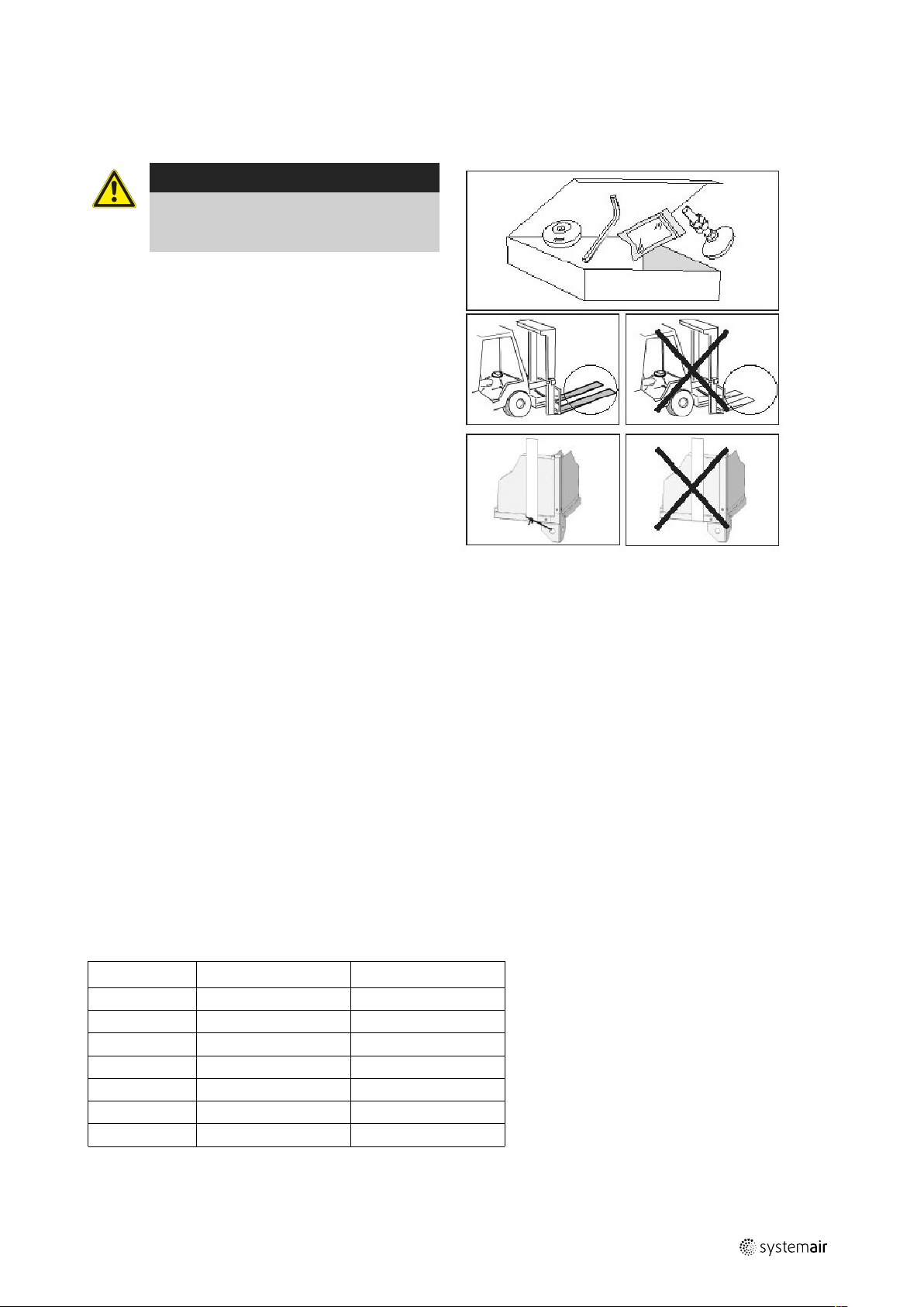
4.1 Transport and storage ..............................................................................................................4
4.2 Delivery/Unloading..................................................................................................................5
5 Prerequisites for Installation................................................................................................................5
5.1 Location and Space Requirements . ....................... ..... .. .................. ..... .. .................. ... .. ................5
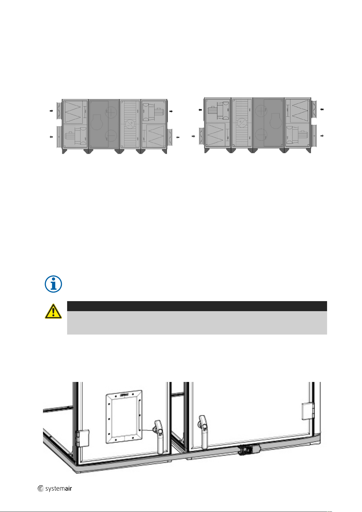
5.2 Positions and Placement ...........................................................................................................6
5.2.1 Positioning of compressors ............................................................................................6
5.3 Access to Power Supply............................................................................................................6
6 Installation......................................................................................................................................6
6.1 Electrical Connection ................................................................................................................7
6.1.1 Rotational direction of compressor(s)...............................................................................7
7 Commissioning ................................................................................................................................7
7.1 Before start-up .......................................................................................................................7
7.2 Control of Geniox Softcooler ......................................................................................................7
7.2.1 Power control.............................................................................................................8
7.2.2 Power limitation..........................................................................................................8
8 Service and maintenance ...................................................................................................................8
8.1 Cooling-technical maintenance...................................................................................................8
8.2 Electronic expansion valve.........................................................................................................8
8.3 Other maintenance..................................................................................................................9
9 Concluding Routines..........................................................................................................................9
10 Troubleshooting...............................................................................................................................9
10.1 Diagrams...............................................................................................................................9
10.2 Settings.................................................................................................................................9
10.2.1 High exhaust temperature or insufficient air volumes ..........................................................9
10.3 Electrical faults......................................................................................................................10
10.4 Faults in cooling technology .............. ..... ...... ..... ......... ..... ...... ..... ......... ..... ...... ..... ......... ............ 10
11 Description of Geniox Softcooler ........................................................................................................ 10
11.1 Geniox Softcooler Cooling section ............................................................................................. 10

212930 | A001
Contents
11.1.1 Batteries .................................................................................................................10
11.1.2 Control panel and automatic controls ............................................................................. 11
11.2 Function principle ..................................................................................................................11
11.2.1 Other regulation........................................................................................................11

Overview |1
1 Overview
The cooling unit can cause personal injury if installed or used incorrectly. Read the documentation for the product care-
fully before it is installed or commissioned.
1.1 Type label
Before calling your service representative, make a note of the specification and product number from the type label
(figure 1).
Fig. 1 Type label
Position Description
1Product name
2Order number
3Product electrical information
4Product serial number
5Product cooling information
6Manufacturer information
1.2 Warranty
For the assertion of warranty claims, the products must be correctly connected and operated, and used in accordance
with the data sheets. Further prerequisites are a completed maintenance plan with no gaps and a commissioning re-
port. Systemair will require these in the case of a warranty claim. The commissioning report is a component of this
document. The maintenance plan must be created by the operator, see section 8 Service and maintenance, page 8.
212930 | A001

2| Important Safety Information
1.3 Disposal and recycling
This product is compliant to the WEEE directive. When disposing the unit, follow your local rules
and regulations.
This product packing materials are recyclable and can be reused. Do not dispose in household
waste.
2 Important Safety Information
• Observe and respect local conditions, regulations and laws.
• Safety elements may not be dismantled, circumvented or deactivated.
• Wear protective equipment during all work in the vicinity of the unit.
• Do not allow children to play with the device.
2.1 Intended Use
• Abide by the system-related conditions and requirements of the system manufacturer or plant constructor.
• Keep all the warning signs on the device and in a legible condition.
• The device is not to be used by persons (including children) with reduced physical, sensory or mental capabilities, or
lack of experience and knowledge, unless they have been given supervision or instruction.
• The system should operate continuously, and only be stopped for maintenance/service.
• Make sure that filters are mounted before starting the unit.
• The refrigerant for this cooling unit is R410A and cannot be replaced with any other type of refrigerant without writ-
ten approval from the supplier.
2.2 Admonitions
Danger
• Make sure that the mains supply to the unit is disconnected before performing any maintenance or
electrical work!
• All electrical connections and maintenance work must be carried out by an authorized installer and in
accordance with local rules and regulations.
• Inspection doors must always be closed and locked with the corresponding key when the voltage is on.
Under no circumstances may the box be left with the door unlocked.
Warning
• This product must only be operated by a person who has suitable knowledge or training within this field
or carried out with the supervision of a suitably qualified person.
• Beware of sharp edges during mounting and maintenance. Use protective gloves.
• Delivery pipes are hot during and after operation, and contact with bare skin may cause burn injuries.
Warning
• Risk of injury due to rotating parts that have not come to a complete standstill after mains supply to the
unit have been disconnected.
Care for the Environment!
• The refrigerant must under no circumstances be released into the environment.
212930 | A001

Important Safety Information | 3
2.3 Declaration of Conformity
Manufacturer
Systemair UAB
Linų st. 101
LT–20174 Ukmergė, LITHUANIA
Office: +370 340 60165 Fax: +370 340 60166
www.systemair.com
hereby confirms that the following products:
Geniox Softcooler 12 Geniox Softcooler 14
Geniox Softcooler 16 Geniox Softcooler 18
Geniox Softcooler 20 Geniox Softcooler 22
Geniox Softcooler 24
(The declaration applies only to product in the condition it was delivered in and installed in the facility in accordance
with the included installation instructions. The insurance does not cover components that are added or actions carried
out subsequently on the product)
Comply with all applicable requirements in the following directives
• Machinery Directive 2006/42/EC
• Low Voltage Directive 2014/35/EU
• EMC Directive 2014/30/EU
• Ecodesign Directive 2009/125/EC
• RoHS Directive 2011/65/EU
The following harmonized standards are applied in applicable parts:
EN ISO 12100-1 Safety of machinery – Basic concepts, general principles for design – Part 1: Basic
terminology, methodology
EN ISO 12100-2 Safety of machinery – Basic concepts, general principles for design – Part 2:
Technical principles
EN ISO 14121-1:2007 Safety of machinery – Risk assessment – Part 1: Principles
EN 378-2:2016 Refrigerating systems and heat pumps - Safety and environmental requirements -
Part 2: Design, construction, testing, marking and documentation
EN 13857 Safety of machinery – Safety distances to prevent hazard zones being reached by
upper or lower limbs
EN 60 335-1 Household and similar electrical appliances – Safety Part 1: General requirements
EN 60 335-2-40 Safety of household and similar electrical appliances - Part 2-40: Particular
requirements for electrical heat pumps, air-conditioners and dehumidifiers
EN 50 106 Safety of household and similar appliances – Particular rules for routine tests
referring to appliances under the scope of EN 60 335-1 and EN 60967
EN 60 529 Degrees of protection provided by enclosures (IP Code)
EN 61000-6-2 Electromagnetic compatibility (EMC) – Part 6-2: Generic standards – Immunity for
industrial environments
EN 61000-6-3 Electromagnetic compatibility (EMC) – Part 6-3: Generic standards – Emission
standards for residential, commercial and light-industrial environments
The complete technical documentation is available.
Skinnskatteberg, 2019–02–06
212930 | A001

4| Technical Data
Mats Sándor
Technical Director
3 Technical Data
3.1 Unit size and Compressor(s)
One frequency-controlled compressor is supplied in all unit sizes.
Unit size Power
range
Cooling
capacity
kW
400V 230V
Compressor Power
frequency
converter
Main
swich
Compres-
sor
Power
frequency
converter
Main
swich
12 2 21 VZH044CG 10 kW 25 A VZH044CJ 10 kW 63 A
14 1 21 VZH044CG 10 kW 25 A VZH044CJ 10 kW 63 A
2 28,7 VZH052CG 11 kW 63 A VZH052CJ 11 kW 80 A
16
1 28,7 VZH052CG 11 kW 63 A VZH052CJ 11 kW 80 A
2 37,5 VZH065CG 15 kW 63 A VZH065CJ 15 kW 80 A
18
1 37,5 VZH065CG 15 kW 63 A VZH065CJ 15 kW 80 A
2 48,5 VZH088AG 15 kW 63 A VZH088BJ 15 kW 125 A
20 1 48,5 VZH088AG 15 kW 63 A VZH088BJ 15 kW 125 A
2 60,7 VZH117AG 18,5 kW 63 A VZH117BJ 18,5 kW 125 A
22
1 60,7 VZH117AG 18,5 kW 63 A VZH117BJ 18,5 kW 125 A
2 73,9 VZH170AG 22 kW 80 A VZH170BJ 22 kW 170 A
24 2 88,2 VZH170AG 22 kW 80 A VZH170BJ 22 kW 170 A
3.2 Refrigerant
The refrigerant used for Geniox Softcooler is R410A. This is initially filled at the factory, and the relevant quantity is indi-
cated on the cooling section. A long-term test is carried out with a vacuum to ensure that the cooling circuits are com-
pletely free of leaks before refilling with R410A.
4 Delivery, Transport, Storage
4.1 Transport and storage
Caution
• As for all equipment with electrical components, it is important that the cooling section is not stored
outdoors. Water and condensation may, in the worst case, lead to full short circuit and breakdown when
the power is connected. If the unit must be stored outdoors, ensure that it is protected against rain and
allow air to circulate to prevent condensation.
The Geniox Softcooler should be stored and transported in such a way that it is protected against physical damage that
can harm panels etc. It should be covered so dust, rain and snow cannot enter and damage the unit and its
components.
Important
• Use the packaging exclusively as transport protection and not as a lifting aid.
• When lifting with forklift trucks or pallet jacks, ensure that the forks go under the entire length of the box,
otherwise the underside of the box may be damaged. When using a crane, straps must be secured to
legs or any pallets; it is important that the straps do not slip during lifting.
• Be particularly aware that the cooling section may have a high centre of gravity if the compressor is
positioned at the top of the cooling section.
212930 | A001

Prerequisites for Installation | 5
4.2 Delivery/Unloading
The appliance is delivered in one piece containing all necessary components, wrapped in plastic on a pallet for easy
transportation.
Warning
When opening the transport packaging, there
is a risk of damage from sharp edges, nails,
staples, splinters etc.
Checking delivery
• Check the packaging and the air handling unit for
transport damage. Any findings should be noted on
the cargo manifest.
• Check completeness of the delivery.
Verify that all ordered equipment are delivered before
starting the installation. Any discrepancies from the or-
dered equipment must be reported to the supplier of
Systemair products.
Unpacking
• Unpack the product carefully.
• Check the air handling unit for obvious transport damage.
• Only remove the packaging shortly before assembly.
• Beware of sharp edges during mounting and maintenance. Use protective gloves.
5 Prerequisites for Installation
To ensure a proper and fail-free operation, it is important that the unit is installed according to these instructions.
5.1 Location and Space Requirements
The air handling units are intended for the transport and treatment of air between -40 °C and + 40 °C The units are ex-
clusively for comfort ventilation. The units are not for environments that exceed the corrosion class C4 according to EN
ISO 12944-2 (motors are constructed for handling of air between -20 °C and + 60 °C).
If the unit is installed in a cold place it is important that the unit is not shut-off by the main switch. As long as the main
voltage is on the electrical cabinet will be kept warm also in cold climates.
For service/inspection, a minimum measurement is required in front of the unit, corresponding to the door width of the
box. A space corresponding to the depth of the unit is required when replacing a condenser or an evaporator.
Unit size Door width Depth of the unit
12 600 1150
14 700 1350
16 700 1550
18 700 1750
20 700 1950
22 800 2150
24 800 2350
Avoid placing the unit against a wall, as low frequency noise can cause vibrations in the wall.
212930 | A001

6| Installation
5.2 Positions and Placement
Geniox Softcooler must always be placed on the warm side of the rotor. In other words, the cooling section has to be
placed between the rotor box and supply air fan box. Geniox Softcooler is produced in four positions: supply air down,
right and left, and supply air up, right and left.
See below for variations:
Supply air down (cooling section marked)
Supply air left Supply air right
5.2.1 Positioning of compressors
The compressor(s) always end up in the extract section. This is a great benefit as you then have good access to the
compressors from the filter side, regardless of the position of the unit.
5.3 Access to Power Supply
Voltage is 3-phase 400 V or 3 phase 230V. An N-conductor must be used with 400 V. Connection is made for Cu wire;
when feeding with AI, an AI/Cu transition is used. Depending on local rules and regulations, correctly dimensioned
earth-fault switches must also be used on power circuits for Geniox Softcooler. Earth-fault switches must be at least
100mA, and one attribute must be adapted to frequency converter operation (EMC-filter must be removed).
6 Installation
Note:
These installation instructions are only a supplement to the Geniox installation instructions; see our website.
Caution
It is important to make sure that the unit is completely level after installation, so that the condensation
water is drained from the tray. It is also important that the cooling section is not tilted more than 30° during
the entire transportation and installation process.
Geniox Softcooler cooling box is either supplied with fitted legs or on a pallet, depending on size.
1. Make sure that the sealing stripes and faces in-between the units halves are undamaged. Place the SoftCooler be-
tween the two air handling units parts and carefully push them completely together.
Note! To avoid any load and stress on the vertical profiles the strap must be carefully placed on the bottom profiles
of the unit when sections are pulled together.
212930 | A001

Commissioning |7
2. Press the sections hard together so that the rubber profiles are so flat that
the iron frames of the two sections are joined. Strap with tensioner is suit-
able for pressing the sections hard together.. Note! Do not place the strap
on the vertical profiles. The strap must be carefully placed on the bottom
profiles of the unit.
The sections must then be locked permanently together with 8 mm bolts
and nuts through the grey guiding and connection blocks. Systemair have
provided you the 8 mm bolts with round heads and nuts required to carry
this task out. An Allen key — size 6 — will be required.
3. Fit the supplied handles.
4. Adjust doors if necessary.
5. Fit the supplied water trap.
The height of the water trap is already adjusted to match the height of sup-
plied feet or base frame.
6.1 Electrical Connection
Warning
• Make sure that the mains supply to the unit is disconnected before performing any maintenance or
electrical work!
• All electrical connections and maintenance work must be carried out by an authorized installer and in
accordance with local rules and regulations.
Important
• Make sure that the voltage in the building is checked against the marking on the unit.
Geniox Softcooler is delivered completely wired, which means that the electrician is only required for connection to the
mains. Geniox Softcooler is delivered in all sizes, with an external safety switch, which cuts all phases and power supply
when switched off. This is the connection point for the electrician. The safety switch is not fixed in place on delivery
due to transport. The safety switch must be fitted on the front of the unit. Wires from the cooling section are routed to
the safety switch.
6.1.1 Rotational direction of compressor(s)
On Geniox Softcooler with one compressor, the rotational direction of the compressor is taken care of using a frequency
converter and rotational direction is independent of the phases of the main switch.
Note:
Unit, Geniox Softcooler and any electrical batteries are made for separate power supply, which is basically
sensible considering that these are high currents and require cables with a large cross-section. However, if
desirable, it is possible to pull one main cable out and divide conduits at the unit. Dimensioning of the
conduit can also be drawn according to either the unit + electrical battery or unit + Geniox Softcooler, or
according to which has the greatest power. This is possible as there is never simultaneous acceleration for
the electrical battery and cooling.
7 Commissioning
7.1 Before start-up
• Correct voltage connected.
• Safety switches and fuses on.
• Visual check of the unit, no loose objects, everything electric connected.
• Drain trap fitted.
7.2 Control of Geniox Softcooler
The Geniox Softcooler cooling section is controlled as needed from the main controller.
212930 | A001

8| Service and maintenance
7.2.1 Power control
The compressor (CPR) are step-less controlled between, in the frequence converter (FC), set minimum and maximum
frequency.
7.2.2 Power limitation
The frequency converter (FC) is continuously sensing the condensing pressure via the high pressure sensor (HPS) and
gradually slows down the speed of the compressor (CPR), if the pressure exceeds the set limitation value. This is done
to avoid a high pressure alarm.
8 Service and maintenance
8.1 Cooling-technical maintenance
Danger
• Make sure that the Mains supply to the unit is disconnected before performing any maintenance or
electrical work!
• All electrical connections and maintenance work must be carried out by an authorized installer and in
accordance with local rules and regulations.
Caution
• Operation in the refrigerant cycle and handling refrigerants must be performed by certified personnel.
Care for the Environment!
• The refrigerant must under no circumstances be released into the environment.
An annual inspection, service and check of the cooling technology is required. This needs to be carried out more often
in relation to any special conditions to which the unit is exposed or any local laws and regulations. This is a requirement
for the warranty conditions to be valid.
Suggestions for checks may include:
• Drain trap and draining from tray.
• Any abnormal noises from the compressor(s).
• Loose clamps for fastening pipes and components.
• Oil leaks from pipes or compressor(s).
• General cleaning, vacuuming and if necessary washing using detergent.
• Any corrosion on soldering or pipes.
• Checking for leaks in the cooling circuit.
• Connection of manometer for reading pressure.
• Any refilling with refrigerant R410A.
• Visual checks in sight glass.
• Any replacement of dry filters.
A manometer can be connected from the control panel during operation to achieve normal operating conditions. De-
tailed written reports must be made and handed to the person responsible for keeping a log.
8.2 Electronic expansion valve
The expansion valve is one of the most important components of the cooling system. This is adjusted at the factory and
superheating is 5K.
Warning
If there are any leaks in the refrigerant circuit, Systemair must be contacted for further handling.
212930 | A001

Concluding Routines | 9
8.3 Other maintenance
Geniox Softcooler does not require any maintenance other than the annual service. During this service, things to be
checked in addition to the cooling technology should include:
• Tightening of clamps in the cabinet.
• Measuring power consumption.
• Cleaning.
• Review settings and set points.
• Check vibration dampers.
Warning
• Frequency converters must not be touched configured. Converter settings are made at the factory, and it
is important that the parameters are not changed without consultation with Systemair. This could have
critical consequences for compressors and the warranty may be invalidated.
Also see the more detailed maintenance instructions supplied with the unit. All technical data for Geniox Softcooler is
supplied and is placed in the inside of the control panel cabinet. The test diagram from the factory, instructions for in-
stallation, maintenance and operation, connection diagram and other documents are also supplied with the unit in a
plastic wallet.
9 Concluding Routines
Perform the following procedures before leaving the site:
1. Ensure that the product is operational and that no alarms are active.
2. Collect all tools.
3. Inform the appropriate person that work is finished.
4. If applicable, close and lock the cabinet.
5. Follow the procedures for the return and disposal of replacement parts and the disposal of packing.
10 Troubleshooting
10.1 Diagrams
For troubleshooting use the supplied connection diagram; the diagram can also be downloaded from www.systemair.
com.
Potential faults are divided into four main categories in practice:
• Incorrectly set parameters and set points on commissioning.
• Insufficient air volume or abnormally high exhaust temperatures.
• Electrical faults.
• Faults in the cooling technology.
As a starting point, it is sensible to begin with the first two categories.
10.2 Settings
To be able to localize the fault easily, ensure that there is a cooling need from the main controller. If external start relay
is activated and reference signal (0-10V) is available, but cooling unit does not start up, the fault is located in the Geniox
Softcooler control box or in the cabling between control box and the main controller.
10.2.1 High exhaust temperature or insufficient air volumes
Check the technical calculations for the unit and see which air volumes the unit is calculated for. The problem that may
occur is that the condenser cannot get rid of the excess heat, and the high-pressure pressostat trips. Increase the set
air volume. The temperature of the exhaust is, as a starting point, dimensioned for max. 25,4 °C to the condenser; at
higher temperatures the cooling capacity is gradually reduced by the control to avoid that the unit is stopped by the
high-pressure pressostat. Significantly higher temperatures can lead to problems. The same problem solution as above.
212930 | A001

10 | Description of Geniox Softcooler
10.3 Electrical faults
If compressor start relay have been triggered in the unit cabinet, but the compressor(s) do not start, check the cabling.
The control for the cooling equipment is located in the cooling box; check that operation/alarm relay is activated. This
should be activated when voltage is switched on. If this is not activated, the fault is located in the following:
• High-pressure pressostat.
• Low-pressure pressostat.
• Fault output on converter.
High-pressure pressostats has manual reset and low-pressure pressostats have an automatic reset. Also check whether
there are any fault alerts in the converter display; see the manual supplied for this. If the relay has been activated, but
there is still no operation, check the start relay for the compressor. This relay is activated according to cooling need, and
follow the relays in the main controller cabinet. Check the relay and cabling to it in the event of faults. If relay is acti-
vated and the compressor do not operate see chapter 10.4.
10.4 Faults in cooling technology
Important
Before carrying out any work on the cooling technology within the warranty period, Systemair must be
contacted first, if necessary with any requests for covering costs.
Only authorised cooling companies may carry out work on the cooling circuit. A manometer should be connected and
the pressure checked. The temperatures of the different processes are also checked. Typical faults may be:
Compressor cuts out at low-pressure pressostat:
• Not enough refrigerant
• Insufficient air volume
• Electronic expansion valve defect
• Pressostat defect
Cuts out at high-pressure pressostat:
• Too much refrigerant
• High exhaust air temperature
• Pressostat defect
Freezing of evaporator:
• Electronic expansion valve defect
• Not enough air to the battery
A leak search is to be carried out when leaks are suspected, and during the annual inspection.
11 Description of Geniox Softcooler
11.1 Geniox Softcooler Cooling section
The Geniox Softcooler cooling section is a complete unit for a comfort cooling in air handling systems. In other words,
all electrical and pipe work is completed at the factory, tested and ready for installation. Unit is made from 60 mm Roc-
wool in a sandwich construction consisting of two aluzinc 185 steel plates. (Corrosion class C4).
On the front of Geniox Softcooler there is a large door for easy access to the components. There is also an integrated
control display of frequency converter and control panel door for easy access and inspection during operation. The sec-
tions come in seven different sizes and 12 power variants, all Geniox compatible.
11.1.1 Batteries
The batteries are already fitted in the box with all pipe connections complete. Evaporator and condenser batteries are
mounted on the same side in the box, so that the piping between the batteries is tidy and service-friendly in terms of
access during a service. The batteries fit the unit’s cross-section and use all available area in the air flow. This ensures
low speed and low decrease in pressure. Carry-over of condensation is thus eliminated.
The DX battery is placed in a drip tray to drain condensation. The tray has an external connection for a drain trap.
212930 | A001

Description of Geniox Softcooler | 11
Caution
It is important that the supplied drain trap with ball is fitted before commissioning.
11.1.2 Control panel and automatic controls
The automatic controls cabinet is supplied as an integrated part of the cooling box, with a door for inspection and serv-
ice work. This is possible to access during normal operating conditions for the unit. There are also nipples for refilling
and checking the pressures in the cooling circuits. The cabinet is equipped with an approved control panel lock and must
only be opened by authorised personnel.
11.2 Function principle
1
2 7
6
98
10 5 3 10
4
The main components of the cooling system are:
1. Condenser battery
2. Evaporator battery
3. Compressor
4. High pressure switch
5. Low pressure switch
6. Electronic expansion valve
7. Filter drier
8. Sight glass
9. Ball valve
10.Angle valves
The cooling process is either carried out using one compressor. When required, compressors starts so that the refriger-
ant is compressed and transported to the condenser; the refrigerant is cooled in the condenser using extract air and
then takes on liquid form. The refrigerant then continues to the expansion valve, and reduces pressure and temperature
over that, before continuing to the evaporator (DX battery). The liquid evaporates in the DX battery and simultaneously
cools the external air. The refrigerant then moves on to the suction side of the compressor and the process is repeated.
11.2.1 Other regulation
Geniox Softcooler is always equipped with a frequency-controlled compressor, i.e. the cooling effect is adapted to the
need, either due to variable (low) air volumes or variable (low) outdoor temperatures, or a combination of these. This
ensures a more stable operation and energy-saving cooling in relation to ON/OFF solutions. Regulation of the compres-
sor(s) is thus as follows:
When system gets start signal, the compressor will ramp up quickly to 100Hz and work that stage for certain amount of
time. After time passed, system will start to regulate compressor speed according to reference signal from main con-
troller (0–10V).
In case of alarm, either from the pressostats or frequency converter, frequency converter will stop and alarm output will
be activated.
In case of alarm, see chapter 10 in this document.
212930 | A001

Complete cooling unit for Geniox · Installation and Service · 212930 · en_GB · · A001
Systemair UAB
Linų st. 101
LT–20174 Ukmergė, LITHUANIA
Phone +370 340 60165
Fax +370 340 60166
www.systemair.com
This manual suits for next models
7
Table of contents
Other System air Accessories manuals