Timeguard ECO18P User manual


SECTION ONE
GENERAL INFORMATION
This bulkhead features an integral daylight sensing photocell which will automatically switch the
light on at dusk and off at dawn or at a time set by the user.
Unit is for indoor or outdoor use. Unit must be mounted as a fixed luminaire, and is not suitable
for portable use.
PARTS INCLUDED
- Low Energy Bulkhead c/w Dusk/Dawn sensor
- Instruction manual. Please keep safe for future reference.
- Accessory Pack including screws and wall plugs
- 18W PL-C 4 pin low energy lamp.
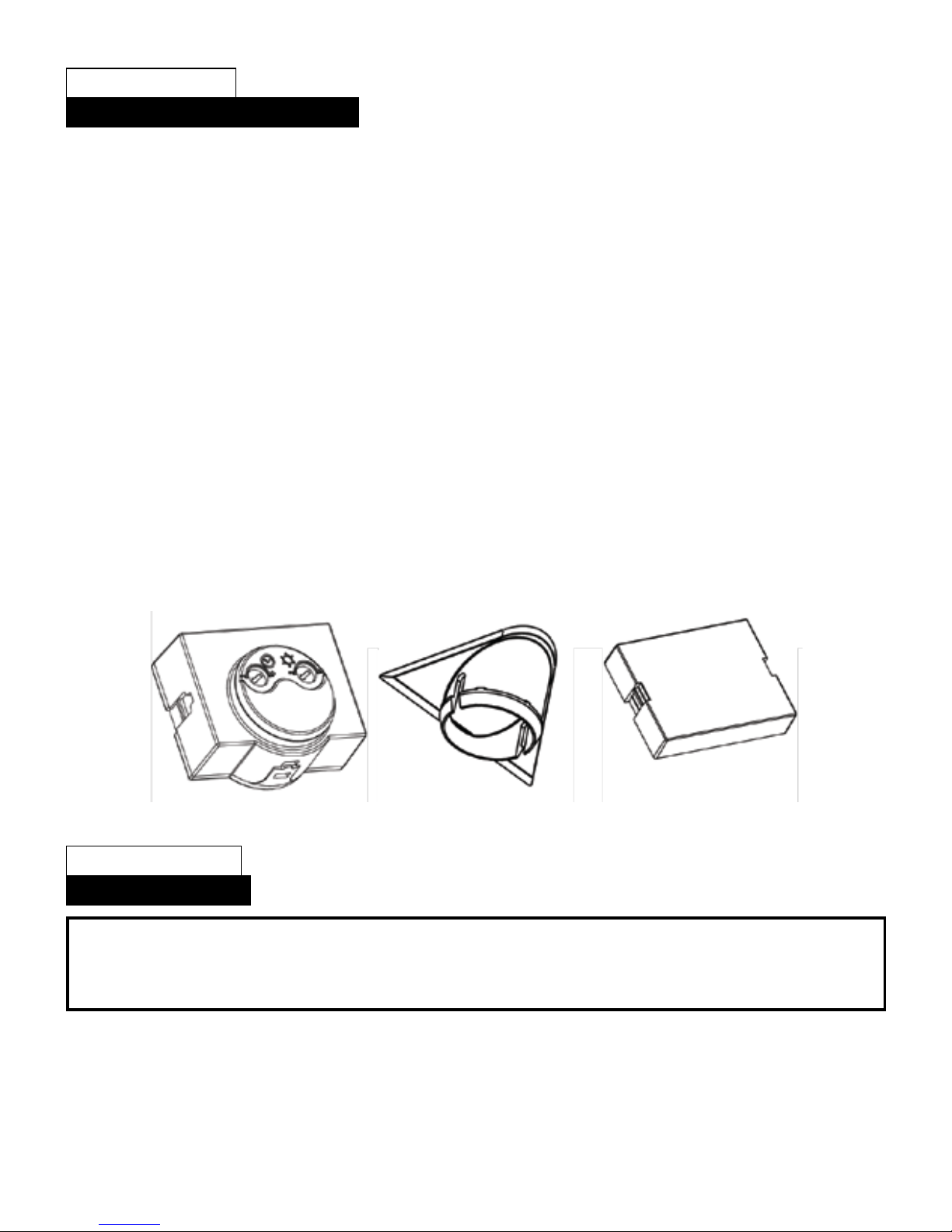
- Movable Dusk/Dawn Sensor module. (see image 1 below)
- Movable sensor aperture cover (see image 2 below)
- Movable Internal sensor circuit board cover (see image 3 below).
TOOLS & PARTS NEEDED
- 3 flexible core cable (1.0mm² or 1.5mm²)
- Electric/hand-held drill & bits
- Terminal or Electricians screwdriver
- Wire cutters
Do not attempt to install during wet weather, if you are suffering from nausea or dizzy spells or
onmedication with similar side effects.
1 Dusk/Dawn Sensor Module 2 Sensor aperture cover 3 Internal circuit board cover
SECTION TWO
INSTALLATION
SELECTING THE LOCATION
The unit can be mounted horizontally or vertically on the wall or over a door see diagram A. The
unit features a movable sensor module (1) which can be placed in either horizontal or vertical
orientation.
Also a sensor aperture cover (2) is provided to be fitted in the unused aperture based on your
chosen application.
*** IMPORTANT ***
Switch off the electricity at the fuse box by removing the relevant fuse or switching
off the circuit breaker before proceeding with the installation.
Downloaded from Elcodis.com electronic components distributor

After choosing a suitable location (see previous section) install the unit as follows:
The unit is suitable for connection to a 240 V ac 50Hz electricity supply. It is suggested that 3-core
round flexible cable of 1mm² or 1.5mm² gauge is used. An internal switch should be installed to
switch the power to the unit ON & OFF. This allows the unit to be easily switched off when not
required or for maintenance purposes.
It is recommended that the circuit is protected by a 5A max fuse or circuit breaker.
It is recommended that this product is connected to fixed wiring only.
To assemble the unit, decide on the orientation of your typical application. See diagram A
Open the front cover by inserting a small screwdriver into the slot at the top of the unit. A clip will
be released and the cover can be removed from the base.
VERTICAL MOUNTING (Diagram C).
Position the unit in the desired position based on the location of the incoming power cable.
Using the unit as a template, mark the position of the mounting holes.
Ensure the sensor module and circuit board cover are fitted in the locations shown.
FAILURE TO FIT THE SENSOR COVER CAN COMPROMISE SAFETY LEGISLATION.
Note the "UP" ident on the inside of the wall plate.(Diagram C).
Drill the holes, insert the wall plate into the holes.
PIERCE AND PASS THE CABLE THROUGH THE GROMMET BEFORE SECURING THE UNIT TO THE WALL.
It is recommended that the grommet is pierced with a screwdriver to ensure a better seal.
Fix the unit plate to the wall.
HORIZONTAL MOUNTING (Diagram D).
Position the unit in the desired position based on the location of the incoming power cable.
Using the unit as a template, mark the position of the mounting holes.
Ensure the sensor module and circuit board cover are fitted in the locations shown.
FAILURE TO FIT THE SENSOR COVER CAN COMPROMISE SAFETY LEGISLATION.
Note the "UP" ident on the inside of the wall plate.(Diagram D).
Drill the holes, insert the wall plugs into the holes.
PIERCE AND PASS THE CABLE THROUGH THE GROMMET BEFORE SECURING THE UNIT TO THE WALL.
It is recommended that the grommet is pierced with a screwdriver to ensure a better seal.
Fix the unit to the wall
Remove the cable clamp, feed the incoming cable under the cable clamp and secure. Do not
overtighten the cable clamp as it could damage the cable insulation (Diagram E).
CONNECTION
Connect the cable to the terminal block on the unit as follows (see diagram E):
NEUTRAL (Blue) N
EARTH (Green/Yellow)
LIVE (Brown) L
Ensure all connections are secure.
Remove the bulb from its packaging and fit into the lampholder. Ensure the bulb is fully secured into
the lampholder.
Fit the front cover as reversal of removal.
Fit the sensor aperture cover to the front cover. The sensor aperture cover is an extremely tight fit
into the front cover to maintain protection against water. The sensor aperture cover will fit with a
loud audible click, and will look similar to the engraved features on the opposite edge.
FAILURE TO FIT THE SENSOR COVER CAN COMPROMISE SAFETY LEGISLATION.
Installation is complete!
Downloaded from Elcodis.com electronic components distributor

SECTION THREE
OPERATION AND TESTING
SETTING UP FOR AUTOMATIC OPERATION
The adjustment controls on the unit (diagram F) should be set as follows.
The TIME control determines how long the lamp remains illuminated after activation.
There are 5 designated “time on” settings O (or off), 2, 4, 6, 8 hours and dusk/dawn.
These settings allow the lamp to illuminate for the designated time on period after darkness falls
and the unit is activated.
If you require the lamp to be illuminated all night, set the time control fully clockwise to “Dusk/
Dawn”. The unit will then remain on until the following morning when the lux level increases
enough to switch the unit off during the day.
The DUSK (LUX) control determines the level of darkness required for the unit to start
operating.
The setting is best achieved by the procedure below:
Set the DUSK control knob fully anti-clockwise and the Time control to the required
number of hours or dusk/dawn (do not leave in the O (off, fully anti-clockwise) position).
Wait until darkness falls.
When the ambient light level reaches the level of darkness at which you wish the lamp to
become operative (ie. At dusk), SLOWLY rotate the control in a clockwise direction until a point
is reached where the lamp illuminates. Leave the control set at this point.
At this position, the unit should become operative at approximately the same level of darkness
each evening. Observe the operation of the unit. If the unit is starting to operate too early (ie.
when it is quite light), adjust the control slightly anti-clockwise. If the unit starts to operate too
late (ie. only when it is very dark), adjust the control slightly clockwise.
Continue to adjust until the unit operates as desired.
MANUAL OVERRIDE MODE
The light can be switched on for longer time periods by use of the Manual Override Mode.
This can be activated at night by using the internal wall switch or circuit breaker supplying the
unit.
Please note:- The unit CANNOT be operated in Manual Override Mode during daylight hours. If
you want to test this function when installing the unit, this test must be carried out after dusk
when the unit has become operational.
To activate Manual Override Mode:-
Switch the internal wall switch/circuit breaker once (off/on) within 1 second.
The unit will now illuminate continuously until dawn or until it is switched back into Auto Mode.
To de-activate Manual Override Mode (ie. switch the unit back into Auto Mode):-
Switch the internal wall switch/circuit breaker once (off/on) within one second. The unit will
return to its Auto mode and will operate as set up initially.
Downloaded from Elcodis.com electronic components distributor

SECTION FIVE
NO USER SERVICEABLE PARTS INSIDE
TROUBLESHOOTING GUIDE
PROBLEM
❏The floodlight will not
operate at night.
❏Unit activates during the
daytime.
SOLUTION
The level of ambient light in the area may be too bright to
allow operation at the current DUSK setting. During the hours
of darkness, adjust the DUSK control slowly clockwise until the
lamp illuminates. Refer to previous section for more details.
Adjust the lux setting anti-clockwise to lower the level of
ambient light required for activation.
SECTION FOUR
TECHNICAL SPECIFICATIONS
Power Supply
Lamp Type
Time On
Lux Level Adjustment
Environmental Protection
EC Directives
240V AC ~ 50Hz
240V 18W 4pin (GX2Dq-2) Low Energy lamp
2, 4, 6, 8 hours from dusk or dusk/dawn
Day & night or night only operation
IP44 (suitable for outdoor use)
Conforms to 73/23/EEC, 89/336/EEC
If you experience problems refer to Troubleshooting Guide.
If problems still exist, do not immediately return the unit to store.
Telephone the Timeguard Customer Helpline
020 8450 0515
Qualified Customer Support Co-ordinators will be on-line to assist in resolving your query.
In the unlikely event of this product becoming faulty due to defective material or
manufacture, within 1 year of the date of purchase, please return it to your supplier
with proof of purchase and it will be replaced free of charge. In the second and
third years or any difficulty in the first please contact our helpline on 020 8450 0515.
Downloaded from Elcodis.com electronic components distributor

Table of contents
Other Timeguard Accessories manuals


