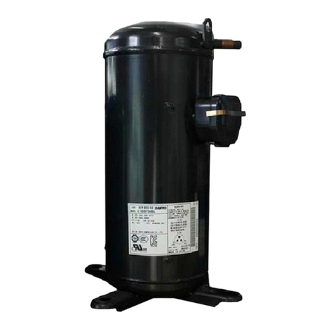
Tecumseh AG User manual

AG/TAG
2
SP6024 ind C
Please read this notice in full.
The implementation, operation, maintenance and end-of-life management of products involves following strict rules in accordance
with existing standards and best practices. Current standards and legislation should be respected in the country where the
compressor is installed, and the rules of good refrigeration and electrical practice should be applied.
These instructions cover the main points of the ISO Standards. The EN guidelines and standards described below prevail in the
European Union.
Caution: Safety First
Never energize the system unless
1- The protective cover is securely fastened and
2- The compressor is property connected to ground
1. Statements of compliance and incorporation
These refrigeration compressors are designed to be incorporated into machines in accordance with the Machinery Directive
2006/42/EC. They comply with the Low voltage Directive 2014/35/EU and the PED Directive 2014/68/EU. They also meet the
requirements of the Statutory instruments for the UK market.
Their commissioning is only permitted if they have been assembled in accordance with the following instructions, and if the machines
comply with existing regulations.
In the case of the use of A2L-classified fluids following ISO 817, follow the safety rules specific to flammable fluids. The compressors
will be installed, maintained in accordance with ISO 5149 or EN 378 or EN60335-2 safety standards
The designations of the compressors in question are AG****U for R1234yf, AG****N for R455A and AG****P for R454C and R454C.
2. Safety and risks associated with the implementation and use of flammable refrigerants, classified as Category A2L
2.1. Flammable refrigerants:
The fluids are heavier than air; they will naturally migrate towards the bottom of the installation in the absence of ventilation"
Their main characteristics from ISO817 or supplier data are given as an indication in the table below:

AG/TAG
3
SP6024 ind C
Refrigerant R1234yf R455A R454C
Safety class A2L A2L A2L
Lower flammability limit
under normal conditions
in volume/volume
according to ISO 817
% 6,2 % 11,8% 6,2%
Lower flammability limit
under normal conditions kg/m3
0,289 0,431 0,293
Practical limit 20% LFL g/m357,8 86 59
Auto-ignition
temperature
(according to ISO 817)
°C 405 473 > 400
Never use the product without consulting the Safety Data Sheet (S.D.S.) available from your refrigerant provider.
2.2. Scope of application of standards for refrigeration systems using flammable fluids
Provided that local regulations allow it, the quantities of flammable fluids that can be used in refrigeration systems are defined in
the standards for these products, such as EN 60335-2-40, EN 60335-2-89 or EN 378.
*For higher loads, please refer to the requirements of Standard EN 378-1
2.3. Preventing the formation of potentially explosive zones
The use of flammable fluids may present a risk of ignition in the event of a leak. It is therefore important to ensure that the refrigeration
system design and compressor ventilation do not allow for the creation of an explosive zone.
2.4. Staff Qualification
It is essential that Standard EN 378-3 is observed during installation and Standard EN 378-4 during maintenance works.
To maintain and repair the installations, staff must be authorised to handle refrigerants and correctly trained in the handling of
flammable fluids in order to avoid the risk of the formation of an explosive atmosphere.
Consequently, staff must know the tools, the transportation procedure for the compressor and refrigerant, and the safety precautions
and regulations that apply to maintenance and repair work. Not use ignition sources while handling flammable refrigerants.
2.5. Protection of the compressor's electric terminal
The disintegration of the insulation (glass bead) on a compressor power station due to physical shock or strong heating could create
a hole through which the refrigerant and oil would escape. On contact with a spark, this mixture could ignite. Any accidental damage
to the terminal during operation results in the compressor being scrapped.
The installation of the terminal cover protects the tripolar terminal from shocks in normal use.
Also, especially when using flammable fluids, Tecumseh advocates the use of a security system to protect users, interveners and
installation. The system will be able to detect a spike in intensity that could melt the insulation (the phenomenon of "pin venting"),
and will thereby cut off the compressor's power supply.
Since the compressor is not equipped with protection in the case of an external fire, it is appropriate for the equipment manufacturer
to secure the installation to prevent a fire. Adequate means of purging and protection against exceeding permissible limits (see
conditions on the PED label) must also be provided.
Compressors should not be installed in a corrosive or dusty environment.

AG/TAG
4
SP6024 ind C
3. Specifications - Marking compressors in the AG range
AGP **** and TAGP **** products are intended for parallel assembly. AGD and TAGD are assembled as a duo, and AG-TR and TAG-
TR as a trio.
3.1. Identification label and designation:
AG****N, TAG****Z and C compressors are grade II certified under the 2014/68/EU PED Pressure Equipment Directive.
AG****P compressors are grade III certified under the PED Pressure Equipment Directive 2014/68/EU.
(Reference free internal volume: 11.6L)
Labels contain the following information:
Ref. Designation
a Voltage
b Frequency
c Number of phases
e Liquid refrigerant
f Compressor designation
g Serial number
h Maximum allowable pressure – 1.1*PS
i Min/max temperature
j Maximum ambient temperature
k Notified organisation registration number
l Manufacturing and testing date
m Free volume
AJ****P compressors are qualified for R455A and R454C
AG **** N
compressors are qualified for R134a and
R1234yf.
They carry a yellow warning logo as shown opposite:

AG/TAG
5
SP6024 ind C
In the case of multi-fluid compressors, the Printed PS pressure = at the pressure of the fluid + binding to Ta maxi
Fluids PS (b) PED category
R-404A
20.1
II
R-452A
21
II
R-449A
20.4
II
R-448A
20.4
II
R-407C
19.1
II
R-455A
21.5
III
R-454C
18.4
III
R-1234yf
10.8
II
R-22
16.7
I
R-513A
11.5
I
R-134A
10.9
I
3.2. Specifications
The housing of the compressors in the ‘AG’ family is subject to the low pressure of the refrigeration system.
In line with the PED and in order to ensure the best level of quality of its products at all times, Tecumseh tests each compressor on an
assembly line at a pneumatic pressure which is greater than or equal to the requirement 1.1 x PS, regardless of the refrigerant indicated
and based on the calculation of the most restricted refrigerant, R455A.
For information: 1.1 * PS (46°C sat) = 24 bar rel for R455A.
Additional explosion tests are also performed periodically.
4. Transport - handling:
At the factory exit, the compressor is loaded with oil and nitrogen (0.3 to 0.5 bar). It does not contain any refrigerant during delivery.
For information about compressor delivery, refer to your terms of sale. Check the good condition of the equipment at its reception.
(Good exterior appearance, no shock or deformation) especially on the connection terminal.
Do not hold the compressor by the tubes but by its lifting ring intended for this purpose. Refer to our technical documentation to find
out which storage and transport positions are allowed.
The recommendations for transporting systems loaded with refrigerants are the responsibility of the manufacturer of these systems.
5. Recommendations related to the use and assembly of the compressor in a refrigeration system:
In the case of operating with flammable fluids, installation must be designed on the basis of a risk analysis to avoid refrigerant
accumulation in the event of leakage in areas that are potential ignition sources.
-It is recommended to provide a device capable of detecting compressor over-intensity to prevent a spike in intensity that
could melt the insulation (“pin venting” phenomenon).
-Provide appropriate protections in line with local regulations to prevent the public, user or anyone with access to the
application from degrading the product.

AG/TAG
6
SP6024 ind C
-Also provide adequate signage for flammable fluids on the complete installation, so that the user or anyone with access to
the application is aware of the risks associated with their presence (putting in place standard pictograms preventing the risk
of flammability).
-Establish an appropriate way to alert the user that they need to call on a professional to manipulate the application.
5.1. Maximum allowable pressure
Tecumseh compressors are designed to operate at a maximum ambient temperature of +46°C. Observe and comply with the specific
regulations to optimise the quantity of refrigerant in the installation and never exceed the maximum discharge pressure corresponding
to the maximum condensation temperature of the compressor's operation. The compressor housing should not be subjected to a
temperature below -35°C; the materials used would not guarantee sufficient mechanical characteristics.
5.2. Expansion element
Tecumseh recommends the use of thermostatic expansion valves.
5.3. Installation for the first commissioning
Tecumseh cannot be held responsible if the installation and maintenance do not comply with the instructions provided in this manual.
Current guidelines and regulations in force in the country where the compressor is installed, and the rules of the art for refrigeration
and electrical connections, must be complied with.
5.4. Location of the compressor and definition of refrigerant charge
5.4.1. Defining the refrigerant charge
The refrigerant charge should not exceed the amount that can be stored under high pressure. When it is likely to migrate into the
compressor during downtime, or when it is greater than 1.5 Kg, Tecumseh recommends the use of a casing heater and/or an non
return valve on the pressure pipe.
The return of liquid during transitional periods will be prevented by an anti-liquid receiver.
The maximum load of flammable fluids is defined in the product standards according to the volume in which the refrigeration system
is installed, its location and its type of occupation (not exhaustive).
5.4.2. Location of electrical components that create sparks in the case of the use of A2L flammable fluids
They must be located in a non-potentially flammable area. Tecumseh recommends installing them high up, and in a sufficiently
ventilated area.
5.4.3. Replacing the compressor
The compressor should not interfere with the movement of people, or the opening of doors or shutters.
The support receiving the compressor will be sufficiently resistant (base, squares, wall etc.). Check that the compressor level is
horizontal and that it is equipped with its silent blocks.
Be careful not to block the flow of air around the electrical components and compressor, to ensure its cooling.
5.5. Soldering, refrigeration connections
As a reminder, soldering can only be carried out on installations not loaded with refrigerants.
To keep the installation running smoothly, it is advisable to:
- Solder under dry nitrogen and keep any flames away from electrical equipment.
- Insulate the suction line up to the compressor entrance, to avoid condensation.

AG/TAG
7
SP6024 ind C
Cut and shape the tubes carefully, to prevent dust and metal particles from entering the system. Never use a saw. Use a bending tool
adapted to the diameter of the tube to avoid excessive restrictions.
Tecumseh recommends solder connections instead of “dudgeon-type” screwed fittings to limit the likelihood of leakage over time.
Screwed fittings on a flat surface via a joint are acceptable.
A leakage check is mandatory before commissioning.
5.6. Suction valve tightening torques
1- SAE 1/4’’ : 7 to 11 Nm
A - Empty or loaded coupling
B - Pressostatic connector
2- Square bit drive 1/4’’ : 6 to 13 Nm
3- Cable gland: 5 to 13 Nm
4- Connector 1’’1/4- 12 UNS : 114 Nm to 126 Nm.
Release the cable gland nut prior to handling the needle valve. Then retighten the
cable gland nut.
Other connection (optional) :
Angle connection to be screwed on the suction or discharge 1''1/4- 12UNF: 114 Nm to 126 Nm.
Oil equalization sub-assembly 5/8" - 18 UNF: 26 Nm to 30 Nm
Pressure equalization sub-assembly 1''3/4-12 UNF: 149 Nm to 162 Nm
1A
1B
3
2
4

AG/TAG
8
SP6024 ind C
5.7. Screwing the oil equalisation fitting for parallel compressors
Before connecting the oil equalisation tip of the TAGP or AGP compressors, tilt to a minimum of 10° as shown above.
5.8. Suspensions
All Tecumseh compressors come as standard with an external suspension set including shock absorbers and spacers. The role of these
shock absorbers is to reduce the transmission of vibrations generated by the compressor to the base on which it is attached. In order
to ensure this function properly, shock absorbers should not be constrained. For this, the washer pressing on the spacer must leave a
clearance of 1 to 4 mm from the top of the shock absorber.
In order to not distort the spacer, apply a tightening torque of between 8 to 13 Nm for the M8 screws.
5.9. Electrical connections
Electrical connections will be made before the refrigeration system is loaded with refrigerant.
To preserve the quality of the Tecumseh compressor and the safety of the installation and ensure their proper operation, it is
imperative to:
- Always wire the compressor when it is switched off.
- Validate the compatibility of the installation's power voltage with that of the compressor (see the nameplate).
- Validate the compatibility of the compressor's electrical drawing with that of the installation.
- Size the connecting cables (power, control) according to the characteristics of the installed compressor (see nameplate).
- Protect the power line and install a grounding line.
- Make electrical connections in accordance with the country's current regulations.
- Use the electrical components that come with the compressor, even if others seem acceptable.
10°

AG/TAG
9
SP6024 ind C
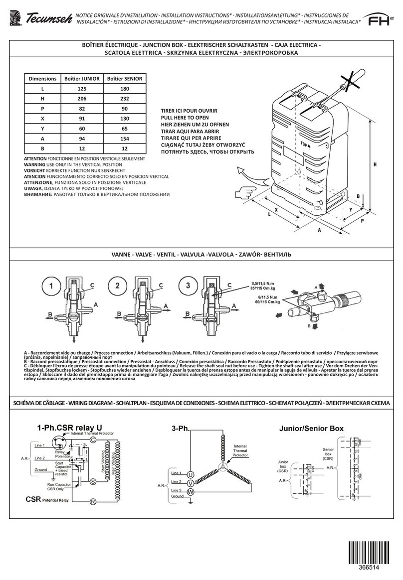
The electric box must always be fixed vertically.
Dimensions
JUNIOR box
SENIOR box
L
125
180
H
206
232
P
82
90
X
91
130
Y
60
65
A
91
154
B
12
12
5.10. Circuit sealing
Before loading with refrigerant, systematically search for leaks on all fittings, and seal them if necessary.
5.11. Evacuation
Evacuate the installation to reach a residual pressure of about 200 micrometres of mercury (0.27 mbar), guaranteeing a good quality
of vacuum. It is advisable to drain the HP and BP circuits simultaneously in order to reduce the operation time and ensure an identical
level of vacuum throughout the circuit.
6. Refrigerant charge, powering up and maintenance:
If the following manipulations are performed in potentially explosive atmospheres, Tecumseh recommends referring to Standard EN
378. Part 4 prescribes the general safety guidelines and provides guidelines for interventions in equipment using flammable
refrigerants.
6.1. General recommendations:
The electrical boxes will be properly installed and closed before loading the refrigerant and switching on installation.
HFO levels in the air will be monitored throughout the whole refrigerant charge and maintenance period.
Leak detection equipment will be calibrated to 20% of the LFL of the refrigerant.
The work area will be ventilated throughout the procedure.
6.2. refrigerant charge
The provisions in Parts 2, 3 and 4 of EN 378 must apply to prevent the risk of refrigerant emission during refrigeration system filling
and emptying operations.
Limit the refrigerant load so that the pressures are in the operating window defined by Tecumseh.
Never start the compressor if the vacuum is not broken in HP and BP.

AG/TAG
10
SP6024 ind C
The components will be grounded before starting the refrigerant charge.
Load the installation only with the refrigerant or one of the refrigerants for which the compressor was designed (see nameplate).
The refrigerant charge will always be in liquid form, to keep the mixture in the right place.
- Do not add any additives or dyes.
6.3. Risk of refrigerant overload
If the main parts of the compressor are submerged due to too much refrigerant, this can cause the compressor housing to split.
Immersion of the engine, connecting rod, piston and cylinder in the liquid creates a hydraulic blockage preventing the compressor
from starting this is therefore a blocked rotor situation.
If, for some reason, the compressor protector does not intervene quickly enough, a high current in the engine coil will create a rapid
rise in temperature. This will cause the liquid to vaporise and the pressure in the compressor housing to increase rapidly.
As an example of what not to do when charging a system with refrigerant, never leave the charging cylinder connected to the system,
even if the valve of the cylinder or that of the "manifold" is closed. If one of these valves leaks slightly, the system will be overloaded
with the risks mentioned above.
6.4. Checks when commissioning
- Calibrate electrical protective organs, adjust the set/cut points of the regulatory and safety organs.
- Fully open the service valves.
- Check the operation of the oil heater, if present.
Tecumseh compressors are protected by an external or internal protective organ, the principle of which is based on a
temperature/current combination. Like any protective body, it is normal for the compressor to shut off power when it is operating
outside the manufacturer's defined ranges.
When operating plans are stabilised, do the following checks:
-Tension and intensity absorbed by the compressor;
-HP and BP pressures from the installation;
-Overheating, undercooling, gas return temperature, discharge temperature;
-Search for leaks;
-Carry out a general inspection of the installation (cleanliness of installation, abnormal noise, etc.). Visually inspect the
refrigeration system (for example, according to the list listed in Annex G of EN378-2).
For installations operating with a flammable refrigerant, check if the leak detection equipment is working properly.
Do not add oil unless the pipes exceed 20 m; in this case, use the oil recommended by Tecumseh.
6.5. Maintenance
Tecumseh recommends securing the maintenance area in accordance with EN 378 Part 4
Below is a non-exhaustive list of recommendations:
-Obtain a permit for high-temperature work (if necessary);
-Ensure that no flammable material is stored in the work area and that there are no sparks in the work area;
-Switch off electrical appliances;
-Keep heat sources away to avoid explosions;
-If a heat source is present in the workplace, make sure a fire extinguisher is available;
-Ensure that the work area is properly ventilated, before intervening on the refrigeration system or before welding or tender
brazing work;
-Mark the work area to prevent entry of unqualified people;
-Ensure that the leak detection system used is spark-proof, secured appropriately or inherently safe
-Ensure that all maintenance personnel have been trained.

AG/TAG
11
SP6024 ind C
Wherever possible, the refrigeration system operating with a fluid classified as an A2L category will be transported to a workshop
adapted to its maintenance.
Check that the pressure of the refrigeration system will not be a danger factor during the intervention (projection of parts, refrigerant
etc.). The compressor can reach temperatures above 120°C in operation. Do not intervene in the compressor without protection.
IMPORTANT: If the detection system preventing a spike in intensity that could melt the insulation (pin venting) has intervened, do
not reset it. Replace the compressor following installation and commissioning recommendations (see Section 5).
6.5.1. Recovery of flammable fluids
-Use a recovery plant suitable for flammable fluids
-Identify the fluid in the cylinder and affix the flammability logo
-Do not mix refrigerants together.
6.5.2. Inerting the refrigeration system and precautions before soldering
-Ensure that a fire extinguisher is present nearby,
-Inert the system with nitrogen without oxygen (or air),
-The flow will be ventilated preferably outdoors.
6.5.3. Opening of the refrigeration system and replacement of components
IMPORTANT: Soldering is prohibited during operations on installations loaded with a flammable refrigerant. More generally, it is
imperative to prohibit any source of ignition (sparks, flames, hot springs) near the circuit.
After replacing components, crimped connections are an alternative to soldering.
6.5.4. Evacuation
For flammable refrigerants, check that the vacuum pump contactor is the only source of ignition.
Make sure the vacuum pump does not blow near an ignition source (empty pump switch, etc.).
An evacuation outside is recommended.
6.5.5. Replacing electrical components
-The electrical cabinets will be properly closed before refrigerant charging and restarting installation.
-Replace defective electrical components with similar references to ensure continuity of installation safety.
-Do not move electrical components.
Check regularly
-security and regulatory bodies;
-the states of the electrical and refrigeration connections (retightening, oxidation, etc.);
-the operating conditions;
-the compressor attachments on its support;
-how the oil heater works.
Look for leaks once a year, or according to local regulations.
Signage
The refrigerant used and its mass must be labelled, whatever they may be.
In the case of a fluid classified A2L, the flammability logo will be visible and readable.
6.6. End of life of the product
Fluorinated fluids will be recovered as imposed by the F-Gas regulation in the European Union.

AG/TAG
12
SP6024 ind C
Tecumseh also advises recycling the compressor oil and the compressor itself.
7. Warranty
For information on the compressor warranty, refer to the terms and conditions of sale.
In order to be able to continuously improve these products, Tecumseh reserves the right to modify these instructions without notice.
This manual suits for next models
1
Other Tecumseh Air Compressor manuals
Popular Air Compressor manuals by other brands

Elektra Beckum
Elektra Beckum Compressor Pump Mega 350 D Operating instruction
Wagan
Wagan 2014 user manual
California Air Tools
California Air Tools 15020C owner's manual
Draper
Draper DA25/206A instructions

ALUP Kompressoren
ALUP Kompressoren SCK 21 Maintenance and operating instructions
Craftsman
Craftsman 919.165520 owner's manual


