TeeJet Technologies Centerline 230BP User manual

Guidance Only Software Version 1.07
020-020-UK R0

CenterLine 230BP
020-020-UK R0
i
TABLE OF CONTENTS
CHAPTER 1 - INTRODUCTION.................................................................................................... 3
System Configuration.............................................................................................................. 4
Installation - Guidance ............................................................................................................ 4
CHAPTER 2 - SETUP ................................................................................................................... 5
Power Up Sequence ............................................................................................................... 5
Area Reset .............................................................................................................................. 6
Setup Mode............................................................................................................................. 6
Initial Setup Screen .......................................................................................................... 6
Boom Width ...................................................................................................................... 6
Boom Offset Direction ...................................................................................................... 6
Boom Offset Distance....................................................................................................... 7
Display Setup Mode................................................................................................................ 7
Display Setup Screen....................................................................................................... 7
Display Brightness............................................................................................................ 7
Display Contrast ............................................................................................................... 7
Display Background.......................................................................................................... 8
LED Spacing..................................................................................................................... 8
COM Port Setup ..............................................................................................................8
GPS Setup........................................................................................................................ 8
CHAPTER 3 - OPERATION ..........................................................................................................9
Power Up Sequence ............................................................................................................... 9
CL230BP Operation Reference Screens ................................................................................ 9
Navigation Screen - Mark A-B .......................................................................................... 9
Navigation Screen - Operation ....................................................................................... 10
Guidance Screen - Map Page ........................................................................................ 10
Bounded Area Screen .................................................................................................... 10
Operation Function Keys ................................................................................................ 11
Operations Screens........................................................................................................ 11
Guidance Operation - Modes................................................................................................ 11
Headland Circuit Guidance............................................................................................. 11
Straight A-B Guidance.................................................................................................... 12
Curved A-B Guidance..................................................................................................... 12
Circle Pivot Guidance ..................................................................................................... 13
Compass View/Return To Point...................................................................................... 13
A+ Nudge Feature .......................................................................................................... 13

Table of Contentsii
CenterLine 230BP
020-020-UK R0
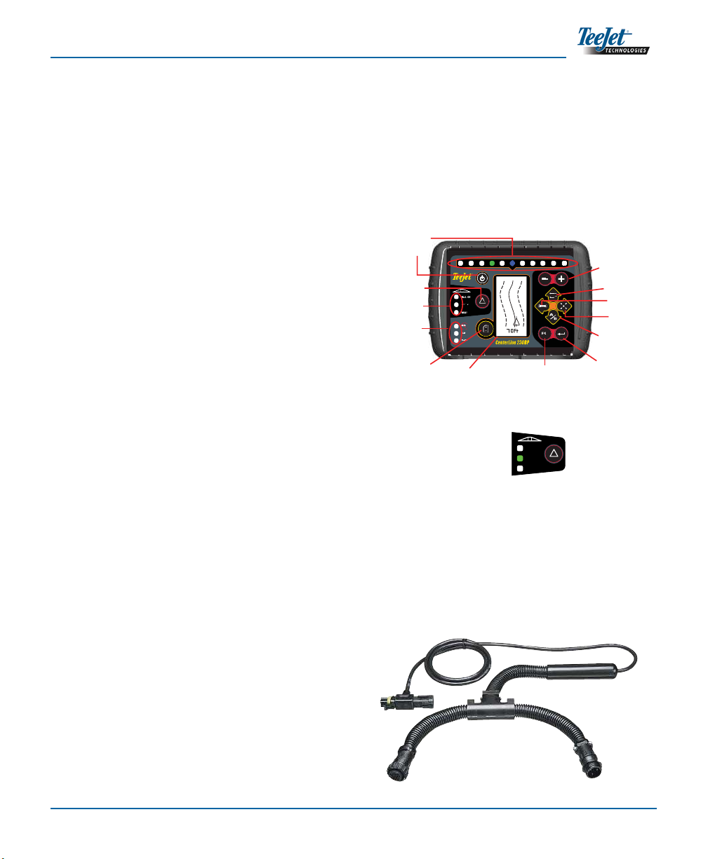
3
Tilt Gyro compensation is now available as an•
upgrade to the CenterLine 230 BP. For part
numbers and pricing, please consult your re-
gional TeeJet Technologies representative.
The upgrade includes the support of Field-•
Pilot Assisted Steering. Connection to the
SCM is now via CAN. Existing FieldPi-
lot 220 customers upgrading to FieldPilot
230 must arrange to exchange their SCM.
NOTE: The swath status bar is only active if a
smartcable is installed.
SMART CABLE - The Smart Cable is the link
between the CL230BP, the existing rate controller,
and the boom section valves. It allows the CL230BP
to control the boom sections automatically and is
necessary to allow for Automatic Boom Section
Control. For the user guide covering the additional
features with an added SmartCable, please
refer to CL230BP User Guide 020-034-UK R3.
ALL ON
AUTO
MAN
CHAPTER 1 - INTRODUCTION
This User Guide provides information for software
version 1.07.
The CenterLine 230BP (CL230BP) software 1.07
provides the following enhancements to the system:
Applied area now includes only the area under•
the active boom sections and acre counters will
accurately represent applied area. Prior calcu-
lations counted all area under the entire boom,
regardless of whether individual sections were
on or off.
Unapplied area is now considered “untreated”
•
and can be treated at a later time.
Boundary area is calculated and displayed as•
a result of a headland perimeter pass in head-
land circuit mode. This value is held in memory
through the next power cycle and is erased when
the user chooses to clear the memory and begin
application of a new area.
When a field boundary is created in headland cir-
•
cuit mode, a “No Spray” zone is created outside
of that field boundary. This boundary and “No
Spray” zone is held in memory through the next
power cycle.
Area information and as-applied data are now
•
updated and saved with greater frequency.
Drive Sensitivity (LED spacing on the lightbar)•
can now be changed in the system Setup menu.
A section width of “0.0” can now be entered.•
Contrast is now adjustable with the +/- keys•
during the startup splash screen. Once GPS
is attained, the +/- revert back to adjustment of
screen Brightness.
A system setting for “GPS Source” allowing a
•
devoted external source has been added. The
default GPS source is the internal GPS receiver.
DGPS LED activation will now cycle through a 2
•
minute delay for the purpose of stabilizing DGPS
performance. It is recommended guidance mode
operation begin after the DGPS LED is active.
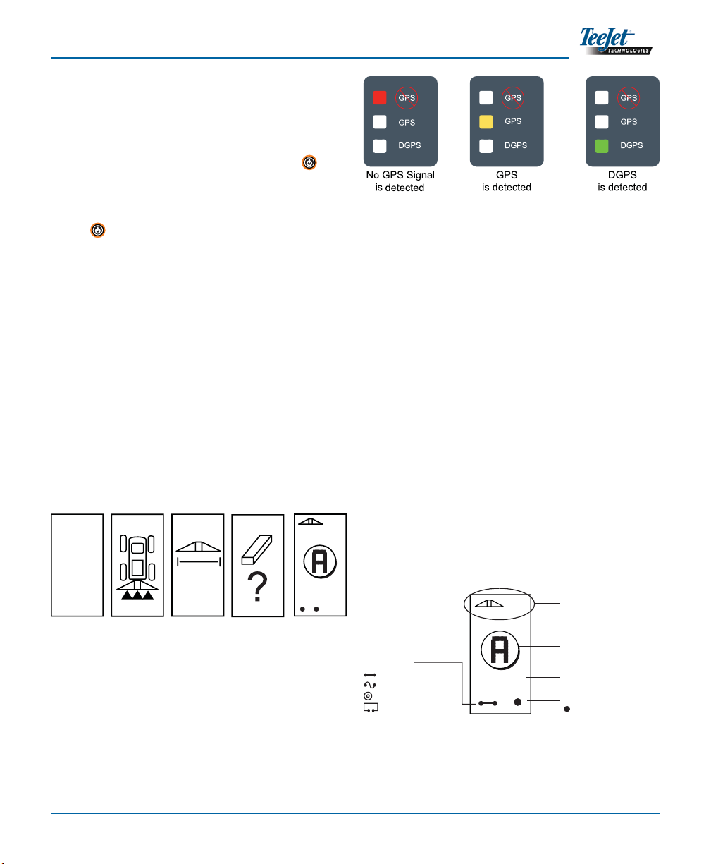
ESC
GPS
GPS
DGPS
ALL ON
AUTO
MAN
Power
Increase/Decrease
Swath Status Lights
GPS Status Lights
Change Page
Setup Mode
Escape Enter
Display
Return to Point
Mark A/B
Line
Guidance Mode
Lightbar
Swath Status
(Selects Mode)
Introduction4
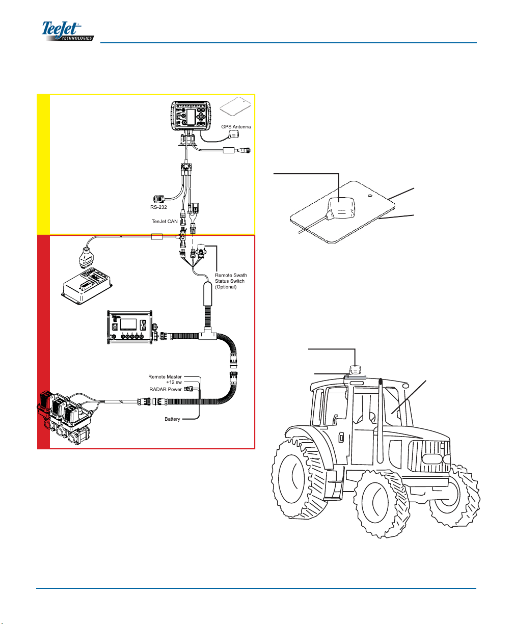
without SmartCable - ‘Guidance Only’with SmartCable
Installation - Guidance
Avoid mounting the antenna close to other electri-
cal installations (air conditioning equipment, radio
antennas, etc.). Avoid coiling excess antenna cable -
configure it in a “figure 8” shape and keep the cable at
least 30 cm (1 ft) from possible sources of electrical
interference.
System Configuration
65-05055
Metal Mounting Plate
60-10081
VelcroTM
GPS Antenna
Position the GPS antenna in the center of the vehicle
at the highest point with a clear view of the sky. If the
tractor cab is non-metallic, mount the metal plate in
the center of the vehicle at the highest point with the
VelcroTM strips and place the antenna on the plate.
Route the antenna cable carefully to avoid damage
and possible electrical interference.
Metal plate
Antenna
GPS Speed Output
External GPS Receiver
Input/Output
GGA 5 Hz
VTG 1 Hz
19200 Baud rate
Rate
Controller
Harness
SmartCable
Adapter
Harness
TeeJet 844-E
Rate Controller
Valves
Console
Power
Metal Mounting Plate
65-05055; 60-10081 VelcroTM
Speed Cable
CAN
90-02536
Optional Tilt Gyro Module kit
Use the suction cup to
t the CL230BP console
to the tractor cab win-
dow behind the wheel.
CenterLine 230BP
020-020-UK R0
5
CHAPTER 2 - SETUP
Power Up Sequence
Before starting the CL230BP, make sure the spray
controller is powered up, the Master Switch is set to
the “On” position, and the individual boom section
switches are turned “Off”.
Power up the system by pressing the Power but-
ton. Power down the system by pressing and hold-
ing the Power button for approximately four (4)
seconds. At power up, the CL230BP will perform the
following steps:
Display copyright and software version screen
•
for three (3) seconds.
Display the splash screen for two (2) seconds.
•
Detect if GPS data are present (this occurs simul-•
taneously within the display screen sequence).
Display the current swath width for three (3) sec-
•
onds.
The Area Reset screen will be displayed.
•
The splash screen is displayed until the GPS•
LED is illuminated or Setup mode is entered.
Once the console begins receiving GPS posi-
tions, the Operation screen will be displayed.
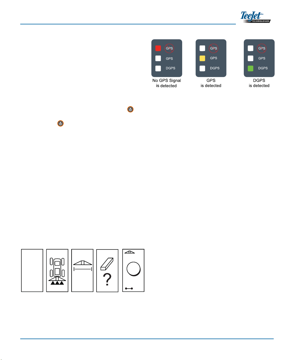
GPS detected
Operation
Screen
+0
29.
Swath Width
Screen
5
BP
TeeJet
© 2008
Copyright
Software
Version Screen
CL230
Splash Screen
6 KM/ H
Area Reset
Screen
V1.07
If the DGPS light is blinking, communication has been
established with the GPS source; however, NMEA out-
put rate is too slow. Ensure proper NMEA message set-
tings of 5 Hz GGA in the GPS device. Application cannot
occur until proper communication is established.
A
A
CENTERLINE
230BP

Setup6
5
3 0
Area Reset
At the end of the CL230BP power up sequence, the
Area Reset window will be displayed:
Area Reset retains existing bounded
and applied areas and A-B guide-
lines. This option allows the bounded
and applied areas and guidelines to
be reset before starting on a new
field or continuing an existing field.
To reset the bounded and applied ar-
eas and guidelines, press the Enter
key. If the previous application is
being resumed, press the Escape
key to continue to Operation or Setup
mode. This screen is only available
upon CL230BP power up. It cannot
be accessed during normal opera-
tion.
Setup Mode
Press the Setup Mode key to enter into CL230BP
Setup Mode. The initial CL230BP Setup Mode Screen
will be displayed.
Press the Enter• key to save the setting and
advance the screen.
Press the Escape• key to exit from Setup Mode
without saving any changes.
After 10 seconds of inactivity, Setup Screens will•
time out (changes will be saved). The CL230BP
will return to Operation Mode.
INITIAL SETUP SCREEN
This is the initial CL230BP Setup
Screen. Press the Enter key to
advance to the Boom Width screen.
Setup screens will time out after 10
seconds of inactivity (changes will be
saved). After time out, the screen will
go back to Operation Mode. Press
the Escape key to exit from Setup
Mode without saving any changes.
BOOM WIDTH
Encode the total width of the boom.
Use the Plus and Minus keys
to adjust the value. The boom sec-
tion width range is 0 cm to 50 m (0
to 1969 inches). The minimum rec-
ommended width is 1 m (39 inches).
Press the Enter key to accept the
changes to the last boom section and
advance to the Boom Offset Direction
setting.
BOOM OFFSET DIRECTION
A BACKWARD selection (as shown)
indicates the boom is located be-
hind the GPS antenna as the vehicle
moves in a forward direction. A FOR-
WARD selection indicates the boom
is located in front of the GPS antenna
as the vehicle moves in a forward di-
rection. Use the Plus and Minus
keys to adjust between Forward or
Backward. Press the Enter key to
accept the changes and advance to
the Boom Offset Distance setting.
6

CenterLine 230BP
020-020-UK R0
7
Display Setup Mode
Press the Setup Mode key until the initial Display
Setup Mode screen appears.
DISPLAY SETUP SCREEN
Thisis theinitial DisplaySetup Screen.
Setup screens will time out after 10
seconds of inactivity (changes will be
saved). After time out, the screen will
go back to Operation Mode. Pressing
the Escape key will also exit the
user from Setup Mode without saving
any changes. Press the Enter key
to advance to the Display Brightness
setting.
DISPLAY BRIGHTNESS
The Plus and Minus keys can
be used to change the brightness lev-
els of the display screen. Press the
keys until the desired brightness is
established. Press the Enter key
to advance to the Display Contrast
setting.
DISPLAY CONTRAST
The Plus and Minus keys can
be used to change the contrast levels
of the display’s background. Press
the Enter key to advance to the
Display Background setting.
NOTE: The Plus and Minus keys control
console brightness levels during Opera-
tions modes. However, if GPS signal is
not being received, the Plus and Minus
keys will control the contrast level.
BOOM OFFSET DISTANCE
Define the distance from the GPS
antenna to the boom in decimal feet
(decimal meters). The boom offset
distance range is 0 to 50 meters (0
to 164 decimal feet). Use the Plus
and Minus keys to change the
value. Press the Enter key to ac-
cept the changes.
Once the final setting has been entered and saved,
the screen will return to the initial CL230BP Setup
Screen. If no additional changes are required, press
the Escape key to exit to Operation Mode.
7
3 0
19.5
Setup8
DISPLAY BACKGROUND
The Plus and Minus keys toggle
between light and dark backgrounds.
Press the keys until the desired back-
ground is established. Press the En-
ter key to accept the changes.
LED SPACING
The distance illustrated by the illumi-
nated LEDs can be customized. The
default setting is 30 cm (1 ft). Use the
Plus and Minus keys to adjust
the spacing as required for individual
preference. Press the Enter key to
accept the changes.
COM PORT SETUP
The COM Port can be customized to
send DGPS data out or accept exter-
nal DGPS. “0” means the console is
accepting external DGPS data. “1”
means the console is using internal
DGPS and is transmitting out. Use
the Plus and Minus keys to
toggle the COM Port number. Press
the Enter key to accept the chan-
ges.
NOTE: Power must be cycled to the console if
this setting is changed.
GPS SETUP
GPS Setup can be customized
to accept “ANY” available source
transmission (either uncorrected or
differential), “GPS” source transmis-
sions (only uncorrected signals), or
“DGPS” source transmissions (only
differentially corrected signals). Use
the Plus key to select “ANY,”
“GPS,” or “DGPS” and the Minus
key to revert backward. Press the
Enter key to accept the changes.
NOTE: Power must be cycled to the console if
this setting is changed.
Once the final setting has been entered, the screen
will return to the initial Display Setup Mode screen. If
no additional changes are required, press the Escape
key and exit to Operation Mode or press the Set-
up Mode key again to enter into CL230BP Setup
Mode.
ANY
CenterLine 230BP
020-020-UK R0
9
CHAPTER 3 - OPERATION
Power Up Sequence
Power up the system by pressing the Power
button.
Power down the system by pressing and holding the
Power button approximately four (4) seconds.
At power up, the CL230BP will perform the following
steps:
Display copyright and software version screen
•
for three (3) seconds.
Display the splash screen for two (2) seconds.
•
Detect if GPS data are present (this occurs simul-•
taneously within the display screen sequence).
Display the current swath width for three (3) sec-
•
onds.
The Area Reset screen will be displayed.
•
The splash screen is displayed until the DGPS•
LED is illuminated or Setup mode is entered.
Once DGPS is locked, the Operation screen will
be displayed.
CL230BP Operation Reference
Screens
Navigation Screen - Mark A-B
29.
Swath Width
Screen
5
BP
TeeJet
© 2008
Copyright
Software
Version Screen
CL230
Splash Screen GPS detected
Operation
Screen
+0
Area Reset
Screen
V1.07
+0
6.0 MPH
Swath Number
+ to the right of the A-B baseline
- to the left of the A-B baseline
Return to Point Indicator
indicates a point is stored
Guidance Mode
Straight A-B Guidance
Curved A-B Guidance
Circle Pivot Guidance
Headland Circuit
Action Indicator (currently
Mark Point A)
Vehicle Speed
If the DGPS light is flashing, communication has been
established with the GPS source; however, NMEA out-
put rate is too slow. Ensure proper NMEA message set-
tings of 5 GGA in the GPS device. Application cannot
occur until proper communication is established.
6 km/h
6 km/h
CENTERLINE
230BP
Operation10
Navigation Screen - Operation
Guidance Screen - Map Page
Bounded Area Screen
NOTE: If a SmartCable is not connected to the
system, the console cannot be placed in
“Auto” mode. However, acreage can be
bounded.
6.0 MPH
1.5
Swath Number
+ to the right of the A-B baseline
- to the left of the A-B baseline
Guidance Mode
Straight A-B Guidance
Curved A-B Guidance
Circle Pivot Guidance
Headland Circuit
Distance to main guideline
Vehicle Speed
Direction to main guideline
+1
6.0 Ft
Center guideline
Next guideline to the right
Next guideline to the left
Distance from
center guideline
M
1435.00
Bounded Area
Indicates a bounded area has been
completed
Hectares (acres) Bounded
Indicates the number of hectares
bounded by Headland Circuit
55
6 km/h

CenterLine 230BP
020-020-UK R0
11
Operation Function Keys
There are several functions that can be performed
during operation. Most of these functions are initiated
by the four arrow keys, located on the keypad.
NOTE: The Plus and Minus keys control
console brightness levels during Opera-
tions modes. However, if GPS is not be-
ing received, the Plus and Minus
keys will control the contrast level.
Operations Screens
Several screens are displayed during vehicle opera-
tion. They are consistent throughout the application
and appear as follows.
To change the view of any screen during Operations
mode, press the Change Page key.
Guidance Operation - Modes
Guidance capabilities include Straight A-B, Curved
A-B, Circle Pivot, and Headland Circuit.
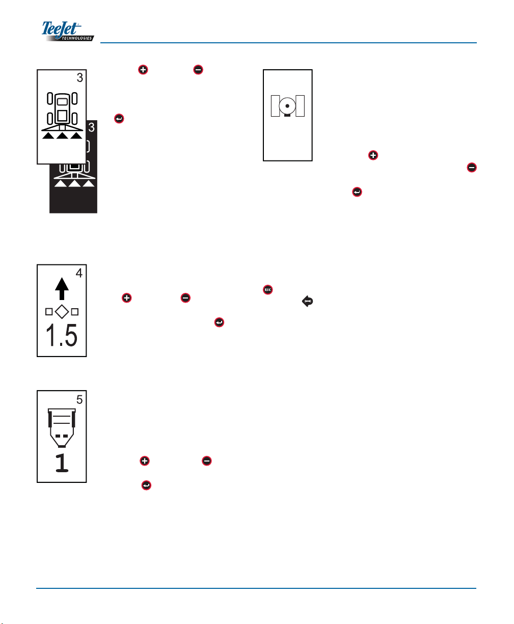
Headland Circuit Guidance
Headland Circuit guidance is used to establish a pe-
rimeter around the application area. The CL230BP
will collect and store bounded area once the Head-
land Circuit is closed. The CL230BP will allow two
passes around the perimeter of the field - the original
perimeter pass and one additional pass. Guidance is
applied during the second pass, after the first pass
has been completed.
NOTE: Booms will not operate outside of the
bounded area once it is established.
1. Use the Guidance Mode key to select Head-
land Circuit guidance.
2. Drive to the desired headland location of Point
A. With the vehicle in motion, press the Mark A/B
key to establish Point A. Drive around the
perimeter of the field. The CL230BP will auto-
lights illuminated on the right of the
lightbar require a steering adjust-
ment to the left
lights illuminated on the left of the
lightbar require a steering adjust-
ment to the right
Center
60 cm (2 ft)
90 cm (3 ft)
1.2 m (4 ft)
1.5 m (5 ft)
30 cm (1 ft)
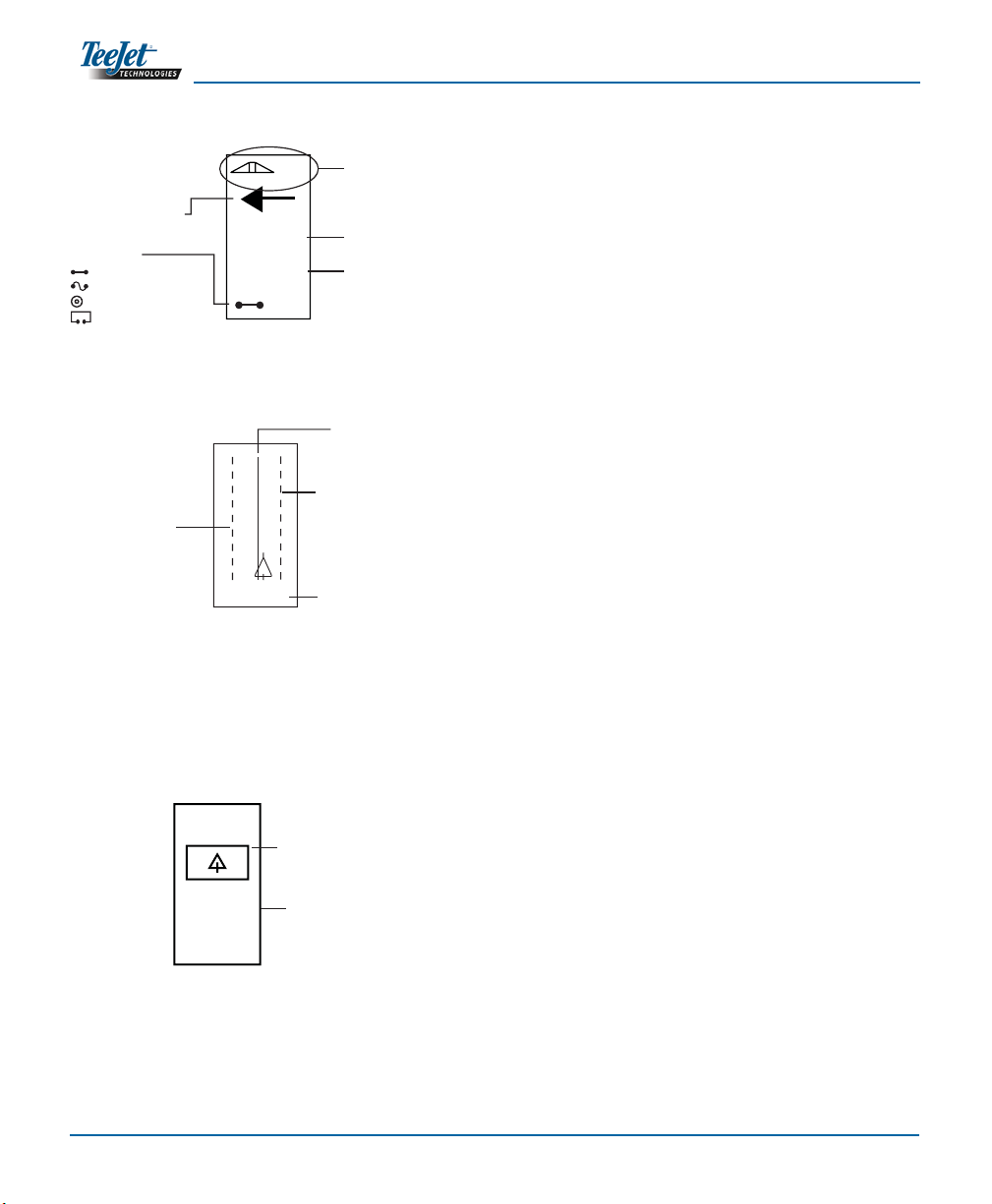
Guidance Mode
This key selects the desired guidance
mode:
Straight A-B Guidance
Curved A-B Guidance
Circle Pivot Guidance
Headland Circuit
Setup Mode
This key exits OPERATION
and enters SETUP mode.
Mark A-B Line
This key allows the operator to estab-
lish a new A-B line. Return to Point
This key allows the operator to estab-
lish a point in memory so CL230BP
can navigate the vehicle back to that
point.
+2
6.0 MP
1.5
Navigation
Screen
H
6.0 Ft
Map Page Completed Circuit -
Calculated Area
KM/H
M
55
Operation12
Establish
Point A
Establish
Point B
+0
6.0 MPH
+0
6.0 MPH
+0
6.0 MPH
0.0
Navigation
Screen
A
B
matically close the boundary when the vehicle
is within one boom width of Point A. The Com-
pleted Circuit (hourglass) will be briefly displayed
as the perimeter is closed.
Guidance Points A and B can be established at
any time during Headland Circuit mode. These
points can be used as reference for Straight or
Curved A-B guidance (used during interior ap-
plication). To mark Points A and B, press the
Guidance Mode key to select either Straight,
or Curved A-B mode and mark the points at the
desired locations using the Mark A/B key. The
points will be stored for future reference.
The CL230BP will provide navigation information
to complete a second headland circuit pass. If
Guidance Points A and B were not marked dur-
ing Headland Circuit, select a new Guidance
Mode and establish an A-B line to complete the
interior application.
3. Use the Change Page key to advance the
screen views as illustrated above.
Straight A-B Guidance
Straight A-B guidance provides straight line guidance
based on a reference (A-B) line. The original A-B line
is used to calculate all other parallel guidelines.
1. Use the Guidance Mode key to select Straight
A-B guidance.
2. Drive to the desired location of Point A. While the
vehicle is in motion, press the Mark A/B key
to establish Point A. Point B will be displayed on
the screen. Drive to the location of Point B and
press the Mark A/B key again to establish the
A-B line. The CL230BP will immediately begin
providing navigation information with the lightbar
and Navigation Screen.
3. Use the Change Page key to advance the
screen views.
Curved A-B Guidance
Curved A-B Guidance is similar to Straight A-B Guid-
ance except that the reference line is curved.
NOTE: Curved Guidance is recommended not to
exceed 300within the A-B guideline.
1. Use the Guidance Mode key to select Curved
A-B guidance.
2. Drive to the desired location of Point A. While the
vehicle is in motion, press the Mark A/B key
to establish Point A. Point B will be displayed on
the screen. Drive to the location of Point B and
press the Mark A/B key again to establish the
km/h
A
B
km/h km/h
CenterLine 230BP
020-020-UK R0
13
3. Use the Change Page key to advance the
screen views.
Compass View/Return to Point
Press the Return to Point key to
establish a point in memory. Normal
guidance will continue uninterrupted
during this process.
To navigate back to the established
point, press the Return to Point
key again. The Compass View
screen will be displayed and will pro-
vide navigation assistance to return
to the established point.
Push the Return to Point key a
third time to erase the stored point
and return to the navigation screens.
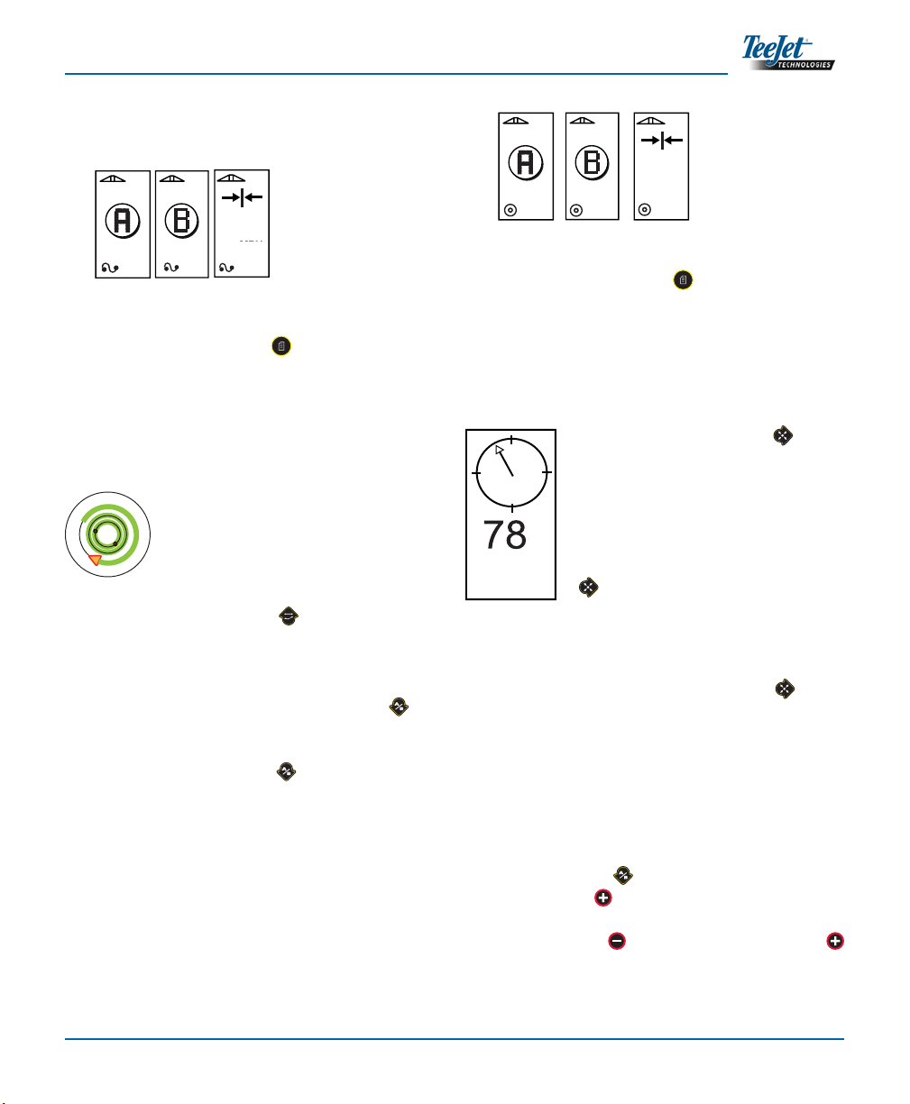
A+ Nudge Feature
The A+ Nudge feature allows the existing A-B guide-
line to be shifted to the vehicle’s current location.
Press the Mark A/B key immediately followed by
pressing the Plus key.
Pressing the Minus key after pressing the Plus
key will abort the nudge feature and the guideline will
remain the same.
A-B line. The CL230BP will immediately begin
providing navigation information with the light-
bar and Navigation Screen.
3. Use the Change Page key to advance the
screen views.
Circle Pivot Guidance
Circle Pivot guidance provides guidance around a
central location that radiates outward.
1. Use the Guidance Mode key to select Circle
Pivot guidance.
2. Drive to the desired location of Point A. With the
vehicle in motion, press the Mark A/B key
to establish Point A. Point B will be displayed
on the screen. Drive to the location of Point B
and press the Mark A/B key again to estab-
lish the A-B line. Point B must be at least 1/2 of
the way around the circle to complete the circle
pivot. Once Point B has been established, the
CL230BP will immediately begin providing navi-
gation information with the lightbar and Naviga-
tion Screens.
Establish
Point A
+0
6.0 MP
+0
6.0 MPH
Establish
Point B
H
+0
6.0 MPH
0.0
Navigation
Screen
km/h
+0
6.0 MPH
Establish
Point A
Establish
Point B
+0
6.0 MPH
+0
6.0 MPH
0.0
Navigation
Screen
A
B
km/h km/h
6.0 MPH
km/h km/h km/h
M
km/h

Operation14
Other manuals for Centerline 230BP
1
Table of contents
Other TeeJet Technologies Car Navigation System manuals


Popular Car Navigation System manuals by other brands


Magellan
Magellan RoadMate 6000T - Automotive GPS Receiver Manual de referencia

Pioneer
Pioneer AVIC-F840BT installation manual

Clarion
Clarion NAX980HD owner's manual

Sanyo
Sanyo NV-E7000 - Portable GPS And Mobile DVD Entertainment... Service manual

JRC
JRC JAN-901B - brochure

VDO
VDO PN 2050 - quick start guide


