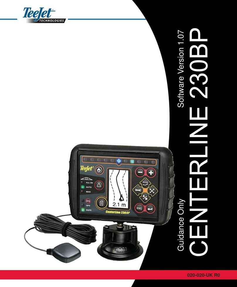
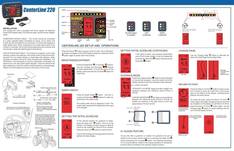
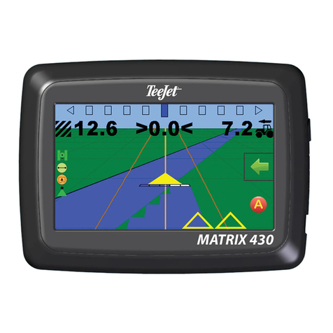
TeeJet Technologies MATRIX PRO940gs User manual

MATRIX®PROGS
ASSISTED/AUTO STEERING
SETUP GUIDE
TeeJet Technologies
1801 Business Park Drive
Springeld, Illinois 62703 USA
www.teejet.com
For use with software version 3.0x
98-05242-ENUS R4 English-US
© TeeJet Technologies 2013

Copyrights
© 2013 TeeJet Technologies. All rights reserved. No part of this document or the computer programs described in it may be reproduced, copied,
photocopied, translated, or reduced in any form or by any means, electronic or machine readable, recording or otherwise, without prior written
consent from TeeJet Technologies.
Trademarks
Unless otherwise noted, all other brand or product names are trademarks or registered trademarks of their respective companies or organizations.
Limitation of Liability
TEEJET TECHNOLOGIES PROVIDES THIS MATERIAL “AS IS” WITHOUT WARRANTY OF ANY KIND, EITHER EXPRESSED OR IMPLIED.
NO COPYRIGHT LIABILITY OR PATENT IS ASSUMED. IN NO EVENT SHALL TEEJET TECHNOLOGIES BE LIABLE FOR ANY LOSS OF
BUSINESS, LOSS OF PROFIT, LOSS OF USE OR DATA, INTERRUPTION OF BUSINESS, OR FOR INDIRECT, SPECIAL, INCIDENTAL, OR
CONSEQUENTIAL DAMAGES OF ANY KIND, EVEN IF TEEJET TECHNOLOGIES HAS BEEN ADVISED OF SUCH DAMAGES ARISING FROM
TEEJET TECHNOLOGIES SOFTWARE.
Safety Information
TeeJet Technologies is not responsible for damage or physical harm caused by failure to adhere to the following safety requirements.
As the operator of the vehicle, you are responsible for its safe operation.
Assisted/Auto Steering is not designed to replace the vehicle’s operator.
Do not leave a vehicle while the Assisted/Auto Steering is engaged.
Be sure that the area around the vehicle is clear of people and obstacles before and during engagement.
The Assisted/Auto Steering is designed to support and improve efciency while working in the eld. The driver has full responsibility for the quality
and work related results.
Disengage Assisted/Auto Steering before operating on public roads or when not in use to prevent loss of vehicle control.
WARNING: PINCH POINT HAZARD! To prevent serious injury or death, avoid unsafe practice while manually operating hydraulic
steering circuits. Keep others away and stay clear of mechanical steering linkages.

1
98-05242-ENUS R4
Matrix®Pro GS
Table of Contents
GENERAL MATRIX®PRO INFORMATION 2
Unavailable Options When Job is Active ....................................................................................................................2
Warnings and Information Pop-ups ............................................................................................................................2
Drop Down Menu Selections .....................................................................................................................................2
Scrolling Screens ......................................................................................................................................................2
Setup Option Information...........................................................................................................................................3
Keyboard Entry Screen .............................................................................................................................................3
Unit Setup Mode Availability ............................................................................................................................................3
GPS is Required .......................................................................................................................................................4
PRN Not Shown...............................................................................................................................................................4
ASSISTED/AUTO STEERING CONFIGURATION 5
AUTOSTEER 6
Assisted/Auto Steering Unavailable.................................................................................................................................6
Enable/Disable Assisted/Auto Steering..................................................................................................................................................6
Valve Setup .......................................................................................................................................................................................................7
Valve Type ...............................................................................................................................................................7
Valve Frequency .......................................................................................................................................................7
Minimum/Maximum Duty Cycle Tests ........................................................................................................................8
Minimum Duty Cycle Left Test .........................................................................................................................................8
Minimum Duty Cycle Right Test.......................................................................................................................................9
Maximum Duty Cycle Test ...............................................................................................................................................9
Steering Settings ......................................................................................................................................................................................... 10
Coarse Steering Adjustment ...................................................................................................................................11
Fine Steering Adjustment ........................................................................................................................................11
Deadband ...............................................................................................................................................................12
Lookahead ..............................................................................................................................................................12
Valve Test ....................................................................................................................................................................................................... 13
Valve Diagnostics......................................................................................................................................................................................... 13
Steering Valve – No Master Solenoid ............................................................................................................................14
Steering Valve – With Master Solenoid..........................................................................................................................14
Options: Steering Wheel Sensor............................................................................................................................................................. 15
Steering Angle Sensor ............................................................................................................................................................................... 15
Enable/Disable Steering Angle Sensor ...................................................................................................................16
Sensor Calibration ...................................................................................................................................................16
On Line Calibration ................................................................................................................................................17
TILT CORRECTION 18
Field Level Unavailable..................................................................................................................................................18
Tilt Correction Unavailable.............................................................................................................................................18
Enable/Disable Tilt ...................................................................................................................................................................................... 18
Field Level ..............................................................................................................................................................19
AUTO/ASSISTED STEERING OPERATION 20
APPENDIX FACTORY SETTINGS & RANGES 21

2www.teejet.com
Assisted/Auto Steering
GENERAL MATRIX®PRO INFORMATION
The Matrix Pro GS is used to congure the vehicle and its implements including assisted/auto steering and tilt correction.
Unavailable Options When Job is Active
When a job is active some setup options are unavailable. See the Unit
Setup Mode Availability Chart for indication of which options are not
accessible.
Figure GS-1: Example of Unavailable Options
Warnings and Information Pop-ups
A pop-up warning or information box will be displayed for approximately
ve (5) seconds. To remove the information box, tap anywhere on the
screen.
Figure GS-2: Information screens
Dimming backlight brightness to
reduce heat. Previous backlight
brightness will be restored when
unit reaches a safe temperature.
Overheat Protection
Drop Down Menu Selections
Press DOWN arrow to access the options. Use the UP/DOWN
arrows or slide bar if necessary to scroll through the extended
list. Select the appropriate option. To close the list without selecting an
option, tap anywhere on the screen outside the drop down menu.
Figure GS-3: Example of Drop Down Menu
Backward
Forward
Scrolling Screens
Some screens have more information or options that are visible beyond
the current screen. Use the UP/DOWN arrows or slide bar to
access additional options or information not currently visible on the
screen.
Figure GS-4: Example of Scrolling Screen

3
98-05242-ENUS R4
Matrix®Pro GS
Setup Option Information
Press the option’s icon or option’s name of any menu item to display a
denition and range values of that item. To remove the information box,
press anywhere on the screen.
Figure GS-5: Example of Information Text Box
Keyboard Entry Screen
Press the KEYPAD icon . Use the numeric keypad to enter a
value.
Press the ACCEPT icon to save the settings or the CANCEL
icon to leave the keypad without saving.
Figure GS-6: Example of Keyboard
Antenna to Boom (ft)
1 2 3
14.50
Clear
4 5 6 <--
7 8 9
0 . +/-
Unit Setup Mode Availability
Conguration
Implement
–
Machine Type
GPS Antenna Height
Implement Type
Symmetric Implement Layout
Implement Offset Distance
Implement Offset Direction
Number of Implement Sections
Guidance Width
Application/Working Width
Applied Area Alarm
–
Straight
Mode
Boom Offset Direction
Antenna to Boom Distance
Overlap
Delay On/Off Times
Spreader
Mode
Setup Type: TeeJet
• Antenna to Disks Distance
• Overlap
• Delay On/Off Times
• Spread Offset Distance
• Section Offsets
• Section Lengths
Setup Type: OEM
• Antenna to Disks Distance
• Start/Stop Distance
• Section Start/Stop Offsets
Staggered
Mode
Section 1 Offset Direction
Antenna to Section 1
Overlap
Delay On/Off Times
Section Offsets
AutoSteer
–Enabled/Disabled
–Valve
Setup
Valve Type
Valve Frequency
Minimum Duty Cycle Left/ Right
Maximum Duty Cycle
–Steering
Settings
Coarse Steering Adjustment
Fine Steering Adjustment
Deadband
Lookahead
–Valve Test
–Valve Diagnostics
–Options Steering Wheel Sensor
–
Steering
Angle
Sensor
Enable
Sensor Calibration
On Line Calibration
Tilt
Correction –Enabled/Disabled
Field Level
GPS –
GPS Type
GPS Port
GPS Status Information
Program Receiver
PRN
Available during an active job
Not Available during an active job

4www.teejet.com
Assisted/Auto Steering
GPS is Required
GPS is used to congure GPS Type, GPS Port and PRN as well as to
view GPS status information. For detailed setup instructions, refer to
the GPS chapter in the Matrix Pro GS user manual.
NOTE: These settings are required for assisted/auto steering and tilt
sensor operation, as well as proper implement operation.
1. Press CONFIGURATION side tab .
2. Press GPS .
3. Select from:
►GPS Type – select GPS source transmissions
►GPS Port – sets (D)GPS communication port
►GPS Status – displays information regarding GGA/VTG (Data
Rates), Number of Satellites, HDOP, PRN, GGA Quality, GPS
Receiver, Receiver Version and UTM Zone
►Program – allows direct programming of the GPS receiver
through a command line interface
►PRN – selects the SBAS PRN that will provide GNSS differential
correction data. Set to Automatic for automatic PRN selection.
►Alternate PRN – when PRN is not automatic, a second alternate
SBAS PRN will provide a second set of GNSS differential
correction data.
4. Press RETURN arrow or CONFIGURATION side tab to
return to the main Conguration screen.
Figure GS-7: GPS
PRN Not Shown
When GPS Type is set to “GPS+GLONASS”, PRN options are not
available, nor shown on screen.

5
98-05242-ENUS R4
Matrix®Pro GS
ASSISTED/AUTO STEERING CONFIGURATION
The Matrix Pro GS is used to congure the vehicle and its implements
including assisted/auto steering and tilt. For recommendations and
factory settings for the FieldPilot or UniPilot setup values, see chart on
page 21.
To access Matrix Pro GS AutoSteer and Tilt conguration options:
1. Press UNIT SETUP bottom tab .
2. Press CONFIGURATION side tab .
3. Select from:
►AutoSteer – used to enable/disable assisted/auto steering as
well as establish valve setup settings, steering settings and
steering angle sensor settings; and perform valve tests, or valve
diagnostics
►Tilt Correction – used to enable/disable and calibrate the tilt
gyro module, allowing for tilt correction for application on hilly or
sloped terrain
Figure GS-8: Configuration Options - AutoSteer
Figure GS-9: Configuration Options - Tilt Correction

6www.teejet.com
Assisted/Auto Steering
AUTOSTEER
When a Steering Control Module (SCM) is present, Assisted/Auto
Steering options will be available
NOTE: An update of your SCM software may be required when
upgrading to a Matrix Pro GS from previous Matrix
systems. To view version of software information, see the
Console->About screen.
AutoSteer setup is used to Enable/Disable Assisted/Auto Steering and
congure Valve Setup, Steering Settings, Valve Test, Valve Diagnostics
and Steering Angle Sensor. For recommendations and factory settings
for the FieldPilot or UniPilot setup values, see chart on page 21.
1. Press CONFIGURATION side tab .
2. Press AutoSteer .
3. Select if assisted/auto steering is enabled or disabled.
4. When enabled, select from:
►Valve Setup – used to congure Valve Type, Valve Frequency,
Minimum Duty Cycle Left/Right and Maximum Duty Cycle
►Steering Settings – used to establish Coarse Steering
Adjustment, Fine Steering Adjustment, Deadband and
Lookahead
►Valve Test – used to verify if steering is directed correctly
►Valve Diagnostics – used to test the valves to see if they are
connected properly
►Options: Steering Wheel Sensor – used to select whether the
steering disengage sensor is magnetic or pressure sensor based
►Steering Angle Sensor – used to establish and calibrate the
Steering Angle Sensor (SAS) as the primary feedback sensor for
auto steering.
5. Press RETURN arrow or CONFIGURATION side tab to
return to the main Conguration screen.
Figure GS-10: AutoSteer
Assisted/Auto Steering Unavailable
If a assisted/auto steering system is not installed, setup options will not
be available.
Figure GS-11: Assisted/Auto Steering Not Detected
Enable/Disable Assisted/Auto Steering
Set assisted/auto steering to Enable or Disable.
1. Press DOWN arrow to access the list of options.
2. Select:
►Enable
►Disabled
If disabled, all Assisted/Auto Steering capabilities and setup functions
will be unavailable (options will be grayed out).
Figure GS-12: Enabled and Disabled Assisted/Auto Steering Options

7
98-05242-ENUS R4
Matrix®Pro GS
Valve Setup
Valve Setup is used to congure Valve Type, Valve Frequency,
Minimum Duty Cycle Left, Minimum Duty Cycle Right and Maximum
Duty Cycle. For recommendations and factory settings for the FieldPilot
or UniPilot setup values, see chart on page 21.
1. Select Valve Setup .
2. Select from:
►Valve Type– used to select the type of steering valve
►Frequency – used to select the valve frequency used to drive the
steering valve
►Minimum Duty Cycle Left and Right – used to set the minimum
amount of drive required to begin steering the vehicle left or right
►Maximum Duty Cycle – used to select the maximum speed that
the wheels will steer from lock to lock
Figure GS-13: Valve Setup
Valve Type
Valve type is used to set the type of steering valve. For
recommendations and factory settings for the FieldPilot or UniPilot
setup values, see chart on page 21.
1. Press DOWN arrow to access the list of options.
2. Select type.
Figure GS-14: Valve Type
Standard/PWM
Standard Voltage
Reverse Voltage
One-Wire PWM
UniPilot
Valve Frequency
Valve frequency is used to drive the steering valve. The type of valve
being used determines the frequency. Range is 0.9 - 15000.1. For
recommendations and factory settings for the FieldPilot or UniPilot
setup values, see chart on page 21.
1. Press the KEYPAD icon .
2. Use the entry screen to establish the valve frequency.
Figure GS-15: Valve Frequency
Valve Frequency
1 2 3
175
Clear
4 5 6 <--
7 8 9
0 . +/-

8www.teejet.com
Assisted/Auto Steering
Minimum/Maximum Duty Cycle Tests
Minimum Duty Cycle (Minimum DC Left + Right) sets the minimum
amount of drive required to begin steering the vehicle left or right.
Range is 0.0 - 50.0. Default is 20%.
Maximum Duty Cycle sets the maximum speed that the wheels will
steer from left to right / right to left (lock to lock). Range is 25 - 100.
Default is 50%.
NOTE: A GPS signal is required for these tests.
RECOMMENDATION: Have a large area of clear space available to
perform test cycles. Vehicle speed must be between 1.0 mph
and 8.0 mph / 1.5 - 13.0 km/h (0.4 - 3.6 m/s).
WARNING: Pinch Point Hazard!
To prevent serious injury or death, avoid unsafe practice while
manually operating hydraulic steering circuits. Keep others
away and stay clear of mechanical linkage.
Figure GS-16: Duty Cycle Tests
Minimum Duty Cycle Left Test
Minimum Duty Cycle Left sets the minimum amount of drive required to
begin steering the vehicle to the left.
NOTE: If the valve frequency is set below 15 Hz (non proportional), set
the amount of drive to “25.0”. Cycle test is not necessary.
1. Press the KEYPAD icon .
2. While the vehicle is moving in a slow forward straight line motion
between 1.0 mph and 8.0 mph / 1.5 - 13.0 km/h (0.4 - 3.6 m/s),
press Test Left .
3. Press the engage/disengage switch or foot switch to activate the
test.
4. Slowly increase the duty cycle number using the UP arrow until
the vehicle begins to turn left.
5. Turn the steering wheel or press the engage/disengage switch or
foot switch to complete the test.
Figure GS-17: Minimum Duty Cycle Test

9
98-05242-ENUS R4
Matrix®Pro GS
Minimum Duty Cycle Right Test
Minimum Duty Cycle Right sets the minimum amount of drive required
to begin steering the vehicle to the right.
NOTE: If the valve frequency is set below 15 Hz (non proportional), set
the amount of drive to “25.0”. Cycle test is not necessary.
1. Press the KEYPAD icon .
2. While the vehicle is moving in a slow forward straight line motion
between 1.0 mph and 8.0 mph / 1.5 - 13.0 km/h (0.4 - 3.6 m/s),
press Test Right .
3. Press the engage/disengage switch or foot switch to activate the
test.
4. Slowly increase the duty cycle number using the UP arrow until
the vehicle begins to turn right.
5. Turn the steering wheel or press the engage/disengage switch or
foot switch to complete the test.
Figure GS-18: Minimum Duty Cycle Test
Maximum Duty Cycle Test
Maximum Duty Cycle sets the maximum speed that the wheels will
steer from lock to lock. For recommendations and factory settings for
the FieldPilot or UniPilot setup values, see chart on page 21.
NOTE: If the valve frequency is below 15 Hz (non proportional), set the
value to 100. Speed will be established during the Valve Test.
1. Press the KEYPAD icon .
2. While the vehicle is moving in a slow forward motion between 1.0
mph and 8.0 mph / 1.5 - 13.0 km/h (0.4 - 3.6 m/s), turn the wheels
all the way to the left (or right).
3. Press the RIGHT arrow (or LEFT arrow ).
4. Press the engage/disengage switch or foot switch to activate the
test. This will start a timer as well as turn the vehicle to the right (or
left).
WARNING! When using a UniPilot, the UniPilot will move the
steering wheel very quickly. Keep loose clothing, hair and
hands away from the steering wheel while preforming this test.
5. When the wheels are all the way to the right (or left), stop the test
by pressing the engage/disengage switch or foot switch. The time
displayed is the lock to lock time.
6. Repeat to perform procedure to the opposite side.
7. Compare the lock-to-lock time with the recommended time.
8. Press the UP/DOWN arrows to adjust the value.
►Lock-to-lock time is too low (turning too fast) – decrease the
value
►Lock to lock time is higher (turning too slow) – increase the value
9. Repeat until recommended lock time is achieved.

10 www.teejet.com
Assisted/Auto Steering
Figure GS-19: Maximum Duty Cycle Steering Settings
Steering Settings is used to congure Coarse Steering Adjustment,
Fine Steering Adjustment, Deadband and Lookahead settings.
1. Select Steering Settings .
2. Select from:
►Coarse Adjustment – used to select how aggressively the
vehicle maintains a guideline in Straight AB Guidance
►Fine Adjustment – used to select how aggressively the vehicle
maintains a guideline in Curved AB Guidance
►Deadband – used to set if steering is too choppy/responsive or
remains consistently off the guideline
►Lookahead – used to select the vehicle’s approach to the
guideline in Straight AB Guidance mode
Figure GS-20: Steering Settings

11
98-05242-ENUS R4
Matrix®Pro GS
Coarse Steering Adjustment
Coarse Steering Adjustment adjusts how aggressively the
vehicle maintains a guideline in Straight AB Guidance mode.
Range is 0.0 - 100.0. Default is 25.0.
1. Press:
►UP arrow if the vehicle is drifting away from the guideline or
not approaching it fast enough.
►DOWN arrow if the vehicle is oscillating rapidly or
overshooting the guideline.
Figure GS-21: Coarse Steering Adjustment
Fine Steering Adjustment
Fine Steering Adjustment adjusts how aggressively the vehicle
maintains a guideline in Curved AB Guidance mode. Range is 0.0 -
100.0. Default is 25.0.
1. Press:
►UP arrow if the vehicle drives outside of corners.
►DOWN arrow if the vehicle cuts corners.
Figure GS-22: Fine Steering Adjustment

12 www.teejet.com
Assisted/Auto Steering
Deadband
Deadband adjusts if steering is too choppy/responsive or remains
consistently off the guideline. As the value is increased, stability will
increase but so will steady state error. Range is 1 - 10. Default is 1.
1. Press:
►UP arrow if steering is too choppy or too responsive.
►DOWN arrow if the vehicle remains consistently off the
guideline.
Figure GS-23: Deadband
Lookahead
Lookahead used during Straight AB Guidance mode to
adjust the vehicle’s approach to the guideline. Fine tune the
Lookahead by conducting several approaches to the guideline.
Range is 0.0 - 10.0 seconds. Default is 4.0 seconds.
1. Press:
►UP arrow if the vehicle is overshooting the guideline when
approaching.
►DOWN arrow if the vehicle takes too long to get to the
guideline.
Figure GS-24: Lookahead

13
98-05242-ENUS R4
Matrix®Pro GS
Valve Test
The Valve Test veries if steering is directed correctly. It can also be
used to test the amount of time to steer the wheels from full left to full
right (lock to lock) for non-proportional valves.
For non-proportional valves, the amount of time for left-to-right or right-
to-left (lock to lock) will be established by mechanically adjusting oil
ow through the valve.
For a UniPilot ESM, the amount of time for left-to-right or right-to-left
(lock to lock) will be established by adjusting the Max Duty Cycle value.
For recommendations and factory settings for the FieldPilot or UniPilot
setup values, see chart on page 21.
1. Select Valve Test .
2. While the vehicle is moving in a slow forward motion, turn
the wheels all the way to the left.
3. Press RIGHT arrow .
4. Press the engage/disengage switch or foot switch to activate the
test. This will start a timer as well as turn the vehicle to the right.
WARNING! When using a UniPilot, the UniPilot will move the
steering wheel very quickly. Keep loose clothing, hair and
hands away from the steering wheel while preforming this test.
5. Press the engage/disengage switch or foot switch when the wheels
are all the way to the right. The time displayed is the lock to lock
time.
6. While the vehicle is moving in a slow forward motion, turn
the wheels all the way to the right.
7. Press LEFT arrow .
8. Press the engage/disengage switch or foot switch to activate the
test. This will start a timer as well as turn the vehicle to the left.
WARNING! When using a UniPilot, the UniPilot will move the
steering wheel very quickly. Keep loose clothing, hair and
hands away from the steering wheel while preforming this test.
9. Press the engage/disengage switch or foot switch when the wheels
are all the way to the right. The time displayed is the lock to lock
time.
10. Compare the lock-to-lock time with the recommended time.
11. Adjust the valve oil ow as needed and repeat test as needed.
Figure GS-25: Valve Test
Valve Diagnostics
The valve diagnostic test veries if the valve is operating correctly.
This test is not necessary for UniPilot.
NOTE: The diagnostic tests do not require that the vehicle is in motion.
A valid GPS signal is not required.
Figure GS-26: Valve Diagnostics

14 www.teejet.com
Assisted/Auto Steering
Steering Valve – No Master Solenoid
1. Select Valve Diagnostics .
2. Activate the Left or Right check boxes associated with the valve direction to be tested.
3. Press and hold the engage/disengage switch or foot switch for one second.
NOTE: Do not activate the Master check box.
Test Reactions
Selected
Reaction Issue
Left Master Right
None Valve is operating correctly
Wheels turn Either the left valve or right valve is stuck open
● Vehicle turns left Valve is operating correctly
● None SCM, harness or valve malfunction
● Vehicle turns right Left and right connections to valve are reversed
● Vehicle turns right Valve is operating correctly
● None SCM, harness or valve malfunction
● Vehicle turns left Left and right connections to valve are reversed
Steering Valve – With Master Solenoid
1. Select Valve Diagnostics .
2. Activate the Master check box.
3. Activate the Left or Right check boxes associated with the valve direction to be tested.
4. Press and hold the engage/disengage switch or foot switch for one second.
Test Reactions
Selected
Reaction Issue
Left Master Right
● None Valve is operating correctly
● Wheels turn Either the left valve or right valve is stuck open
● None Valve is operating correctly
● Wheels turn Master valve is stuck open
● None Valve is operating correctly
● Wheels turn Master valve is stuck open
● ● Vehicle turns left Valve is operating correctly
● ● Vehicle turns right Left and right connections to valve are reversed
● ● None SCM, harness or valve malfunction
● ● Vehicle turns right Valve is operating correctly
● ● Vehicle turns left Left and right connections to valve are reversed
● ● None SCM, harness or valve malfunction

15
98-05242-ENUS R4
Matrix®Pro GS
Options: Steering Wheel Sensor
Steering wheel sensor selects whether the sensor used to automatically
disengage FieldPilot when the steering wheel is turned is magnetic or
pressure based. Check your specic conguration to determine if a
Steering Wheel Switch Kit or a Pressure Swich is being used.
The UniPilot is not affected by this setting.
1. Select Options .
2. Press DOWN arrow to access the list of options.
3. Select:
►Magnetic
►Pressure
Figure GS-27: Options: Steering Wheel Sensor
Magnetic
Pressure
Steering Angle Sensor
Steering Angle Sensor is used establish the Steering Angle Sensor
(SAS) as the primary feedback sensor for auto steering.
1. Select Steering Angle Sensor .
2. Select if the steering angle sensor is
►Enabled
►Disabled.
3. Select from:
►Sensor Calibration – sets the turn rate when steering the vehicle
left and right
►On Line Calibration – adjusts the path of travel to the established
guideline when auto steering is tuned well and the vehicle
maintains a straight line, but the vehicle hangs off the guideline
to one side or another
Figure GS-28: Steering Angle Sensor

16 www.teejet.com
Assisted/Auto Steering
Enable/Disable Steering Angle Sensor
Set the use of a steering angle sensor to enabled or disabled.
1. Press DOWN arrow to access the list of options.
2. Select:
►Enabled
►Disabled
If Steering Angle Sensor is set to “Disabled”, all Steering Angle
Sensor capabilities and setup functions will be disabled (options
will be grayed out).
Figure GS-29: Enabled and Disabled Assisted/Auto Steering Options
Sensor Calibration
Sensor Calibration sets the turn rate when steering the
vehicle left and right. Calibration is required after the SAS is
installed.
NOTE: A GPS signal is required for this test.
RECOMMENDATION: Have a large area of clear space available to
perform test cycles. Vehicle speed must be between 1.0 mph
and 8.0 mph / 1.5 - 13.0 km/h (0.4 - 3.6 m/s).
1. Select Sensor Calibration .
2. Slowly move the vehicle in a slow forward motion so the
center two calibration boxes ll to 100%.
3. While still moving, slowly turn to the right or left until the appropriate
right or left calibration boxes are lled to 100%.
4. While still moving, slowly turn in the opposite direction until the
appropriate left or right calibration boxes are lled to 100%
5. “Calibration Successful” will appear when both left and right
calibrations have been completed.
Press Stop to cancel the calibration.
Figure GS-30: Calibrate Sensor

17
98-05242-ENUS R4
Matrix®Pro GS
On Line Calibration
On Line Calibration adjusts the path of travel to the established
guideline when auto steering is tuned well and the vehicle maintains
a straight line, but the vehicle hangs off the guideline to one side or
another.
NOTE: A GPS signal is required for this test.
RECOMMENDATION: Have a large area of clear space available
to perform a test cycle. Typical operating speed must be
maintained for at least 30 seconds.
1. Establish and/or activate a Straight AB guideline.
2. Select On Line Calibration .
3. Engage assisted/auto steering guidance on established straight AB
guideline.
4. While the vehicle is moving in a forward straight line motion at
typlical operating speed on the established guideline, press Start .
5. Allow the vehicle to drive using the Assisted/Auto Steering for
30 seconds
6. “Calibration Successful” will appear when calibration has been
completed.
Press Stop to cancel the calibration.
Figure GS-31: On Line Calibration

18 www.teejet.com
Assisted/Auto Steering
TILT CORRECTION
When a Steering Control Module (SCM) or Tilt Gyro Module (TGM)
is present, Tilt Correction options will be available. The Tilt function
corrects the GPS signal to compensate for errors in the GPS position
while operating on sloped terrain.
NOTE: A mistake in the calibration process that results in a 1 degree
error in the Tilt reading from the SCM/TGM will result in a
2.0 in. / 5.1 cm error in guidance [on a machine that has
9.5 ft. / 2.9 m antenna height]. This potential error necessitates
that all reasonable care is taken to ensure that the system is
installed and calibrated correctly in order to produce accurate
Tilt measurement and machine guidance.
1. Press CONFIGURATION side tab .
2. Press Tilt Correction .
3. Select if Tilt Correction is enabled or disabled.
4. When enabled, select Field Level to calibrate tilt correction
5. Press RETURN arrow or CONFIGURATION side tab to
return to the main Conguration screen.
NOTE: If FieldPilot or UniPilot is being used, a Tilt Gyro Module is built
into the system.
NOTE: Antenna Height must be entered prior to Field Level procedure.
Figure GS-32: Tilt Correction
Field Level Unavailable
If the vehicle is in motion, the eld level option will not be available.
Vehicle must be stopped for at least 10 seconds to begin to calibrate tilt
correction.
Tilt Correction Unavailable
If a TGM or SCM is not connected, setup options will not be available.
Figure GS-33: Tilt Correction Not Detected
Enable/Disable Tilt
Set Tilt option to enable or disable.
1. Press DOWN arrow to access the list of options.
2. Select:
►Enable
►Disable
NOTE: When tilt is enabled and the vehicle is in motion, Field Level
will not be available. Vehicle must be stopped for at least
10 seconds to begin to calibrate tilt correction.
Figure GS-34: Tilt Enable/Disable
If tilt correction is set to “Disable”, eld leveling capabilities will be
disabled (option will be grayed out).
This manual suits for next models
1
Table of contents
Other TeeJet Technologies Car Navigation System manuals
Popular Car Navigation System manuals by other brands

Garmin
Garmin nuvi 205W Series Quick start manual
Kenwood
Kenwood DNX570TR quick start guide
Volkswagen
Volkswagen 1999 Radio Navigation System operating instructions
Magellan
Magellan Magellan eXplorist 300 Manual de referencia

Hyundai
Hyundai Elantra 2018 Getting started

Toyota
Toyota RAV4 2009 Quick reference guide
