TeeJet Technologies CENTERLINE User manual

OPERATORS MANUAL &
FITTING INSTRUCTIONS
FOR
CENTERLINE
No. 020-021-UK Version 1.11
Mølhavevej 2
9440 Aabybro
Denmark
Tlf. +45 9696 2500
Fax. +45 9696 2501
www.teejet.com

2
We have endeavoured to deliver a fault free product. To ensure optimal use of the
equipment we ask that great attention be paid when reading the manual. Please
contact your local dealer if further support is needed. Regarding responsibility for
use of the product, we refer to our sales and delivery terms especially paragraph
7, which follows:
7. Product usage.
7.1 Any use of the product is at the sole risk of the buyer. The buyer is
therefore not entitled to any form for compensation caused by, for example,
any of the following:
Disturbance to/from any electronic services or products that do not
confirm to the standards for CE marking,
Missing or poor signal coverage or a succession hereof from external
transmitters/receivers, used by the buyer,
Functional faults, which apply to or from a PC-program or PC-equipment,
not delivered by the seller,
Faults that may arise from the buyers negligence to react to warnings
and fault messages from the product, or which can be traced to
negligence and/or absent constant control of the work carried out in
comparison to the planned job.
7.2 When implementing any new equipment the buyer must take great care and pay
attention. Any doubts as to correct operation/use should result in
contacting the sellers service department.
This manual may not be altered, copied or manipulated in any way. Unoriginal
manuals can lead to operational faults damaging machines or crops as a
consequence thereof. TeeJet Technologies can therefore not be held responsible
for damages incurred, which can be traced to the use of unoriginal or manipulated
manuals. Original manuals can be requisitioned at any time from your dealer.
With regards
Mølhavevej 2
9440 Aabybro
Denmark
Tlf. +45 9696 2500
Fax. +45 9696 2501
www.teejet.com

C
ENTER
L
INE
O
PERATOR
&
FITTING INSTRUCTIONS
C
ONTENTS
3
Contents
INTRODUCTION .................................................................................................................5
GENERAL OPERATION......................................................................................................6
THE WIRELESS REMOTE .........................................................................................6
ARROW UP & DOWN KEYS (POS. 1 & 3).............................................................7
RETURN TO POINT KEY (POS. 2) ........................................................................7
BRIGHTNESS + & - KEYS (POS. 4).......................................................................7
MENU/ESCAPE KEY (POS. 5) ...............................................................................7
ENTER KEY (POS. 6).............................................................................................7
THE CENTERLINE LIGHTBAR...................................................................................8
LIGHTBAR LIGHTS (POS. 1) .................................................................................8
MENU SCREEN (POS. 2).......................................................................................8
AN INTRODUCTION TO PARALLEL SWATHING......................................................8
STRAIGHT GUIDANCE ..........................................................................................9
CURVED GUIDANCE .............................................................................................9
HEADLAND GUIDANCE.........................................................................................9
A WORKING EXAMPLE .......................................................................................10
OPERATION......................................................................................................................13
OPERATING MENU OVERVIEW .............................................................................13
GENERAL .................................................................................................................13
NEW?....................................................................................................................13
RESUME?.............................................................................................................13
APPLY ON/OFF ....................................................................................................13
HEADLAND/STRAIGHT/CURVE AB ....................................................................13
NEW A – B............................................................................................................14
AREA ....................................................................................................................15
E-DIF.........................................................................................................................15
USING THE RETURN TO POINT FUNCTION..........................................................16
ENCODE ...........................................................................................................................17
SETUP MENU OVERVIEW.......................................................................................17
GENERAL .................................................................................................................18
GUIDANCE ...............................................................................................................18
WIDTH ..................................................................................................................18
AHEAD..................................................................................................................18
ANTENNA.............................................................................................................18
STATUS................................................................................................................19
ALARM..................................................................................................................19
GPS TYPE ............................................................................................................19
1HZ MESSAGE.....................................................................................................19

C
ONTENTS
C
ENTER
L
INE
O
PERATOR
&
FITTING INSTRUCTIONS
4
LIGHTBAR ................................................................................................................19
SPACING..............................................................................................................19
MODE ...................................................................................................................20
TEXT 1 & TEXT 2 .................................................................................................20
STEER BAR?........................................................................................................20
SYSTEM....................................................................................................................20
UNITS ...................................................................................................................20
LANGUAGE ..........................................................................................................20
TOOLS...............................................................................................................................21
TOOLS MENU OVERVIEW ......................................................................................21
RECEIVER STATUS.............................................................................................21
LIGHTBAR ............................................................................................................22
DEMO ...................................................................................................................22
E-DIF.....................................................................................................................22
FITTING THE CENTERLINE .............................................................................................23
SYSTEM OVERVIEW ...............................................................................................23
FITTING ....................................................................................................................24
GENERAL.............................................................................................................24
FITTING THE LIGHTBAR (POS. 1) ......................................................................24
CENTERLINE POWER CABLE CONNECTION (POS. 2) ....................................24
BATTERY CABLE CONNECTION (POS. 3).........................................................24
CONNECTING THE DGPS RECEIVER....................................................................24

C
ENTER
L
INE
O
PERATOR
&
FITTING INSTRUCTIONS
I
NTRODUCTION
5
INTRODUCTION
Congratulations on selecting the CenterLine
We – your supplier – feel certain that you will quickly learn to use it and within a
short time get the full benefit of this modern technology.
Please read this operator manual:
Sit in the tractor seat with the engine switched off!
Read the “Introduction to guidance” and look at the drawings on pages 10 & 11.
Get to know the 6 remote control buttons and their functions.
Learn to navigate through the menus.
Read the explanations for each menu item that you don’t understand carefully.
Only now, if you feel at home with the CenterLine, should you start the
tractor for the first test run.
Enjoy!

G
ENERAL
O
PERATION
C
ENTER
L
INE
O
PERATOR
&
FITTING INSTRUCTIONS
6
GENERAL OPERATION
The CenterLine system consists of three main components; a DGPS receiver, the
lightbar and a wireless remote control. All of the menus for operation and encoding
the CenterLine are shown on the lightbar and are selected by using the wireless
remote control. Settings for the DGPS receiver depend on the type of receiver
used; please refer to the documentation supplied with the DGPS receiver.
A description of the wireless remote control and the lightbar follows:
THE WIRELESS REMOTE
As mentioned before CenterLine is operated via the wireless remote and a
description of the buttons can be seen in the following:
UP
DOWN
MENU
ESC
Pos.
Description Pos.
Description
1 Arrow up key 4 Brightness up and down keys
2 Return to point key 5 Menu/Escape key
3 Arrow down key 6 Enter key
1
2
3
5
6
4

C
ENTER
L
INE
O
PERATOR
&
FITTING INSTRUCTIONS
G
ENERAL
O
PERATION
7
ARROW UP & DOWN KEYS (POS. 1 & 3)
Key Description
UP
DOWN
These keys are used to page through the menus, sub-menus
and the various settings that are available in the menus.
RETURN TO POINT KEY (POS. 2)
Key Description
This key is used to mark a position in the field and then to later
return to the marked position.
The return to point function is typically used if work in the field is
stopped and the point at which work stopped is to be found
when work commences again.
A description of this function can be seen on page 15.
BRIGHTNESS + & - KEYS (POS. 4)
Keys Description
Repeatedly pressing the brightness + key will increase the
brightness of the lightbar. Likewise repeatedly pressing the
brightness – key will decrease the brightness of the lightbar.
Different light conditions, i.e. bright sunlight or night work can be
compensated for with this function.
MENU/ESCAPE KEY (POS. 5)
Key Description
MENU
ESC
This key is used to leave a menu item.
Each press of this key pages one step back in the menu
structure.
If the key is pressed when encoding, the specific setting will not
be saved.
ENTER KEY (POS. 6)
Key Description
The enter key is used to open a menu plus to select and accept
an encodement.
G
ENERAL
O
PERATION
C
ENTER
L
INE
O
PERATOR
&
FITTING INSTRUCTIONS
8
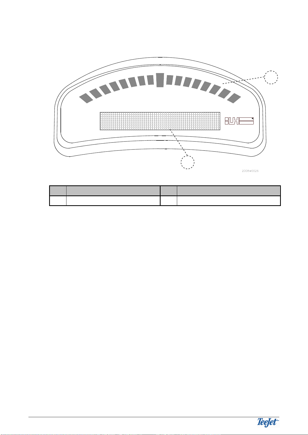
THE CENTERLINE LIGHTBAR
LH AGRO
Pos.
Description Pos.
Description
1 Lightbar lights 2 Menu screen
LIGHTBAR LIGHTS (POS. 1)
An indication of the present position in comparison to the required position.
When driving “on track” the middle light will be lit.
MENU SCREEN (POS. 2)
Operating information and the various menus are displayed here.
AN INTRODUCTION TO PARALLEL SWATHING
Parallel swathing can be carried out in three different ways; driving around the
headland and parallel to a straight line or a curved line. Typically, work will start by
driving around the headland 2 or 3 times and thereafter “side to side” (as with
tramlines).
Whilst driving around the headland it is possible to create a reference line from
which the remainder of the field can be driven parallel to. This reference line is
created by marking 2 points, point A and point B. The shortest possible distance
between 2 points is a straight line and this straight line is the reference line that is
driven parallel to for straight guidance(not the headland).
The reference line can be created, as mentioned before, whilst working the
headland, but also at any other time whilst driving. Once the reference line is
marked, it is possible to drive parallel to this line anywhere in the field.
1
2

C
ENTER
L
INE
O
PERATOR
&
FITTING INSTRUCTIONS
G
ENERAL
O
PERATION
9
STRAIGHT GUIDANCE
Straight guidance is simply driving in a straight line parallel to the reference line
created with points A & B. Once the reference line has been created it is possible
to drive parallel to the left and/or the right of the line and before and/or after the
initial reference points (A & B), the following diagram illustrates this:
The solid line represents the reference line
created with points A & B.
The dashed line shows that parallel lines are
automatically created on the left- and right-
hand side plus in front of and behind the
reference line.
This means that parallel guidance is possible
outside the points A and B
CURVED GUIDANCE
Curved guidance is driving parallel to a curved line in a similar fashion to straight
guidance. Parallel guidance is possible to the left and/or right of the reference line
but not before or after the initial reference points. The following diagram illustrates
this:
The solid line represents the initial
reference line created with points A & B.
The dashed lines show that parallel lines
are automatically created in front of the
initial reference line.
The dashed lines also show that parallel
lines are not created in to the side of the
initial reference points
This means that curved guidance is not
possible outside of the points A and B
HEADLAND GUIDANCE
Headland guidance is driving parallel around the headland of the field. Once the
headland has been completed it is possible to drive to the left and/or to the right of
the initial bout. A reference line (A & B) for straight or curved guidance can be
created whilst in headland mode.
A detailed example of headland guidance can be seen on page 11.
A
B
No guidance
No guidance
A B
G
ENERAL
O
PERATION
C
ENTER
L
INE
O
PERATOR
&
FITTING INSTRUCTIONS
10
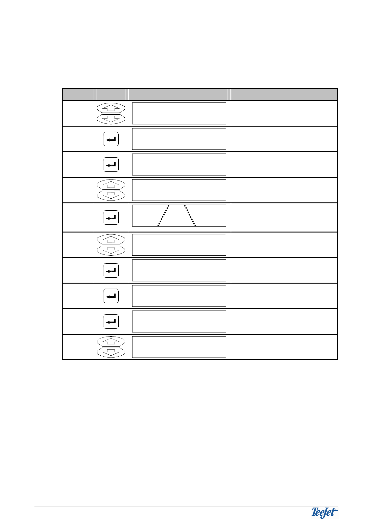
A WORKING EXAMPLE
The following example shows that the headland is driven twice. Two reference
marks are made to create the straight reference line that the rest of the field is to
be driven parallel to:
Step Key Display Description
1
UP
DOWN
Select "Start” to begin real-
time guidance.
2
Start a new field
3
Only displayed if "STATUS” =
OFF under setup.
4
UP
DOWN
Select for headland work.
5
Start working the headland. 2
lines are shown in the
display.
6
UP
DOWN
Prepare for a new reference
line.
7
Start the reference line.
8
Drive the straight line.
9
Stop marking the reference
line.
10
UP
DOWN
Change to straight work.
Straight?
Mark B
Mark A
New A - B
Headland?
Spray On
New?
Start

C
ENTER
L
INE
O
PERATOR
&
FITTING INSTRUCTIONS
G
ENERAL
O
PERATION
11
The first pass is almost finished and the marks for the reference line have been
created (mark A & B) for which the rest of the field will be driven parallel to. See
steps 7, 8, & 9 in the above for marking the reference line).
The second pass of the headland has just been started. Marks A & B were created
in the first pass around the headland.
When changing from the first to the second pass around the headland the
following is displayed:
This shows that a left turn is approaching.
First pass
Mark A Mark B
First pass
Mark A Mark B
Start of the second
pass

G
ENERAL
O
PERATION
C
ENTER
L
INE
O
PERATOR
&
FITTING INSTRUCTIONS
12
The second pass around the headland is finished and work has started parallel to
the straight reference line, which was created with marks A & B during the first
pass around the headland.
The field is finished.
Mark A Mark B

C
ENTER
L
INE
O
PERATOR
&
FITTING INSTRUCTIONS
O
PERATION
13
OPERATION
OPERATING MENU OVERVIEW
GENERAL
Each menu item is described in the following:
Encoding all settings is necessary for correct operation, see ENCODE on
page 17.
NEW?
Select this if starting a new field. Previous fieldwork will be erased (not
encodements).
RESUME?
Select this to continue work in a previously worked field.
APPLY ON/OFF
This function is only displayed if “STATUS” = OFF under encode – see page 19.
If the system is not fitted with an “implement sensor” (see “FITTING THE
CENTERLINE” on page 24) then this function is used to, manually, tell the system
whether the implement is in work or not.
If the system is fitted with an “implement sensor” and “STATUS” = ON under
encode the system will automatically detect if the implement is in work or not.
HEADLAND/STRAIGHT/CURVE AB
Select whether the machine is driving around the headland or driving straight
(parallel to a reference line) – see “AN INTRODUCTION TO PARALLEL
SWATHING”) on page 8.
CLOSE
START
SETUP
TOOLS
NEW?
RESUME?
RIGHT
APPLY OFF
HEADLAND
NEW A-B
AREA
EXIT
APPLY ON
STRAIGHT
MARK A
LEFT
MARK B
PATTERN
CURVE AB
O
PERATION
C
ENTER
L
INE
O
PERATOR
&
FITTING INSTRUCTIONS
14
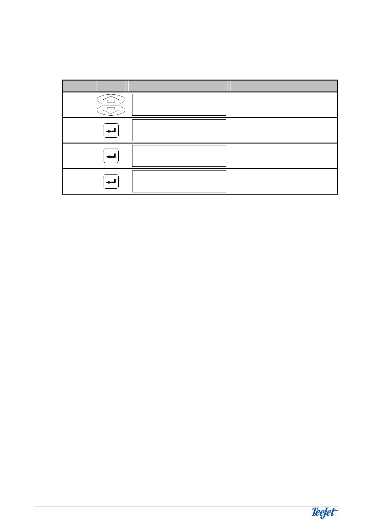
NEW A – B
Selecting this function allows a new reference line to be created. The procedure
for creating a new reference line follows:
Step Key Display Description
1
UP
DOWN
Prepare for a new reference
line.
2
Start the reference line.
3
Drive the straight stretch.
4
Stop marking the reference
line.
All straight guidance work hereafter will be parallel to the reference line. A new
reference line can be created at any time during work in the field by following this
(the above) procedure.
The reference line remains in the memory until either:
1. A new real-time guidance is started (using the "Continue?” function keeps
the reference line).
Or
2. A new reference line is created (only one reference line can be stored at a
time).
Mark B
Mark A
New A - B

C
ENTER
L
INE
O
PERATOR
&
FITTING INSTRUCTIONS
O
PERATION
15
AREA
It is possible to measure and thereafter see, e.g. the size of the field, with this
function.
The field area is automatically calculated from the driven circumference (of, i.e. the
field).
If the field area has not been measured with the CenterLine before then select
whether the actual field boundary is on the RIGHT- or LEFT- hand side of the
implement after selecting the AREA function. The display shows that area is being
measured whilst driving.
The area measurement will automatically stop and close the boundary when the
implement is within 4.5 metres of the start position. The boundary can also be
closed manually by selecting “CLOSE”. When the boundary is closed, the field
size is calculated and the area is saved. The calculated area is displayed for 3
minutes and can be seen again by selecting the “SHOW” function under the AREA
menu.
The calculated area remains in the memory until either:
1. A new real-time guidance is started (using the “Continue?” function keeps
the calculated area).
Or
2. A new area measurement is started.
E-DIF
Using e-Dif is normally not necessary in area where correctional signals
from Egnos are available.
Only displayed if the system is fitted with a RX350P Egnos DGPS receiver
(no. 78-50108).
Calibration for the e-Dif receiver. Please see the description on page 22.

O
PERATION
C
ENTER
L
INE
O
PERATOR
&
FITTING INSTRUCTIONS
16
USING THE RETURN TO POINT FUNCTION
The “Return to point” function is used when a marked position in the field is to be
found again. This function is typically used when work in the field is stopped and
the point at which worked stopped is to be returned to.
The “Return to point” function is operated with the “Return to point” key (pos. 2,
see page 7).
When a certain position is to be marked simply press this key. The marked
position will remain in the memory until either:
1. A new real-time guidance is started (using the “Continue?” function keeps
the marked position).
Or
2. A previously marked position is returned to and the key is pressed again
(3rd.time).
When the marked position is to be found again simply press the key again. The
lightbar guidance lights will show the way to drive and the display will show the
distance (in metres) between the present position and the marked position.
Press the “Menu/Esc” key to exit the “Return to point” function when the previously
marked position has been found.

C
ENTER
L
INE
O
PERATOR
&
FITTING INSTRUCTIONS
E
NCODE
17
ENCODE
SETUP MENU OVERVIEW
START
SETUP
TOOLS
GUIDANCE
WIDTH
ANTENNA
STATUS
ALARM
TO START
NEXT
GPS TYPE
1 Hz MSG
DISTANCE
DIRECTION
FORWARD
BACK
HEIGHT
OFF
ON
ON
OFF
DGPS
GPS
YES
NO
LIGHTBAR SPACING
MODE
TEXT 1
TEXT 2
NEXT
TO START
VEHICLE
SWATH
X-TRACK
SWATH #
SPEED
AREA
COURSE
OFF
SYSTEM UNITS
US
METRIC
LANGUAGE
NEXT
STEER BAR
YES
NO
TO START
S
NEXT
XT
TO START
AHEAD
NEXT

E
NCODE
C
ENTER
L
INE
O
PERATOR
&
FITTING INSTRUCTIONS
18
GENERAL
There are two shortcuts in the setup menus, NEXT and TO START.
Selecting the NEXT function will automatically page back to the main menu for the
sub menu. Therefore, if, i.e. the SYSTEM menu is active and the NEXT function
was selected then the menu will automatically “jump” back to SETUP.
If the TO START function is selected, regardless of what menu is active, then the
system will automatically “jump” to the real-time guidance menu (operation). This
function can, e.g. be used if a setting needs to be altered during operation and
then the guidance task is to be continued.
We recommend encoding the system settings first as these decide, amongst
other things, the units used for operation and the other settings (see page
20).
GUIDANCE
All vehicle and implement related settings are encoded here.
The following settings presuppose that UNITS (in the SYSTEM menu) has been
set to METRIC and that the LANGUAGE is set to ENGLISH:
WIDTH
Encode the distance between the tracks in steps of 10 cm (min = 1m, max =
100m).
This width is typically the working width of the implement. If the encoded width is
set slightly smaller than the actual working width of the implement then chances
for “misses” in the field is reduced. If the encoded width is slightly larger than the
actual width of the implement, then overlapping will be reduced.
AHEAD
Encode, in seconds, how far ahead the Centerline should look ahead (typically set
to 1.5 or 2 seconds).
The look ahead function takes the current speed, direction plus this look ahead
value and calculates where the vehicle will be in relation to the current track. The
value to be encoded depends greatly on the machine operator.
When set to 0 the system does not use this function.
ANTENNA
The DGPS antenna is typically fitted either in front or behind the implement (front
mounted implements). Encode whether the DGPS antenna is in front or behind the
implement plus the distance between the antenna and the implement.
DIRECTION: Select “BACK” if the implement is behind the DGPS antenna.
Select “FORWARD” if the implement is in front of the DGPS
antenna.
DISTANCE: The distance between the DGPS antenna and the implement is
encoded in steps of 10 centimetres (min. = 0m, max. = 300m).
Consider the “drop point” of the implement. If the implement used
is i.e. a fertiliser spreader then the product will hit the ground up to
40 metres behind the DGPS antenna.
HEIGHT: The height from the ground to the DGPS antenna is encoded in
steps of 10 cm (min. = 0m, max. = 10m).

C
ENTER
L
INE
O
PERATOR
&
FITTING INSTRUCTIONS
E
NCODE
19
STATUS
If this setting is encoded to “ON”, then the CenterLine will receive a signal from the
implement telling whether the implement is in work or out of work (see page 24).
This is used for, amongst other things, area measurement and warnings for
previously worked area (see the following alarm description).
If “OFF” is selected (standard setting) then the CenterLine will not give a warning
for previously worked area regardless of whether the implement is in work or out of
work.
ALARM
If “ON” is selected under ALARM then the CenterLine will give a visual warning
when a previously worked area is approached or driven into. APPLIED is shown in
the display when previously worked area is driven in, e.g. the headland.
If “OFF” is selected then no warning will be given when driving in previously
worked areas.
GPS TYPE
If differential corrections are not available, setting this menu item to GPS will allow
work to continue without reference signals.
When the standard setting (DGPS) is used a warning will appear on the
CenterLine and work can not continue should the differential signal be lost.
Accuracy will be greatly reduced if work is carried out without DGPS signals.
We do not recommend changing this setting.
1HZ MESSAGE
If the DGPS receiver being used is not able to send data to the CenterLine at an
acceptable rate it is possible to allow the system to accept DGPS signals from
such a receiver.
When the standard setting (NO) is used a warning will appear on the CenterLine if
the DGPS signals are not being received fast enough.
Accuracy will be greatly reduced if work is carried out with slow DGPS
signals. We do not recommend changing this setting.
LIGHTBAR
Settings related to the lightbar are encoded in the LIGHTBAR menus. A
description of these settings follows:
SPACING
This distance expresses the distance each LED on the lightbar represents. The
spacing can be set from 10 cm to 300 cm in steps of 10 cm.

E
NCODE
C
ENTER
L
INE
O
PERATOR
&
FITTING INSTRUCTIONS
20
MODE
If MODE is set to “VEHICLE” then the middle line on the lightbar represents the
position of the implement. Steer the machine so that the middle line of the lightbar
is moved to the moving light.
If MODE is set to “TRACK” then the middle line of the lightbar represents the track.
Steer the machine so that the moving light is moved to the middle of the lightbar.
TEXT 1 & TEXT 2
Select one of the following text messages (one for TEXT 1 plus one for TEXT 2) to
be displayed whilst working:
X-TRACK: Shows the distance between the required track and the actual
position of the machine.
SWATH #: Shows the actual track number.
SPEED: Shows the present forward speed as kilometres per hour.
AREA: Shows the measured area that has been worked (not to be
confused with the calculated area from the AREA function as
described on page 15).
COURSE: Displays the machine heading in degrees.
OFF: No information is displayed.
STEER BAR?
When the STEER BAR option = “Yes” then all lights will be lit from the centre to
the left or right indicator light, whereas if the STEER BAR option = “No” (standard
setting) then only the left or right indicator light will be lit.
SYSTEM
UNITS
The units used for operation and encoding. Select between US (feet & inches) and
METRIC (metres & centimetres).
LANGUAGE
Select the operating language of the CenterLine.
Table of contents
Other TeeJet Technologies Car Navigation System manuals


