TeeJet Technologies ISOBUS IC18 User manual
USER MANUAL
IC18 SPRAYER
JOB COMPUTER
Software version 1.06

COPYRIGHTS
© 2012 TeeJet Technologies. All rights reserved. No part of this document or the computer programs described in it may be reproduced,
copied, photocopied, translated, or reduced in any form or by any means, electronic or machine readable, recording or otherwise, without
prior written consent from TeeJet Technologies.
TRADEMARKS
Unless otherwise noted, all other brand or product names are trademarks or registered trademarks of their respective companies or
organizations.
LIMITATION OF LIABILITY
TEEJET TECHNOLOGIES PROVIDES THIS MATERIAL “AS IS” WITHOUT WARRANTY OF ANY KIND, EITHER EXPRESSED OR
IMPLIED. NO COPYRIGHT LIABILITY OR PATENT IS ASSUMED. IN NO EVENT SHALL TEEJET TECHNOLOGIES BE LIABLE FOR
ANY LOSS OF BUSINESS, LOSS OF PROFIT, LOSS OF USE OR DATA, INTERRUPTION OF BUSINESS, OR FOR INDIRECT,
SPECIAL, INCIDENTAL, OR CONSEQUENTIAL DAMAGES OF ANY KIND, EVEN IF TEEJET TECHNOLOGIES HAS BEEN ADVISED OF
SUCH DAMAGES ARISING FROM TEEJET TECHNOLOGIES SOFTWARE.
To ensure optimal use of the equipment, please read this manual thoroughly. Please contact TeeJet Technologies Customer Support or an
authorized TeeJet Technologies dealer if additional support is required.
RESPONSIBILITY FOR USE OF THIS PRODUCT
Regarding responsibility for use of this product, we refer to our sales and delivery terms which states:
Product Usage
Any use of the product is at the sole risk of the buyer. The buyer is therefore not entitled to any form for compensation caused by, for
example, any of the following:
►Disturbance to/from any electronic services or products that do not conform to the standards for CE marketing;
►Missing or poor signal coverage or a succession hereof from external transmitters/receivers used by the buyer; Functional faults which
apply to or from a PC-program or PC equipment not delivered by the seller;
►Faults that may arise from the buyers’ negligence to react to warnings and fault messages from the product or that can be traced to
negligence and/or absent constant control of the work carried out in comparison to the planned job.
When implementing any new equipment the buyer must take great care and pay attention. Any doubts as to the correct operation/use
should result in contacting the seller’s service department.

i
98-05204 R1 UK
OVERVIEWSETUPAPPENDIX GETTING STARTEDOPERATION
ISOBUS Job Computer : IC18 Sprayer
Table of Contents
CHAPTER 1– PRODUCT OVERVIEW 1
OPTIONAL SYSTEM COMPONENTS 1
CHAPTER 2 – GETTING STARTED 3
START UP 3
APPLICATION MODE 3
PAGE LAYOUT AND NAVIGATION 4
Home Screen...................................................................................................................................................................4
Transport Mode................................................................................................................................................................4
Operation Mode...............................................................................................................................................................5
Main Setup Mode.............................................................................................................................................................6
Main Setup Menu Icons and Section Overviews ...................................................................................................7
CHAPTER 3 – MAIN SETUP IN SPRAYER MODE 8
Main Setup Screen ................................................................................................................................................................................ 8
Master Screen ......................................................................................................................................................................................... 9
Home Screen........................................................................................................................................................................................... 9
COUNTERS 10
Trip Counters.........................................................................................................................................................................................11
Active Trip Counter .............................................................................................................................................. 11
Area Counter........................................................................................................................................................ 11
Distance Counter ................................................................................................................................................. 11
Time Counter ....................................................................................................................................................... 11
Volume Counter ................................................................................................................................................... 11
Campaign Counters............................................................................................................................................................................11
Area Counter........................................................................................................................................................ 11
Volume Counter ................................................................................................................................................... 11
Time Counter ....................................................................................................................................................... 11
Total Counters.......................................................................................................................................................................................12
Area Counter........................................................................................................................................................12
Volume Counter ...................................................................................................................................................12
Time Counter .......................................................................................................................................................12
Export Counters ...................................................................................................................................................................................12
JOB PARAMETERS 13
Active Trip Counter ..............................................................................................................................................13
Preset Application Rates......................................................................................................................................13
Nozzle..................................................................................................................................................................13
MACHINE 14
Filling........................................................................................................................................................................................................14
Actual Content .....................................................................................................................................................14
Density.................................................................................................................................................................14
Density Factor......................................................................................................................................................15
Full Tank...............................................................................................................................................................15
Operation ...............................................................................................................................................................................................15
Application Rate Step ..........................................................................................................................................15
Speed Source ......................................................................................................................................................15
Simulated Speed..................................................................................................................................................15
Implement Parameters......................................................................................................................................................................16
Section Width.................................................................................................................................................................16
Boom Section Width ............................................................................................................................................16
One-Touch Equal Widths .....................................................................................................................................16

ii www.teejet.com
OVERVIEW SETUP APPENDIXGETTING STARTED OPERATION
ISOBUS Job Computer : IC18 Sprayer
Nozzle Preset Setup......................................................................................................................................................16
Nozzle Preset.......................................................................................................................................................16
Nozzle Type .........................................................................................................................................................16
Nozzle Size..........................................................................................................................................................16
Low Pressure Limit ..............................................................................................................................................17
High Pressure Limit..............................................................................................................................................17
Reference Flow....................................................................................................................................................17
Reference Pressure.............................................................................................................................................17
Factory Settings...................................................................................................................................................17
Regulation Parameters..................................................................................................................................................18
Valve Calibration, Rough .....................................................................................................................................18
Valve Calibration, Fine.........................................................................................................................................18
Nozzle Spacing....................................................................................................................................................18
Regulation Mode..................................................................................................................................................18
Calibrations............................................................................................................................................................................................19
Implement Speed Sensor ..............................................................................................................................................19
Manual Calibration...............................................................................................................................................19
Automatic Calibration...........................................................................................................................................19
Flow Sensor...................................................................................................................................................................19
Manual Calibration...............................................................................................................................................19
Automatic Calibration...........................................................................................................................................19
Alarm Congurations.........................................................................................................................................................................20
CAN Speed Source Timeout................................................................................................................................20
Active Trip Count Information...............................................................................................................................20
Tank Content Minimum ........................................................................................................................................20
OEM ..........................................................................................................................................................................................................20
USER INTERFACE 21
Use Preferred VT.................................................................................................................................................21
This IC18..............................................................................................................................................................21
Pair with Switchbox..............................................................................................................................................21
Pair with BoomPilot ECU .....................................................................................................................................21
Currently Paired With Information........................................................................................................................21
Show Number on Soft Key...................................................................................................................................21
Sprayer Number (FI)............................................................................................................................................21
COMMUNICATION 22
HELP 22
Diagnostic ..............................................................................................................................................................................................23
Test Input .......................................................................................................................................................................23
Test Output ....................................................................................................................................................................23
Liquid Valve PWM Dutycycle ...............................................................................................................................23
Liquid Valve Direction ..........................................................................................................................................23
Master Valve ........................................................................................................................................................23
Section Valves .....................................................................................................................................................23
VT Data..........................................................................................................................................................................24
TECU.............................................................................................................................................................................24
About .......................................................................................................................................................................................................24
CHAPTER 4 – OPERATION MODE 25
AUTOMATIC OR MANUAL REGULATION MODE 25
OPERATION MODE OVERVIEW 26
Keys Descriptions..........................................................................................................................................................27
Section and Icon Descriptions .......................................................................................................................................27
Master Screen .......................................................................................................................................................................................28
Home Screen.........................................................................................................................................................................................29
APPLICATION RATE OPTIONS 29


iii
98-05204 R1 UK
OVERVIEWSETUPAPPENDIX GETTING STARTEDOPERATION
ISOBUS Job Computer : IC18 Sprayer
Target Rate Percentage Increase/Decrease................................................................................................................................29
Regulation Valve Manual Open/Close..........................................................................................................................................29
Target Rate .............................................................................................................................................................................................30
With Switchbox ..............................................................................................................................................................30
Without Switchbox .........................................................................................................................................................30
BOOM SECTIONS 31
On/O Sections from the Left or Right........................................................................................................................................31
Without Switchbox .........................................................................................................................................................31
With Switchbox ..............................................................................................................................................................31
Start/Stop Application.......................................................................................................................................................................32
Without Switchbox .........................................................................................................................................................32
With Switchbox ..............................................................................................................................................................32
Master Stop Key ...................................................................................................................................................................................32
With Switchbox ..............................................................................................................................................................32
INFORMATION KEY 33
TRANSPORT MODE 34
APPENDIX A - FACTORY SETTINGS & RANGES 35
APPENDIX B - UNIT SPECIFICATIONS 37

1
98-05204 R1 UK
OVERVIEWSETUPAPPENDIX GETTING STARTEDOPERATION
ISOBUS Job Computer : IC18 Sprayer
CHAPTER 1– PRODUCT OVERVIEW
Congratulations on the purchase of your new IC18 ECU built on the ISOBUS architecture. This IC18 unit has the capability of either
sprayer or NH3 control when integrated into the implement of either capability. When used within the guidelines of this manual, the IC18
controller will be a reliable application tool.
This manual covers the Sprayer functions of the IC18 ECU. For NH3 functions, see manual number 98-05230.
Use with your existing VT or Matrix® 570VT
• Works seamlessly and displays on any ISOBUS VT
• Easy navigation menu and data rich display
• IC18 Sprayer ECU suitable for use with NH3 and liquid fertilizer
• Automatic boom section control upgrade option
• Variable rate control available providing your VT has GPS and task control capability
• Easy navigation menu and data rich display
• Add additional ISOBUS ECUs as your needs change
• Provides basic rate control
• Standardized plugs, cables and software simplify installation and connectivity and result in true “plug and play” technology. IC18 ECU
resides on the implement, reducing hardware in the cab
Figure 1-1: IC18 Job Computer
OPTIONAL SYSTEM COMPONENTS
Matrix 570VT
The Matrix 570VT is a simple to operate, ISOBUS-certied 14.5 cm (5.7″) colour touch screen display suitable for bright daylight and
nighttime operation
Figure 1-2: Matrix 570VT
2www.teejet.com
OVERVIEW SETUP APPENDIXGETTING STARTED OPERATION
ISOBUS Job Computer : IC18 Sprayer
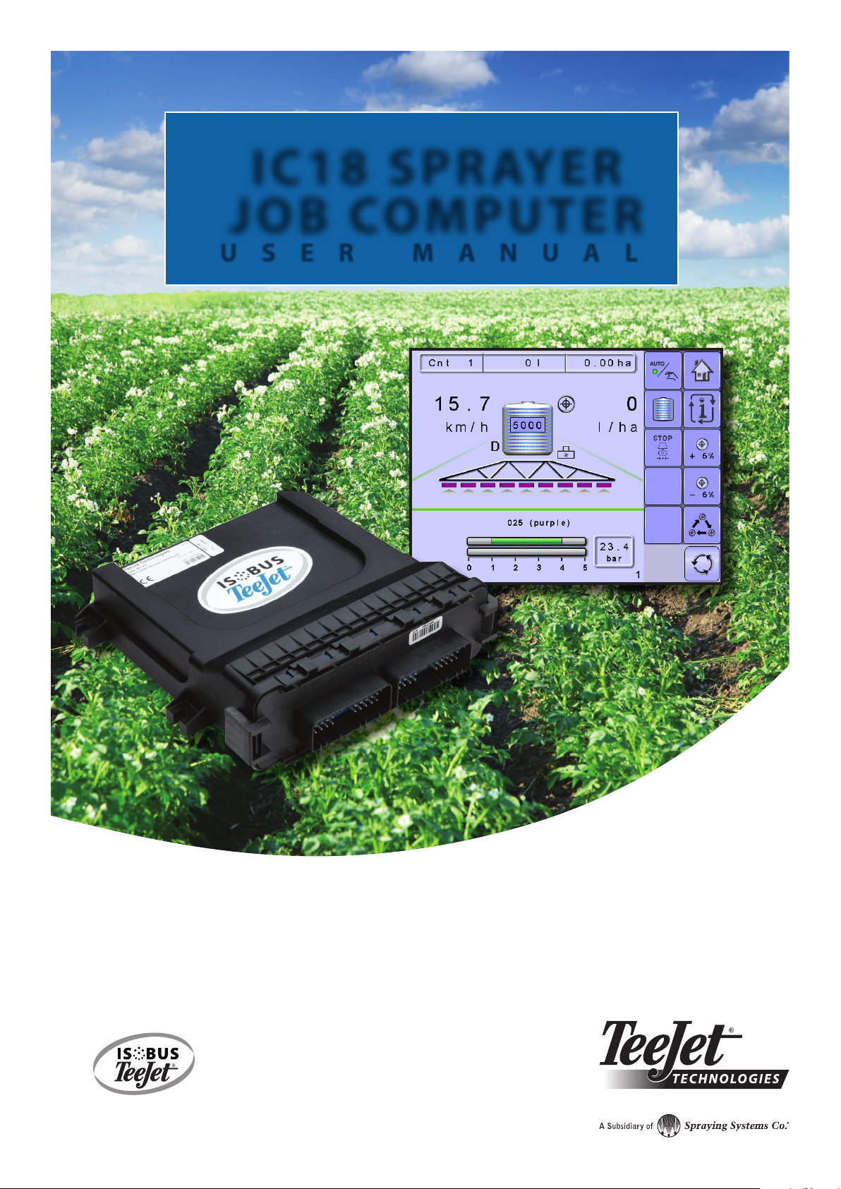
Switchbox
Manual section control with remote master capibility. The switchboxs are available in two congurations.
►9 sections output or 8 sections and a master output
►6 sections output or 5 sections and a master output
Figure 1-3: Switchboxes
IC18 Spreader Electronic Control Unit
Use with your existing VT or the Matrix 570VT for dry product application
• Works seamlessly and displays on any ISOBUS VT
• Easy navigation menu and data rich display
• Add additional ISOBUS ECUs as your needs change
• Provides basic rate control or variable rate if the connecting VT has variable rate task control capabilities
• Standardized plugs, cables and software simplify installation and connectivity and result in true “plug and play” technology. IC18 ECU
resides on the implement, reducing hardware in the cab
Figure 1-4: IC18 Spreader Electronic Control Unit
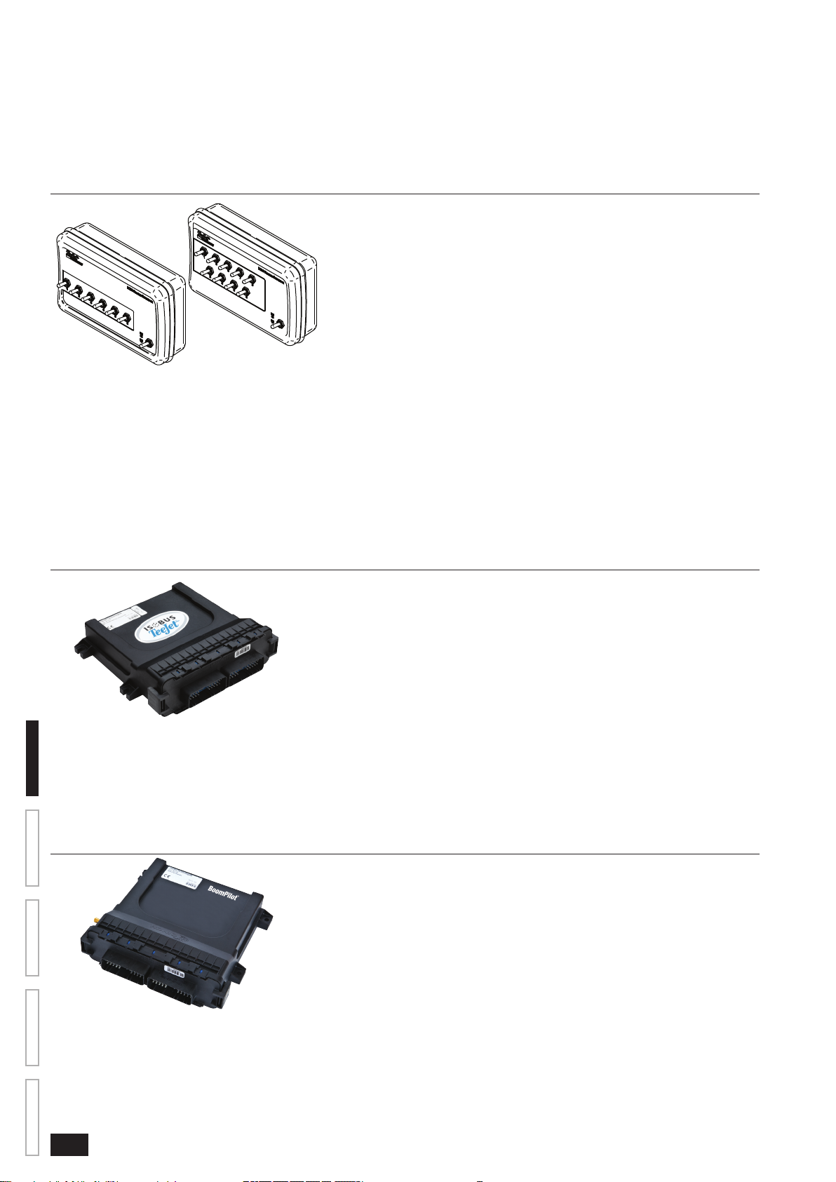
BoomPilot Electronic Control Unit for IC18
BoomPilot (automatic boom section control) is possible in combination with software built into the IC18 Sprayer/NH3 Electronic Control Unit
(ECU). The ECU should be combined with the appropriate cable to interface with your BoomPilot system, spray controller and/or spraying
machine for quick and easy installation. Electronic Control Units and their related cables are designed to control as many boom sections as
the spray controller to which they are connect, up to a maximum of 9 boom sections.
Figure 1-5: BoomPilot Electronic Control Unit

3
98-05204 R1 UK
OVERVIEWSETUPAPPENDIX GETTING STARTEDOPERATION
ISOBUS Job Computer : IC18 Sprayer
CHAPTER 2 – GETTING STARTED
• A rm touch is required when selecting a screen icon.
• Settings are NOT automatically saved when selected. The ACCEPT KEY must be selected to save the setting. Select the
ESCAPE KEY to escape without saving settings and return to the previous menu.
• The console needs to be cycled off and back on when changing or attaching equipment to the system.
• The menu structure on your display might vary from the one displayed in this User Manual depending on the virtual terminal being
used.
START UP
Power is continuously supplied to the job computer. The virtual terminal will give access to the job computer options and operation.
Figure 2-1: Master Screen - Crop Sprayer Mode
Matrix VT Setup Key
IC18 Crop Sprayer
Master Screen Key
Other options as available on
ISOBUS system
APPLICATION MODE
The IC18 job computer is programed to be either a sprayer or NH3 applicator. This setting has been established before leaving the factory,
but it can be changed after purchase with assistance from TeeJet Technologies Customer Service or your local dealer through the OEM
setup menu options.
Figure 2-2: Crop Sprayer
Cnt 1
5.0 42
470 l
0
bar
1.14 ha
+ 5%
1311 l/hakm/h
Figure 2-3: NH3 Applicator
Cnt 1
0.0
0.0
0.0
0.0
0 kgN 0.00 ha
+ 5%
1311 kg/min
kg/ha
km/h
kg/ha
This manual discusses specically the functions and options in Crop Sprayer Mode. See the specic IC18 NH3 User Manual for functions
and options in NH3 Mode.

4www.teejet.com
OVERVIEW SETUP APPENDIXGETTING STARTED OPERATION
ISOBUS Job Computer : IC18 Sprayer
PAGE LAYOUT AND NAVIGATION
The Master Screen gives access to the systems currently available on your VT. From the Master Screen, the Home Screen gives access
to the IC18’s available functions.
Home Screen
The Home Screen gives access to the IC18’s available functions: Operation Mode, Transport Mode and Main Setup.
Figure 2-4: Home Screen - Crop Sprayer Mode
Operation Mode
Regulation Mode
Current selection, Auto/Manual, is highlighted with a green dot.
Main Setup Mode
Toggle Preset Target Rate
Quick View
Information Based on Current Active Trip
Master Screen Key
Transport Mode
Transport Mode
While in Transport Mode, all operation functions are locked off and cannot be activated.
Figure 2-5: Transport Mode
Home Key
Speedometer
Master Screen Key
Table of contents
Other TeeJet Technologies Control Unit manuals

Popular Control Unit manuals by other brands

Festo
Festo Compact Performance CP-FB6-E Brief description

Elo TouchSystems
Elo TouchSystems DMS-SA19P-EXTME Quick installation guide

JS Automation
JS Automation MPC3034A user manual

JAUDT
JAUDT SW GII 6406 Series Translation of the original operating instructions

Spektrum
Spektrum Air Module System manual

BOC Edwards
BOC Edwards Q Series instruction manual

KHADAS
KHADAS BT Magic quick start

Etherma
Etherma eNEXHO-IL Assembly and operating instructions

PMFoundations
PMFoundations Attenuverter Assembly guide

GEA
GEA VARIVENT Operating instruction

Walther Systemtechnik
Walther Systemtechnik VMS-05 Assembly instructions

Altronix
Altronix LINQ8PD Installation and programming manual


