Teknic E3PS12-75 User manual

Teknic E3PS12-75 Power Supply Quick Reference
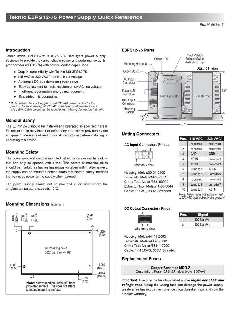
Teknic model E3PS12-75 is a 75 VDC intelligent power supply
designed to provide the same reliable power and performance as its
predecessor product, SSt-3PS12-75, but with several added
capabilities:
● 100% Drop-in compatibility with Teknic SSt-3PS12-75.
● 115 VAC or 230 VAC input compatible.
● Automatic DC bus dump on power down.
● High, medium, and low AC line voltage selector switch.
● Intelligent regenerative energy management.
Introduction E3PS12-75 Nomenclature
Fuses (x2)
(see below)
DC Output
Connector
AC Input
Connector
Input Voltage
Selector Switch
Status LED
P1
P3
Mounting Hole (x4)
Mounting
Bracket
Circuit Board
Main Capacitor Transformer
(behind main cap)
The E3PS12-75 should be installed and operated as specified herein.
Failure to do so may impair or defeat any protections provided by the
equipment. Please read and follow all instructions before installing or
operating this device.
General Safety
The power supply should be mounted behind covers or machine skins
that can only be opened with a tool. The covers or machine skins
should be marked as having hazardous voltages within. Alternatively,
the supply can be mounted behind doors that have a safety interlock
that removes power to the supply when opened.
The power supply should not be mounted in an area where the
ambient temperature exceeds 40°C.
Mounting Safety
Replacement Fuses
Description: Fuse, 3AB, 2A, slow blow, 250VAC
Cooper Bussman MDQ-2
Important: Use only the fuse type listed above regardless of AC input
line voltage (115 or 230 VAC). Using the wrong fuse can damage the
power supply, create a fire hazard, cause nuisance circuit breaker
trips, and void the product warranty.
Rev. J 8/6/12
ANNI
BII
TII
JJL
SYD
Housing: Molex/39-01-2100
Terminals: Molex/39-00-0059
Crimp Tool: Molex/638190900
Cable: 18AWG, 300V, Stranded
Housing: Molex/44441-2002
Terminals: Molex/43375-0001
Crimp Tool: Molex/63811-7200
Cable: 14-16AWG, 600V, Stranded
Mating Connectors
AC Input Connector / Pinout
DC Output Connector / Pinout
1
2
3
4
10
5
7
8
9
6
Pos. 115 VAC 230 VAC
NC
NC
AC IN
NC
NC = No Connect
AC IN
GND
NC
NC
Jump to 9
Jump to 7
NC
NC
Jump to 9
NC
Jump to 7
GND
AC IN
AC IN
Jump to 10
Jump to 6
1
2
Pos. Signal
DC Bus (V+)
DC Bus (V-)
1
10 5
6
1 2
Pin 1
Pin 1
Mounting Dimensions inch (mm)
Note: screw head protrudes.09” from
projected surface. This does not affect
standard mounting surface.
7.786
(197.76)
4.100
(104.14)
7.155
(181.74)
0
0.255
(6.48)
.300
(7.62)
4.050
(102.87)
4.964
(126.09)
8.087
(205.41)
All Mounting holes
0.25” dia. thru +/- .02”
0.090
(2.29)
0
0
8.1”
3.9”
5.0”

RoHS Status RoHS compliant
Rated Load Current (RMS) 3.5 amps
12 ampsPeak Current Capability
82.0 VDC max.Ouput Voltage, No Load
72.0 VDC min.
Output Voltage @ Rated Current
Energy Storage 81 joules
Weight 12 lbs.
Input Voltage (110 VAC nom. range) 96 – 131 VAC
Power Consumption (max.) 382 W
In-rush Current (@115 VAC / 230 VAC) 50 A (pk) / 25 A (pk)
Input Frequency Range 50 - 60 Hz
Output Capacitance (min.) 20,000 uF
Input Voltage (220 VAC nom. range) 192 – 262 VAC
Specification Value
Dimensions 8.1” x 5.0” x 3.9”
CE/UL Certification Pending, 2012-Q3
Temperature 0-40° C
10% - 90%Humidity (non-condensing)
Pollution Degree 2Environment Type
Operating Environment:
The Input Voltage Selector Switch is a 3-position slide switch used to
set one of three tap points on the transformer. This provides a conve-
nient way to adjust for low, medium, or high local line voltage. Note:
moving this switch to a lower setting makes the DC output voltage
higher, and vice versa.
The E3PS12-75 is warranted to be free from defects in workmanship
and materials for a period of 36 months from date of purchase.
Three Year Warranty
Procedure: Setting The Input Voltage Selector Without Tools
Note: Remove AC power each time before moving this switch.
1. Set switch to highest setting (126.5/253).
2. Turn on AC line power to supply.
3. Status LED should blink rapidly (16 Hz).
4. Move switch to progressively lower settings until
Status LED turns on solid. See Regen Note below.
5. When Status LED turns on solid, back up one position.
6. Status LED will blink rapidly if set correctly.
This switch is located
behind the main capacitor
16 Hz
3 Hz
50%Rapid Blink: Normal operating mode. No action required.
No action required. This is an informational code that
will not affect power supply operation. Note: blink
code will persist until AC power is cycled.
Blink: Normal operating mode. A regen
event occurred at least once since AC power
was last applied.
On-Normal
Regen Event Occurred 50%
0.5 HzUpgrade to higher regen capacity supply. Note: blink
code will persist until AC power is cycled.
Strobe: Continuous regen capacity was
exceeded since AC power was last applied.
Regen Capacity
Exceeded
2.5%
Condition Description User Action
LED Blink
Frequency
Duty Cycle
(% on)
LED Blink Codes (Note: LED is off when DC voltage < 25 VDC)
100%LED on solid: DC output voltage > 85 VDC Move Input Voltage Selector Switch to higher setting.
Rapid blink will occur when the Voltage Selector
Switch is set correctly.
Input Voltage Switch set
too low
Setting The Input Voltage Selector Switch Specifications
Accessory Cables (sold separately)
Note: Values (103.5, 115, 126.5)
apply to 115 VAC nominal installations;
values (207, 230, 253) apply to
230 VAC nominal installations.
103.5 115 126.5
207 230 253
Low Med. High
Teknic P/N: E3PS12-PIGTAIL
Description: Adapter pigtail for DC output. Makes
E3PS12-75 output compatible with SSt-3PS12-75.
78.5”
Teknic P/N: E3PS12-CABLE110
Description: 110 VAC power cable. Standard
grounded plug to Molex Mini-Fit Jr. 10 position
connector. (see page 1 for connector PN).
Teknic P/N: PC-SBR-72
Description: Power cable, Sabre to Sabre from
E3PS12-75 to Eclipse or Meridian 4xx and 5xx.
Mate-n-Lok 2 Sabre-2
Sabre-2Sabre-2
72”
When an axis decelerates rapidly the motor behaves like a generator,
sending energy from the motor phases back into the power supply.
This becomes a problem when this regenerated energy exceeds the
supply’s ability to absorb it, and can cause the DC output to spike.
The E3PS12-75 automatically channels the right amount of regener-
ated energy back into the supply, while safely dissipating the rest
across a bank of dump resistors (see note below). This has the dual
benefit of capturing and using “free” energy while protecting the
power supply from potentially damaging voltage levels.
Regenerative Energy Management
19.5”
Annika
Elizabeth
Regen Note: The first few times the supply dissipates energy
across the dump resistors a small amount of smoke may be seen.
This is normal and will stop after the initial outgassing cycle occurs.
Other Teknic Power Supply manuals
