Tekno EB 410 Instruction Manual


Introduction
Additional equipment and parts needed:
•
2 Channel radio and receiver
•
1/10th scale ESC and motor system
•
Low prole or standard size high torque steering servo (at least 150 oz/in)
* Running less than the recommended rating will increase the chance of premature servo failure.
•
2S (2 cell, 7.4v) shorty LiPo battery
•
Paint for body
•
1/10th scale 4x4 buggy wheels & tires, CA glue (or premounts)
•
48 pitch pinion 15 tooth - 30 tooth
Tools needed:
•
Hex drivers 1.5mm (TKR1104), 2.0mm (TKR1105), 2.5mm (TKR1106)
•
Nut drivers 5.5mm (TKR1108), 7.0mm (TKR1109)
•
Hobby knife
•
Needle-nose pliers
•
Shock tool (TKR1115) OR adjustable (Crescent) wrench (for shock assembly)
•
4mm turnbuckle wrench (TKR1103)
•
5.5/7.0 two sided wrench (TKR1119)
Disclaimer: Tekno RC is not responsible or liable for any property or personal damage, loss, or injury incurred as a
result of using this product. This kit is meant for use by persons 14 years of age or older and in the strict connes of
a legally permitted RC track or facility.
Warnings: Always double-check that your radio gear is working properly before operating vehicle. Never operate the
vehicle indoors (unless the RC track is an indoor facility). Use caution while operating vehicle so as not to collide with
people who may be turn marshalling or who might otherwise not be aware that a fast moving RC vehicle is in the vicinity.
Warranty: We warrant that the parts included in this kit are free from defects. If you nd a defective part in your kit,
please contact us @ [email protected] and we will help you to resolve the issue. We do not warranty parts that may be
broken during operation of the vehicle or otherwise. Refer to the end of this instruction manual for a listing of
spare/replacement and option parts. All spare parts and other info are available on our website (www.teknorc.com)
and through our network of domestic and international dealers and distributors.
Thank you for purchasing the Tekno RC EB410 1/10th Scale 4WD Competition Electric buggy kit.
We are always working on new projects, so please REGULARLY check our website
at www.teknorc.com or our Facebook page at www.facebook.com/teknorc
for the latest news, parts, and kits.
Take your time! When you work your way through these building instructions, keep an eye out
for the following important indicators below:
•
RED TEXT - This indicates important areas of the build process that should be observed.
•
YOUTUBE - We also have many useful build videos on Youtube, so be sure to check these out!
https://www.youtube.com/c/teknorc
Thread Lock icons
Thread lock is always used when a screw is inserted into any metal part. (Included with kit)
Thread
Lock
Grease icons
Grease is usually used on areas with movement and for sealing. (Included with kit)
Grease

TKR6517
TKR5144
Bag A
Center Dierential
(overview)
TKR6522
TKR6513X
TKR6550
TKR6550
TKR6515
TKR6511
*TKR6670
(Option)
TKR5144
TKR6517
TKR6515
Step
A-2
Step
A-4
Fill Level
Step
A-3
Step
A-1
TKR5144
Dierential 0-rings
x2
TKR6517
Dierential Shims (5x14mm)
x2
TKR1303
M2.5x10mm Flat Head Screw
x4
TKR1303 x4
TKR6550
TKR6513X
Di
Oil
TKR6522
*TKR6670
(Option)
TKR6514
TKR6514
TKR6514
TKR6514
TKR6517
TKR6550
TKR5144
TKR1303 x4
3
Grease
Grease
Grease
Grease
Fill with #15,000 oil to
1mm below full
DO NOT OVER FILL
Note: Apply grease to the
groove in the outdrive.
Note: These screws
only need to be snug.
Do not over-tighten
or the internal gears
will bind up.
Note: Apply grease to the
groove where the o-ring is
placed as well as the o-ring itself.
TKR6514
TKR6514
Note: Gears will feel a bit tight at first. Please
run 3-4 packs on the track for break-in
before evaluating the internal gear mesh.
Once broken in, it is advised to rebuild each di
with fresh oil. Once complete, the dis will be
smooth and race ready.

Bag B
Front and Rear Dierential
(overview)
TKR6512
TKR6513X
TKR6550
TKR6515
TKR6511
TKR5144
TKR6517
TKR1303 x4
TKR6514
TKR6514
TKR6515
TKR5144
TKR1303 x4
4
Grease
Step
B-1
Step
B-2
Repeat for rear di
Fill Level
Di
Oil
Step
B-3
Step
B-4
Repeat for rear di
TKR5144
Dierential 0-rings
x4
TKR6517
Dierential Shims (5x14mm)
x4
TKR1303
M2.5x10mm Flat Head Screw
x8
Grease
TKR6513X
Repeat for rear di
Fill FRONT with #15,000 oil
Fill REAR with #7,000 oil
to 1mm below full
DO NOT OVER FILL
Repeat for rear di
TKR6517
TKR5144
Grease
Grease
TKR6550
TKR6514
TKR6514
TKR6512
TKR6514
TKR6514
Note: Apply grease to the
groove in the outdrive.
Note: Gears will feel a bit tight at first. Please
run 3-4 packs on the track for break-in
before evaluating the internal gear mesh.
Once broken in, it is advised to rebuild each di
with fresh oil. Once complete, the dis will be
smooth and race ready.
Note: Apply grease to the
groove where the o-ring is
placed as well as the o-ring itself.
TKR6550
TKR6517
TKR6550

TKR1221
TKR1221
TKR1221
TKR6627
TKR6627
TKR6627
TKR6627
TKR1402
TKR1402
TKR1402
TKR6526
TKR6526
TKR6207
TKR6207
TKR1221
M3x8mm Washer
x8
TKRBB040725
TKRBB040725
TKR6526
TKR6208
TKR6208
TKR6208
TKRBB040725
TKRBB040725
TKRBB040725
TKRBB040725
TKRBB040725
TKRBB040725
TKR6526
TKR6526
TKR6526
Step
C-1
Step
C-2
TKRBB040725
Ball Bearing (4x7x2.5)
x4
Thread
Lock
TKR6207
M3x6mm Ball Stud
x1
TKR6208
M3x8mm Ball Stud
x2
TKR1402
M3x8mm Button Head Screw
x2
Note: These screws
only needs to be
snug. Do not
overtighten.
Bag C
Steering Assembly
(overview)
5
TKR1301
TKRBB10154
TKRBB10154
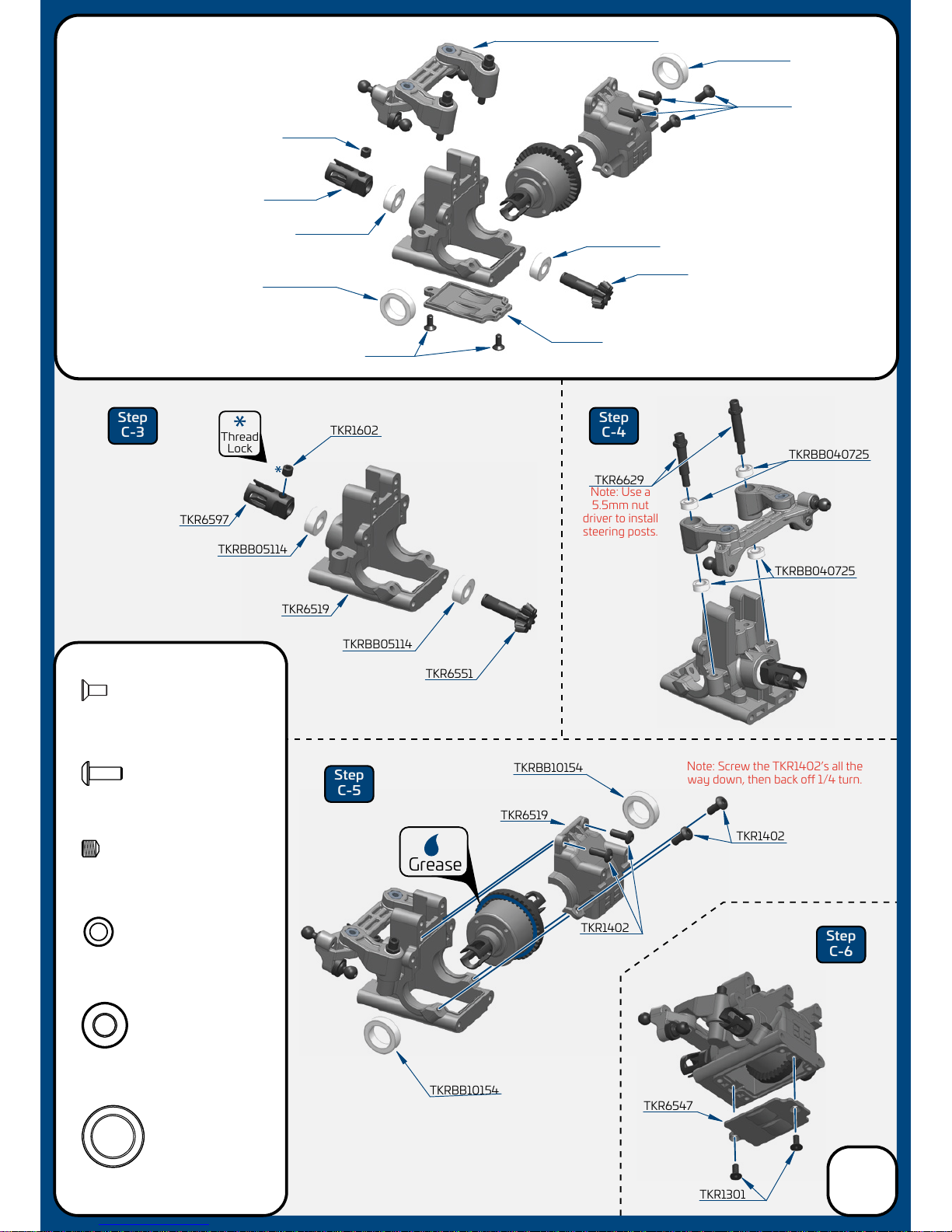
TKR1602
TKRBB10154
TKRBB10154
TKR1301
TKRBB05114
TKR6629
TKR6551
TKRBB05114
TKRBB05114
TKRBB05114
TKR6551
TKR6547
TKR6519
TKR6597
TKR6547
TKRBB05114
Ball Bearing (5x11x4)
x2
TKR1602
TKR6597
(assembly from previous page)
Step
C-3
Step
C-4
Step
C-5
Step
C-6
TKR1301
M2.5x6mm Flat Head Screw
x2
TKR1402
M3x8mm Button Head Screw
x4
TKR1602
M4x4mm Set Screw
x1
TKRBB10154
Ball Bearing (10x15x4)
x2
TKRBB040725
Ball Bearing (4x7x2.5)
x4
TKRBB040725
TKRBB040725
TKR1402
Thread
Lock
Grease
TKR6519
TKR1402
TKR1402
Note: Use a
5.5mm nut
driver to install
steering posts.
Note: Screw the TKR1402’s all the
way down, then back o 1/4 turn.
Bag C
Front Bulkhead Assembly
(overview)
6

Step
D-1
Step
D-2
Step
D-3
Step
D-4
Step
D-5
Step
D-6
TKRBB05114
Ball Bearing (5x11x4)
x2
TKR1201
M3 Locknut Black
x2
TKR1301
M2.5x6mm Flat Head Screw
x2
TKR1402
M3x8mm Button Head Screw
x4
TKR1403
M3x10mm Button Head Screw
x4
TKR1405
M3x14mm Button Head Screw
x2
TKR1411
M3x25mm Button Head Screw
x2
TKR1602
M4x4mm Set Screw
x1
TKRBB10154
Ball Bearing (10x15x4)
x2
TKR6208
M3x8mm Ball Stud
x2
CA
Glue
Bag D
Rear Bulkhead/
Wing Mount
Assembly
(overview)
Thread
Lock
Thread
Lock
TKR6208
TKR6538
TKR6519
TKR6581
TKR6546
TKR1201
TKR1602
TKR6597
TKR1403 TKR1411
TKR6547
TKRBB05114
TKR6551
TKRBB05114
TKR6597
TKR1602
TKRBB05114
TKR6551
TKR6665
TKR6665
TKR1405
TKR6208
TKR1403
TKR1403
TKR6519
TKR6519
TKRBB10154
TKRBB10154
TKR1402
TKR6581
TKR6547
TKR6546
TKR6538
TKR6546
TKR1403
TKR1405
TKRBB10154
TKR1301
TKR1301
TKR1411
TKR1402
4pcs
Grease
TKR1402
*TKR6582C
*TKR6582XC
(Option)
*TKR6582C
*TKR6582XC
(Option)
*TKR6665A
(Option)
TKR1201
Build Tip: Apply a bit of
CA glue to help keep
these nuts in place during
maintenance and rebuilds.
Note: Screw the TKR1402’s
all the way down, then back o 1/4 turn.
7

Stock Position
(”D” Block)
Stock Position
(”C” Block)
TKR1601
TKR6524
TKR6610 - 1.7mm
TKR6547
Note: With these center dot
inserts, Rear Toe = 1.5°
Note: Refer to page
26 for setting droop.
Note: With these center dot
inserts, Anti-Squat = 2°
Note: Do not over-tighten.
TKR6544
TKR6544
TKR6547
TKR6542
TKR1601
TKR6544
TKR1463
TKR6544
TKR6544
Bag E
Rear End
Assembly
Below options sold separately.
*TKR6610 - 1.5mm
*TKR6610 - 1.6mm
*TKR6610- 1.8mm
*TKR6610- 1.9mm
(Option)
*TKR6542B
(Option)
*TKR6543B
(Option)
Thread
Lock
TKR1405
TKR1405
TKR6523
TKR6543
TKR1601
TKR6555
TKR6206
TKR6253
TKR1611
x5
TKR1601
M3x4mm Set Screw
Step
E-1
Step
E-2
Step
E-3
TKR1405
M3x14mm Button Head Screw
x4
TKR1463
M2.5x6mm Button Head Screw
x2
TKR1611
M4x8mm Set Screw
x2
TKR6206
M3x6mm Ball Stud
x2
TKR1463
8
large shim
goes towards
the front
Wheelbase Shims
1
.5
large 1mm
front
rear
small .5mm
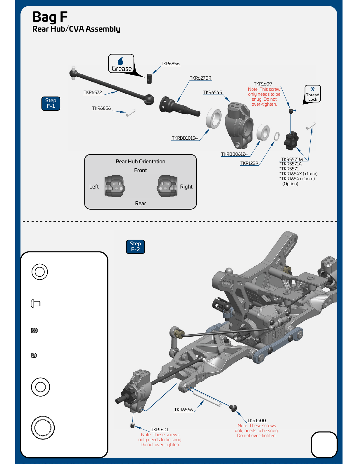
TKR6856
TKR6856
TKR6270R
TKR6545
TKRBB10154
TKRBB06124
TKR5571M
TKR1609
TKR1229
TKR6572
TKRBB10154
Ball Bearing (10x15x4)
x2
*TKR5571A
*TKR5571
*TKR1654X (+1mm)
*TKR1654 (+1mm)
(Option)
Note: This screw
only needs to be
snug. Do not
over-tighten.
TKR1229
6x10x0.2mm Shim
x2
x2
TKR1601
M3x4mm Set Screw
TKR1609
M3x3mm Set Screw
x2
Step
F-1
Step
F-2
TKRBB06124
Ball Bearing (6x12x4)
x2
Grease
TKR1400
M3x4mm Button Head Screw
x2
Thread
Lock
TKR1601
TKR1400
TKR6566
Note: These screws
only needs to be snug.
Do not over-tighten.
Note: These screws
only needs to be snug.
Do not over-tighten.
Rear Hub Orientation
RightLeft
Rear
Front
Bag F
Rear Hub/CVA Assembly
9

TKR6250
TKR6253
28.50
Note: Notch always
goes on
left side of vehicle.
Note: Always press
on with
T
logo visible.
Stock position is 2/C
0
2
Actual Size
Left/Right x 2pcs
TKR6253
TKR6208
TKR1221
Step
F-3
Step
F-4
DCBA
1 2
WASHERS
WASHERS
TKR1221
M3x8mm Washer
x4
TKR6208
M3x8mm Ball Stud
x2
Build Note: Hold the turnbuckle stationary
with pliers and push the rod end hard onto the
turnbuckle while turning at the same time.
Keep in mind that one end of the turnbuckle has
normal threads and the other has reverse threads.
Start the rod end straight and it will thread on straight.
Build Tip: Use some grease or Chapstick
on the threads to help prevent “pop-o” when
adjustments are being made.
Bag F
Rear Camber Links
10

Stock Position
(”B” Block)
Stock Position
(”A” Block)
TKR1329
Bag G
Front End
Assembly
TKR1405
Note: With these center dot
inserts, Arm Sweep = 0°
Note: With these stock settings,
Kick Up is: 10.5°
For reference: With center dot
inserts, Kick Up = 10°
Step
G-1
Step
G-2
TKR1405
M3x14mm Button Head Screw
x2
TKR1611
M4x8mm Set Screw
x2
TKR6523
TKR6540
TKR6541
TKR6544
TKR1611
TKR6525
TKR6544
TKR6544
TKR6544
TKR1329
M3x20mm Flat Head Screw
x2
11
large shim
goes towards
the rear
Wheelbase Shims
1
1
large 1mm
front
rear
small .5mm
Note: Refer to page 26 for setting droop.

TKR1601
TKR6565
Bag H
Front Spindle/CVA Assembly DO NOT SKIP
THIS STEP!
TKR1400
Step
H-1
Step
H-2
Step
H-3
TKR6856
TKR6856
TKR6573F
TKR6553
TKRBB10154
TKRBB06124
TKR5571M
TKR1609
TKR1229
TKR6596
TKR6596
TKR6574
TKR6552
TKR1601
Grease
Note: This screw
only needs to be
snug. Do not
over-tighten.
Note: These are steering
stop screws. They provide
a mechanical limit to the
steering throw and make
the car easier to drive
by greatly improving the
consistency of the steering.
Note: These screws
only need to be
snug. Do not
over-tighten.
Note:
These screws
only need to be
snug. Do not
over-tighten.
Note:
These screws only
need to be snug.
Do not over-tighten.
TKRBB10154
Ball Bearing (10x15x4)
x2
x5
TKR1601
M3x4mm Set Screw
TKR1609
M3x3mm Set Screw
x7
TKRBB06124
Ball Bearing (6x12x4)
x2
TKR1400
M3x4mm Button Head Screw
x4
TKR1221
TKR1400
Thread
Lock
TKR1229
6x10x0.2mm Shim
x2
TKR1221
M3x8mm Washer
x4
*TKR5571A
*TKR5571
*TKR1654X (+1mm)
*TKR1654 (+1mm)
(Option)
12
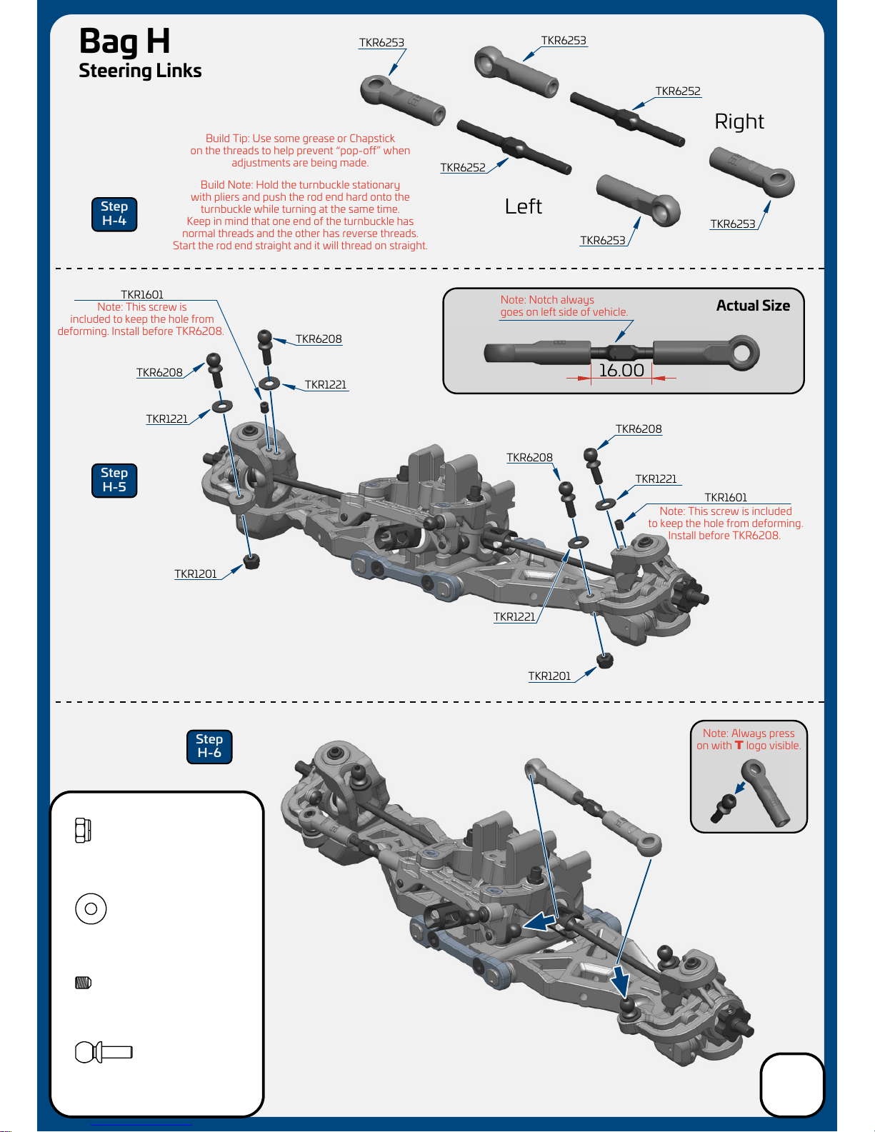
16.00
TKR1201
M3 Lock Nut Black
x2
TKR6252
TKR6253
Right
Left
TKR6253
TKR6253
TKR6208
TKR1221
TKR1221
TKR1201
TKR1201
TKR1601
TKR6208
TKR6252
TKR6253
TKR1601
TKR6208
TKR1221
TKR1221
TKR6208
TKR1221
M3x8mm Washer
x4
Note: Notch always
goes on
left side of vehicle.
Note: This screw is included
to keep the hole from deforming.
Install before TKR6208.
Note: This screw is
included to keep the hole from
deforming. Install before TKR6208.
Bag H
Steering Links
Step
H-4
Step
H-5
Step
H-6
TKR6208
M3x8mm Ball Stud
x4
x2
TKR1601
M3x4mm Set Screw
Actual Size
Note: Always press
on with
T
logo visible.
Build Note: Hold the turnbuckle stationary
with pliers and push the rod end hard onto the
turnbuckle while turning at the same time.
Keep in mind that one end of the turnbuckle has
normal threads and the other has reverse threads.
Start the rod end straight and it will thread on straight.
Build Tip: Use some grease or Chapstick
on the threads to help prevent “pop-o” when
adjustments are being made.
13

AB
WASHERS
Stock position is 1/A
13.50
TKR1201
M3 Lock Nut Black
x2
Note: Notch always
goes on
left side of vehicle.
Bag H
Front Camber Links
Step
H-7
Step
H-8
Step
H-9
Right
Left
TKR6252
TKR6253
Right
Left
TKR6253
TKR6208
TKR6664
TKR6252
TKR6253
TKR6208
TKR1201
TKR1403
TKR1405
TKR1403
M3x10mm Button Head Screw
x2
TKR1405
M3x14mm Button Head Screw
x2
TKR1405
M3x14mm Button Head Screw
x2
TKR6208
M3x8mm Ball Stud
x2
1
TKR6581
Note: These screws
only needs to be
snug. Do not
over-tighten.
Actual Size
*TKR6581C
(Option)
TKR6253
Note: Always press
on with
T
logo visible.
Build Note: Hold the turnbuckle stationary
with pliers and push the rod end hard onto the
turnbuckle while turning at the same time.
Keep in mind that one end of the turnbuckle has
normal threads and the other has reverse threads.
Start the rod end straight and it will thread on straight.
Build Tip: Use some grease or Chapstick
on the threads to help prevent “pop-o” when
adjustments are being made.
1
2
14

TKR1323
TKR6501
TKR6586
TKR1323
TKR1322
TKR1401
TKR6546
TKR1323
TKR1323
TKR6530
TKR6634
TKR6538
Step
I-1
Step
I-2
Step
I-3
TKR1322
M3x8mm Flat Head Screw
x2
TKR1401
M3x6mm Button Head Screw
x2
TKR1323
M3x10mm Flat Head Screw
x10
Thread
Lock
Thread
Lock
Bag I
Front/Center
Assembly
15
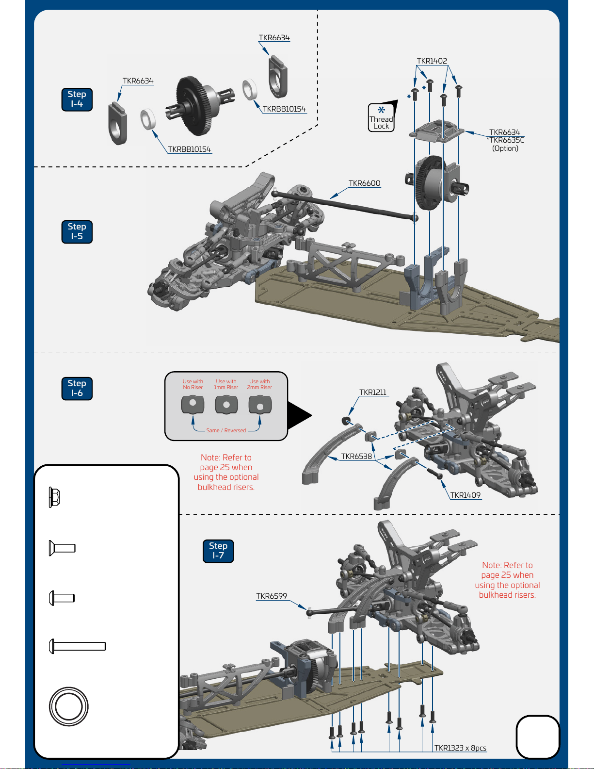
Same / Reversed
Use with
No Riser
Use with
1mm Riser
Use with
2mm Riser
Thread
Lock
Step
I-4
Step
I-5
Step
I-6
Step
I-7
TKR1402
TKR6634
TKR6634
TKR6600
TKR1211
TKR1409
TKR1323 x 8pcs
TKR6634
TKRBB10154
TKRBB10154
TKRBB101504
Ball Bearing(10x15x4mm)
x2
TKR1211
M3 Lock Nut Flange Black
x1
TKR1409
M3x20mm Button Head Screw
x1
TKR1323
M3x10mm Flat Head Screw
x8
TKR1402
M3x8mm Button Head Screw
x4 TKR6599
TKR6538
Note: Refer to
page 25 when
using the optional
bulkhead risers.
Note: Refer to
page 25 when
using the optional
bulkhead risers.
*TKR6635C
(Option)
Bag I
Center/Rear
Assembly
16
#500
shock oil
TKR1240
TKR1211
Note: Slot in spring
perch should face
outside of car.
Note: Black screw
is RH threaded.
It goes on the left
side of the car.
Silver screw is
LH threaded.
It goes on the right
side of the car.
TKR1211
TKR6712 TKR6527
Thread
Lock
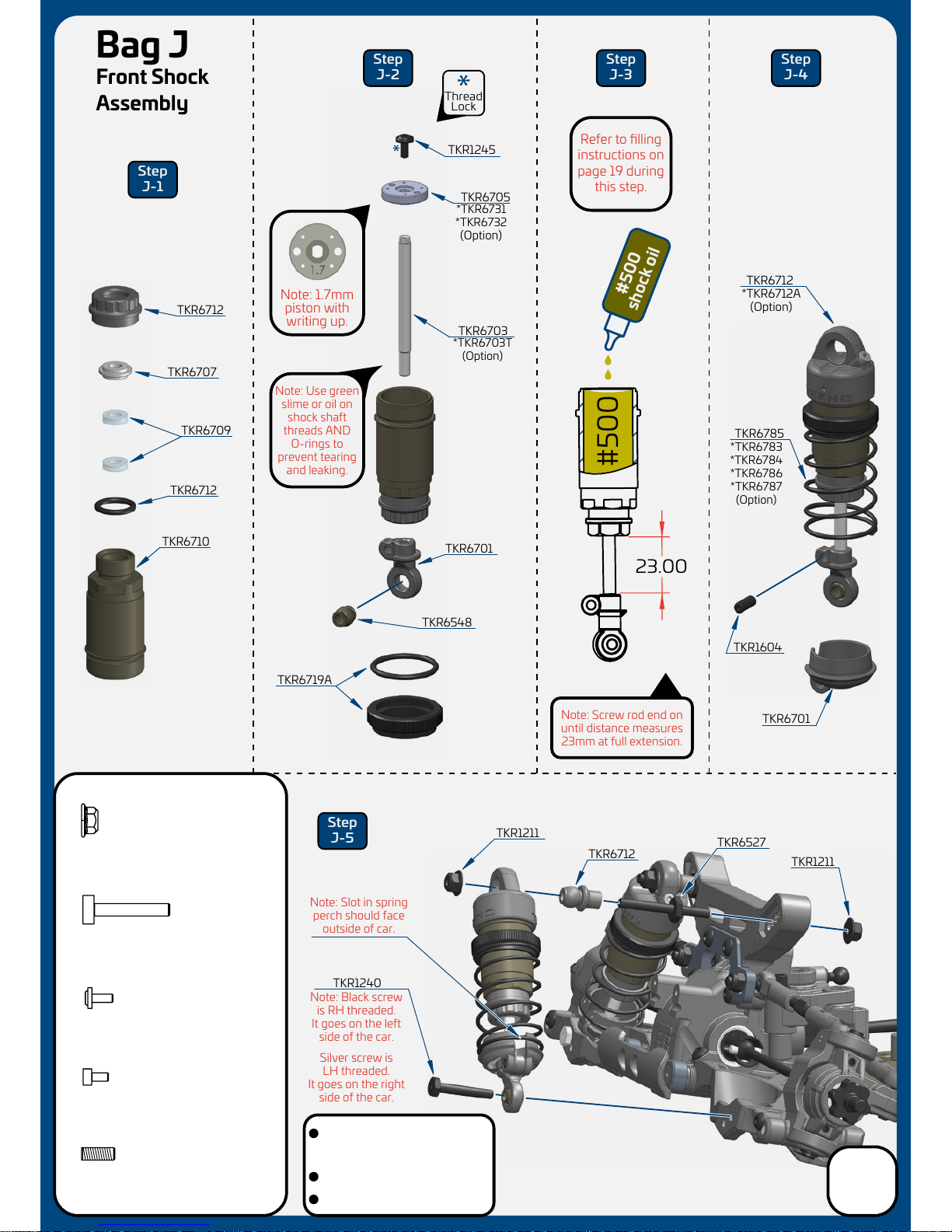
TKR6712
TKR6709
TKR6710
TKR6712
TKR6707
TKR1245
TKR6705
TKR6703
TKR6701
TKR6548
*TKR6703T
(Option)
*TKR6731
*TKR6732
(Option)
Note: Use green
slime or oil on
shock shaft
threads AND
O-rings to
prevent tearing
and leaking.
Note: Screw rod end on
until distance measures
23mm at full extension.
TKR1604
TKR6701
TKR6785
*TKR6783
*TKR6784
*TKR6786
*TKR6787
(Option)
TKR6712
*TKR6712A
(Option)
#500
Refer to filling
instructions on
page 19 during
this step.
Step
J-1
Step
J-2
Step
J-3
Step
J-4
Step
J-5
TKR1240
M3x18mm Shock Mnt Screw
x2
TKR1248
M2x4mm Emulsion Screw
x2
TKR1245
M2x5mm Piston Screw
x2
TKR1211
M3 Lock Nut Flange Black
x4
TKR1604
M3x8mm Set Screw
x2
23.00
TKR6719A
Note: 1.7mm
piston with
writing up.
Bag J
Front Shock
Assembly
17
Stock shock position is outside
hole on the arm and 2nd from
inside hole on the tower (2/B)
Stock front ride height is 18mm
Shock length (droop) is 78mm

TKR1240
TKR1211
Note: Slot in spring
perch should face
outside of car.
TKR1211 TKR6712
TKR6527
TKR6712
TKR6709
TKR6711
TKR6707
TKR1245
TKR6701
TKR6548 TKR1604
TKR6701
TKR6795
*TKR6793
*TKR6794
*TKR6796
*TKR6797
(Option)
TKR6712
*TKR6712A
(Option)
TKR6719A
Step
K-1
Step
K-2
Step
K-3
Step
K-4
Step
K-5
TKR1240
M3x18mm Shock Mnt Screw
x2
TKR1248
M2x4mm Emulsion Screw
x2
TKR1245
M2x5mm Piston Screw
x2
TKR1211
M3 Lock Nut Flange Black
x4
TKR1604
M3x8mm Set Screw
x2
#500
shock oil
Note: Screw rod end on
until distance measures
28mm at full extension.
#500
Refer to filling
instructions on
page 19 during
this step.
28.00
TKR6712
Note: Black screw
is RH threaded.
It goes on the right
side of the car.
Silver screw is
LH threaded.
It goes on the left
side of the car.
TKR6704
*TKR6704T
(Option)
TKR6705
Thread
Lock
Note: Use green
slime or oil on
shock shaft
threads AND
O-rings to
prevent tearing
and leaking.
*TKR6731
*TKR6732
(Option)
Note: 1.8mm
piston with
writing up.
Bag K
Rear Shock
Assembly
18
Stock shock position is outside
hole on the arm and 2nd from
inside hole on the tower (2/B)
Stock rear ride height is 21mm
Shock length (droop) is 88mm
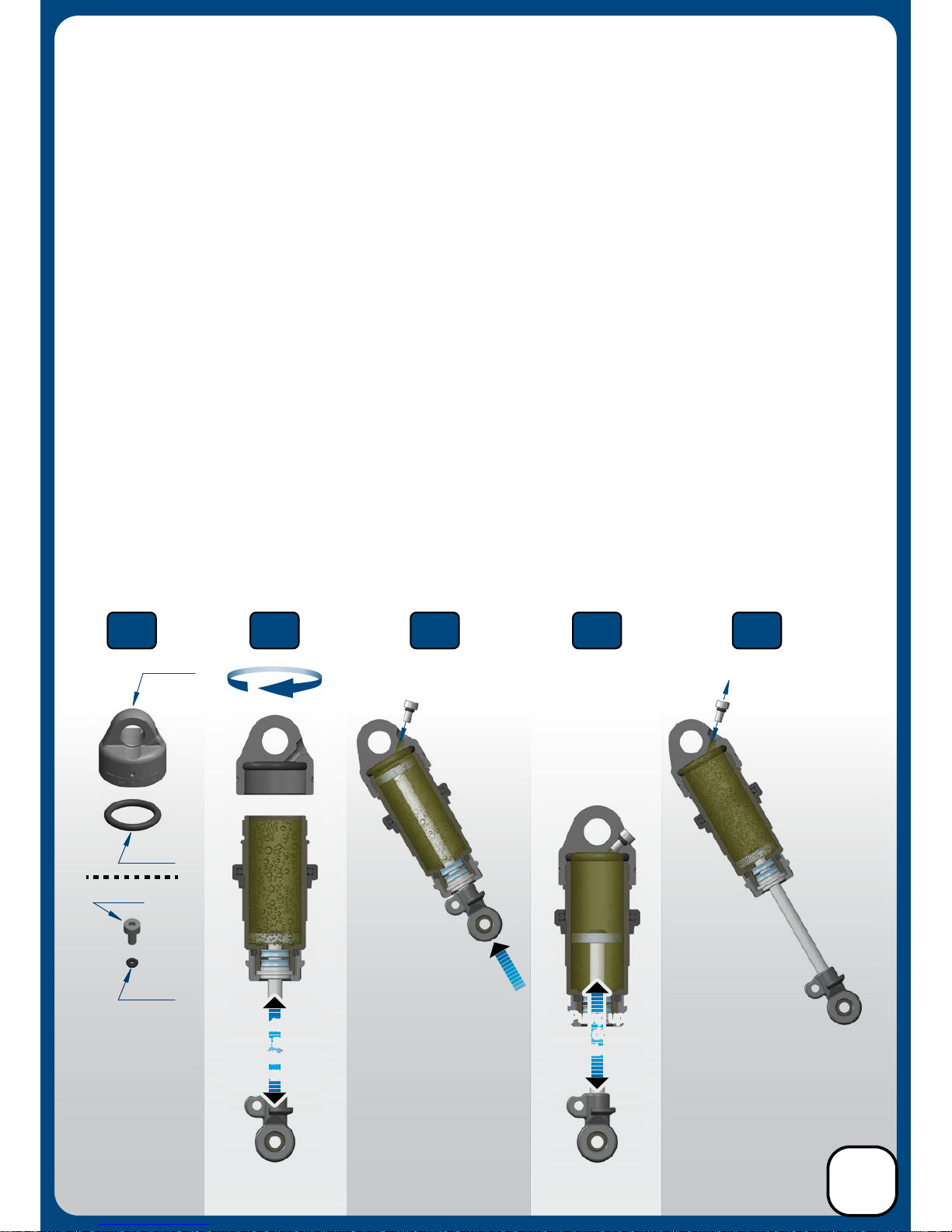
Shock Filling Instructions
For both front and rear shocks
Step 1. Insert all four larger o-rings into the emulsion caps (there may be a bit of flashing that
should be cleared around the bleeder hole as well) and set aside. Install the small o-rings onto the small
emulsion screws by placing the o-rings on a pit mat or towel and pressing the screws into the o-rings
(add 1 small drop of oil onto the seal to help make the screw slide in easier).
Step 2. Fill shock with oil all the way to the top and pump the shock shaft up and down 3-5 times.
Step 3. Screw on the cap all the way tight (shock tool TKR1115 is helpful for holding the shock body).
Be careful to not cross-thread the caps. Start by turning in the oposite direction before tightening.
Step 4. With the shock at about a 45° angle, push and hold the shock shaft to the top of the stroke and
insert the prepared emulsion screw/seal. Oil will leak out during this process. Tighten the screw until
snug (do not over-tighten). Wipe o excess oil before moving on to step 5.
Step 5. Pump the shock shaft up and down about 20 times vigorously. This emulsifies the oil.
Step 6. With the shock shaft fully extended, remove the emulsion screw from the cap to do the final bleed.
Step 7. With the shock at about a 45° angle, push and hold the shock shaft to the top and insert the
prepared emulsion screw/seal again. Oil will leak out during this process. Finish by tightening the screw
until snug (do not over-tighten).
We've found it's easiest to complete steps 1 & 2 on each shock before moving on to step 3.
By the time you've finished step 2 on the last shock, the first one will be ready for step 3.
Fill with oil,
Pump up and down
3-5 times,
Then screw on cap
Fill with oil,
Pump up and down
3-5 times,
Then screw on cap
Pump up
and down
30 times
Pump up
and down
20 times
Prepare caps by
inserting seals
AND
Push smaller
screws into small
o-rings
Push shaft up
to bleed air out
THEN
Insert screw snug
(do not over-tighten)
TKR6714
TKR6714
TKR6712
TKR1248
Pull shaft down,
remove screw
THEN
Push shaft up to bleed air,
insert screw snug
(do not over-tighten)
Step
1
Step
2-3
Step
4
Step
5
Step
6-7
19
TKR1321
M3x6mm Flat Head Screw
x2
TKR1323
M3x10mm Flat Head Screw
x6
TKR1221
M3X8mm Washer
x6
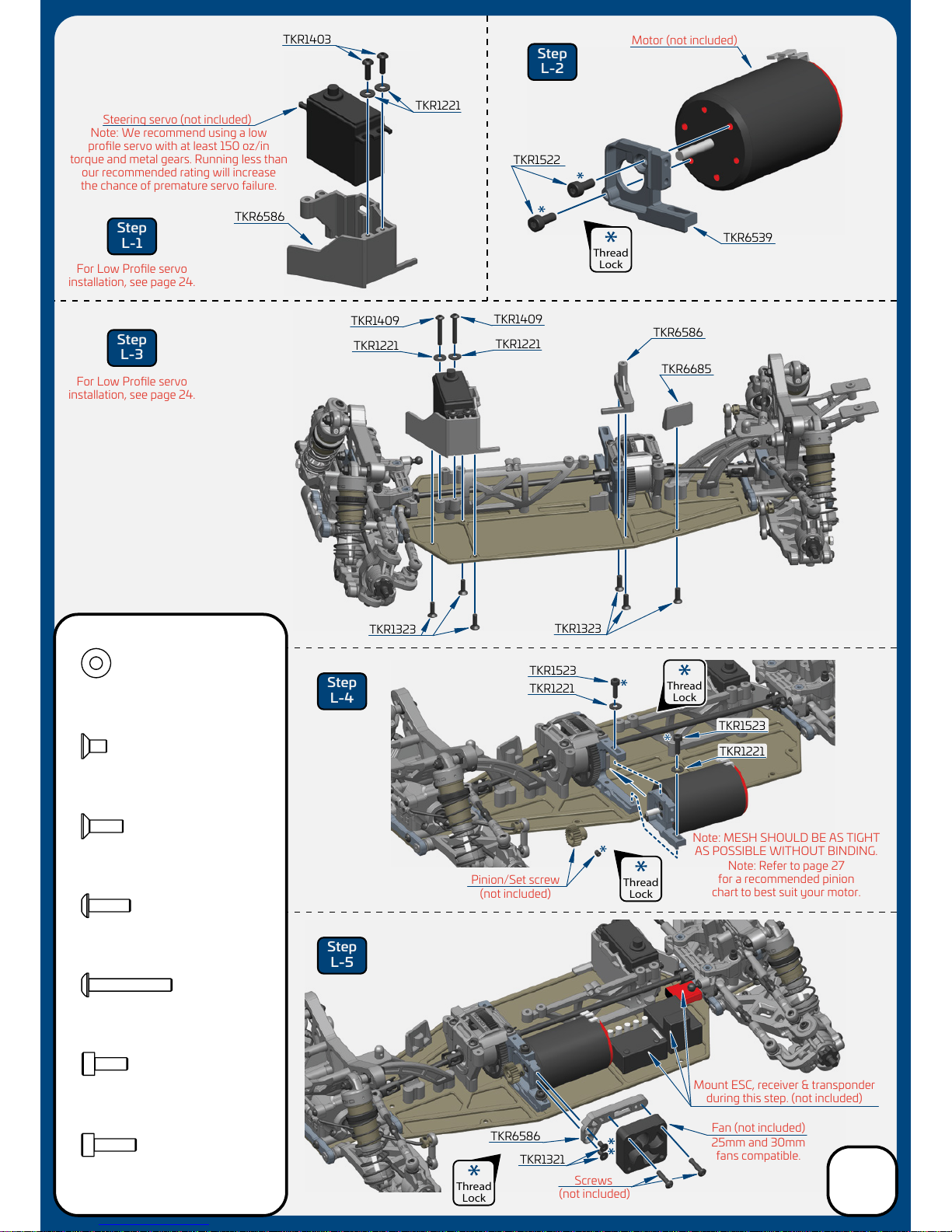
TKR1522
M3x8mm Cap Head Screw
x2
TKR1403
M3x10mm Button Head Screw
x2
TKR1409
M3x20mm Button Head Screw
x2
TKR1523
M3x10mm Cap Head Screw
x2
TKR1409
Steering servo (not included)
For Low Profile servo
installation, see page 24.
For Low Profile servo
installation, see page 24.
TKR1323 TKR1323
TKR1409
TKR1221 TKR6586
TKR6685
TKR1523
TKR1221
TKR1523
TKR1221
TKR1221
TKR1321
TKR6586
TKR6586
TKR6539
TKR1522
TKR1403
Screws
Note: Refer to page 27
for a recommended pinion
chart to best suit your motor.
Note: MESH SHOULD BE AS TIGHT
AS POSSIBLE WITHOUT BINDING.
Motor (not included)
Fan (not included)
(not included)
Pinion/Set screw
(not included)
25mm and 30mm
fans compatible.
Mount ESC, receiver & transponder
during this step. (not included)
Step
L-1
Step
L-3
Step
L-4
Step
L-5
Step
L-2
TKR1221
Thread
Lock
Thread
Lock
Thread
Lock
Thread
Lock
Note: We recommend using a low
profile servo with at least 150 oz/in
torque and metal gears. Running less than
our recommended rating will increase
the chance of premature servo failure.
Bag L
Final Assembly
20
Table of contents
Other Tekno Motorized Toy Car manuals

Popular Motorized Toy Car manuals by other brands


Traxxas
Traxxas Scale and Trail TRX 6 88096-4 owner's manual

New Age
New Age CRL-101 manual

Spinmaster
Spinmaster MECCANO EVOLUTION 2 IN 1 instructions

Schumacher
Schumacher BossCat instruction manual

Tamiya
Tamiya MITSUBISHI PAJERO METALTOP WIDE BLACK... Assembly

Mega Bloks
Mega Bloks Probuilder CARBON Series instructions


