TekPower TP-3005D User manual

1
CONTENTS:
1. SAFETY PRECAUTION AND PROCEDURES................................................................2
1.1 BEFORE USE..............................................................................................................................3
1.2 DURING USE...............................................................................................................................3
1.3 AFTER USE.................................................................................................................................3
2. GENERAL........................................................................................................................4
3. FEATURES AND SPECIFICATIONS...............................................................................4
3.1 OPERATION CONDITION...........................................................................................................4
3.2 TECHNICAL SPECIFICATION ....................................................................................................4
4. OPERATING INSTRUCTIONS........................................................................................5
4.1 INSTRUMENT DESCRIPTION.................................................................................................... 5
4.1.1 FRONT PANEL DESCRIPTION.......................................................................................5
4.1.2 REAR PANEL DESCRIPTION .........................................................................................6
5. POWER SUPPLY DESCRIPTION...................................................................................7
5.1 SETTING THE OUTPUT VOLTAGE............................................................................................ 7
5.2 SETTING THE OUTPUT CURRENT ........................................................................................... 8
5.3 CHANGING THE FUSE...............................................................................................................9
6. PACKAGE......................................................................................................................10
7. TROUBLESHOOTING...................................................................................................10

2
1. SAFETY PRECAUTION AND PROCEDURES
The instrument is designed and tested in accordance with EN publication EN60950-1:2006+A11:2009.
The instrument has been tested in accordance to the following EC Directives(EMC):
a. EN55022:2006+A1:2007
b. EN61000-3-2:2006+A1:2009+A2:2009
c. EN61000-3-3:2008
d. EN61000-4-2:2009
e. EN61000-4-3:2006+A1:2009
f. EN61000-4-4:2004
g. EN61000-4-5:2006
h. EN61000-4-6:2009
i. EN61000-4-11:2004
j. EN61000-6-1:2007
k. EN61000-6-3:2007
l. EN55024:1998+A1:2001+A2:2003
The instrument complies with the requirements of the European Council Directive 89/336/EEC (EMC
Directive) and 73/23/EEC (Low Voltage Directive). To ensure that the instrument is used safety, follow
all safety and operating instructions in this manual. If the instrument is not used as described in this
manual, the safety features might be impaired
WARNING
!
Non compliance with the warnings and/ or the instructions for use may
damage the instument and/or its components or injure the operator.
Take extreme care under the following conditions when using the instrument:
zFor your own safety and that of the instrument, you must follow the procedure described in this
instruction manual.
zDo not use this instrument in a location where there is explosive gas in the vicinity. The use of this
instrument in a location where there is explosive gas could result in explosion.
zIf there is any smoke, abnormal odor, or abnormal sound coming from this instrument, immediately
switch off the power and disconnect the power cord. Continuous using of this instument under
these conditions could result in electrical shock or fire. After disconnecting the power cord, contact
the service offices for repair. Repair by the user is dangerous and should be strictly avoided.
zTake care not to allow water to get into this insturment. The use of this instrument in a wet state
could result in electrical shock or fire. If water or other foreign matter has prenetrated this
instrrment, first switch the power off, remove the power cord and call for repair.
zDo not place this instrument on an unstable or slanting surface. The dropping or turning over this
instrument could result in electrical shock, injury or fire. If this instrument has been dropped or its
cover has damaged, switch the power off, remove the power cord and call for repair

3
zDo not allow any foreign matter such as metal or inflammable substance to get into the instrument
via the air holes. The penetration of any foreign matter from the ventilation holes could result in fire,
electrical shock, or power failure.
zUse this instrument with the rated AC power sources. Use of this instrument with a voltage other
than specified could result in electrical shock, fire or power failure. The usable power voltage range
is marked on the rear panel.
zDo not remove either the cover or panel.
zDo not modify this instrument.
zAvoid use of damaged cables.
1.1 BEFORE USE
1. Make sure the POWER switch is at the “0” position and connect the power cord to the power supply.
2. To set the constant voltage output: Push the POWER SWITCH to “I” position. Adjust the VOLTAGE
COARSE / CURRENT COARSE tune knob for roughly adjustment or VOLTAGE FINE / CURRENT
FINE tune knob for fine adjustment. Once the voltage or current value is reached, to desire value
appear on Display Panel.
1.2 DURING USE
1. Ensure the voltage and current set to zero, prevent a undesired output damage the circuit.
2. The supplied voltage should be within 110V AC or 220V AC±10% (60/50Hz) and the system is
capable for supplying the maximum power consumption as indicated on section 3.1.
3. Keep a distance at least greater than 10cm between the power supply and other things for airy
reason when usage. Do not place this power supply in a hot, dusty, wet, corrosive gas stage or near
the poison substance.
4. This power supply need warm up 30 minutes to meet the specification section 3.2.
5. Keep hands and face away from the heat sink.
6. Do not touch the heat sink during operation.
1.3 AFTER USE
1. Once the operation completed, remove all connection to the power supply, especially the power
source.
2. Wait the power cold down.
3. Store in a dry, well air and non-dusty environment.

4
2. GENERAL
TP3005DM is a high performance and precision DC regulated power supply. TP3005DM has constant
voltage mode, constant current mode, over-voltage protection function, overload protection, and 8 hours
continuous full load features. Voltage and current value can be adjusted linearly. With the extract
stability and enhanced responsibility, this power supply is suitable for bench, laboratory, university, high
school, and enterprise use or where needed a high performance and precision regulated DC power
supply.
3. FEATURES AND SPECIFICATIONS
3.1 OPERATION CONDITION
Input Voltage:110V AC or 220V AC±10% 60/50Hz
Power Consumption:300W
Operating Condition:Temperature:0~40℃
Relative Humidity*:90%RH
Storage Condition:Temperature:-20℃~80℃
Relative Humidity*:80%RH
*Non-condensing
3.2 TECHNICAL SPECIFICATION
Constant Voltage Mode (CV)
Voltage Range: 0~30V (main output), fixed 5V (USB output)
Line Effect: ≤1×10⁻⁴ +3mV (main output)
≤100mV (USB output)
Loading Effect:
≤1×10¯4+3mV (output current≤3A) (main output)
≤2×10¯4+3mV (3A≤output current≤5A) (main output)
≤100mV (USB output)
Noise and Ripple: 1mV (main output)
2mV (USB output)
Temperature Coefficient 150ppm/℃
Constant Current Mode (CC)
Current Range 0~5A (main output), Max. 2A (USB output)
Line Effect: ≤2×10⁻³ +3mA (main output)
Loading Effect: ≤1×10¯3+3mA (output current≤3A) (main output)
≤2×10¯3+3mA (3A≤output current≤5A) (main output)
Temperature Coefficient: 500ppm/℃
5
Display Accuracy
Digital Display: 3 Digits Display: ±0.5%+2d
Resume Time: Less than 100μs
Mechanical Specification
Weight(kg): 5.6
Dimension(mm): 130 (W) × 165 (H) × 320 (D)
4. OPERATING INSTRUCTIONS
4.1 INSTRUMENT DESCRIPTION
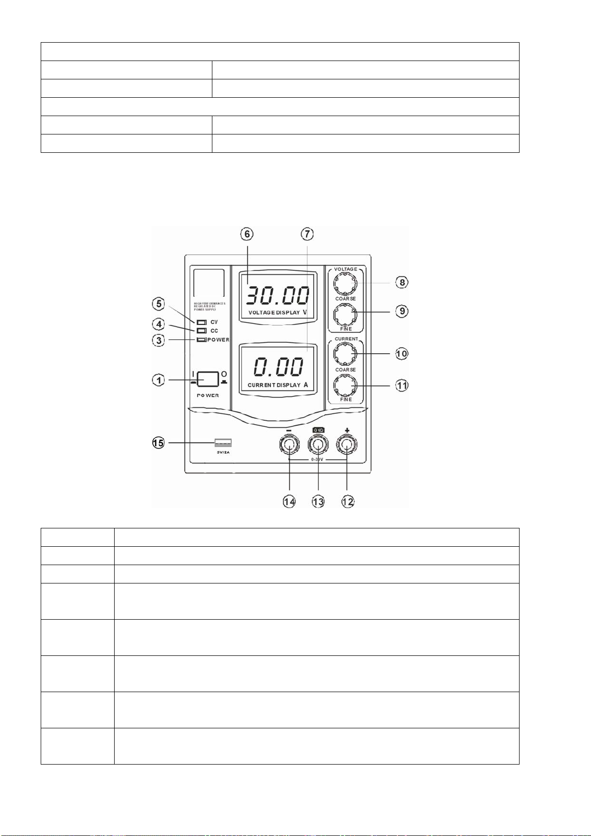
4.1.1 FRONT PANEL DESCRIPTION
Item Description
1 POWER SWITCH: Press it to power on the supply
3 POWER INDICATOR
4 CC (constant current mode) INDICATOR: When the power supply is at the constant
current mode, this LED light will be on.
5 CV (constant voltage mode) INDICATOR: When the power supply is at the constant
voltage mode, this LED light will be on.
6 Voltage Display Panel: This display will indicate the voltage value that will be applied
to the circuit.
7 Current Display Panel: This display will indicate the current value that will be applied to
the circuit
8 VOLTAGE COARSE (roughly adjustment) tune knob: Turn clockwise for increasing the
voltage value; turn anti-clockwise for decreasing the voltage value.
Other manuals for TP-3005D
1
Table of contents
Other TekPower Power Supply manuals


Popular Power Supply manuals by other brands

Videx
Videx 520MR Installation instruction

Poppstar
Poppstar 1008821 Instructions for use

TDK-Lambda
TDK-Lambda LZS-A1000-3 Installation, operation and maintenance manual

TDK-Lambda
TDK-Lambda 500A instruction manual

Calira
Calira EVS 17/07-DS/IU operating instructions

Monacor
Monacor PS-12CCD instruction manual


