Tektron 453A Service manual
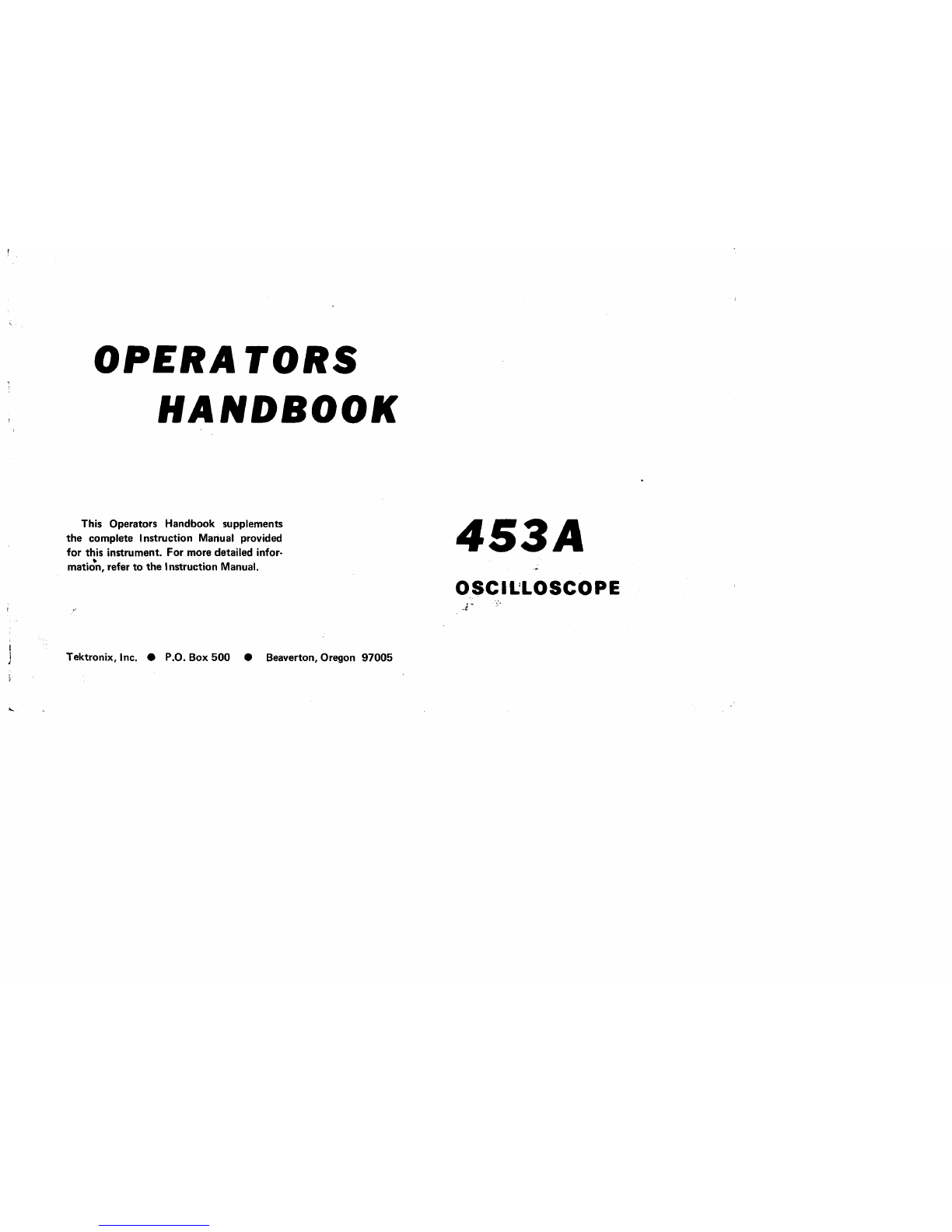
OPERATORS
HANDBOOK
This Operators Handbook supplements
the
complete Instruction Mariual provided
for this instrument. For more detailed infor-
mati;n,
refer
to
the
Instruction Manual.
Tektronix, Inc. •P.O. Box
500
•Beaverton, Oregon
97005
453A
OSCll:LOSCOPE
.r
453A
OPERATORS
HANDBOOK
CONTENTS
Specification
Operating Instructions
Operating Voltage
Controls and Connectors
Simplified Operation Instructions
Users Calibration
1
5
5
13
17
070·1105-00
Copyright ©1970
by
Tektronix, Inc., Beaverton,
Oregon. Printed
in
the
United States
of
America.
All
rights reserved. Contents
of
this publication may
not
be
reproduced
in
any
form
without
permission
of
the
copyright owner.
®1170

General
SPECIFICATIONS
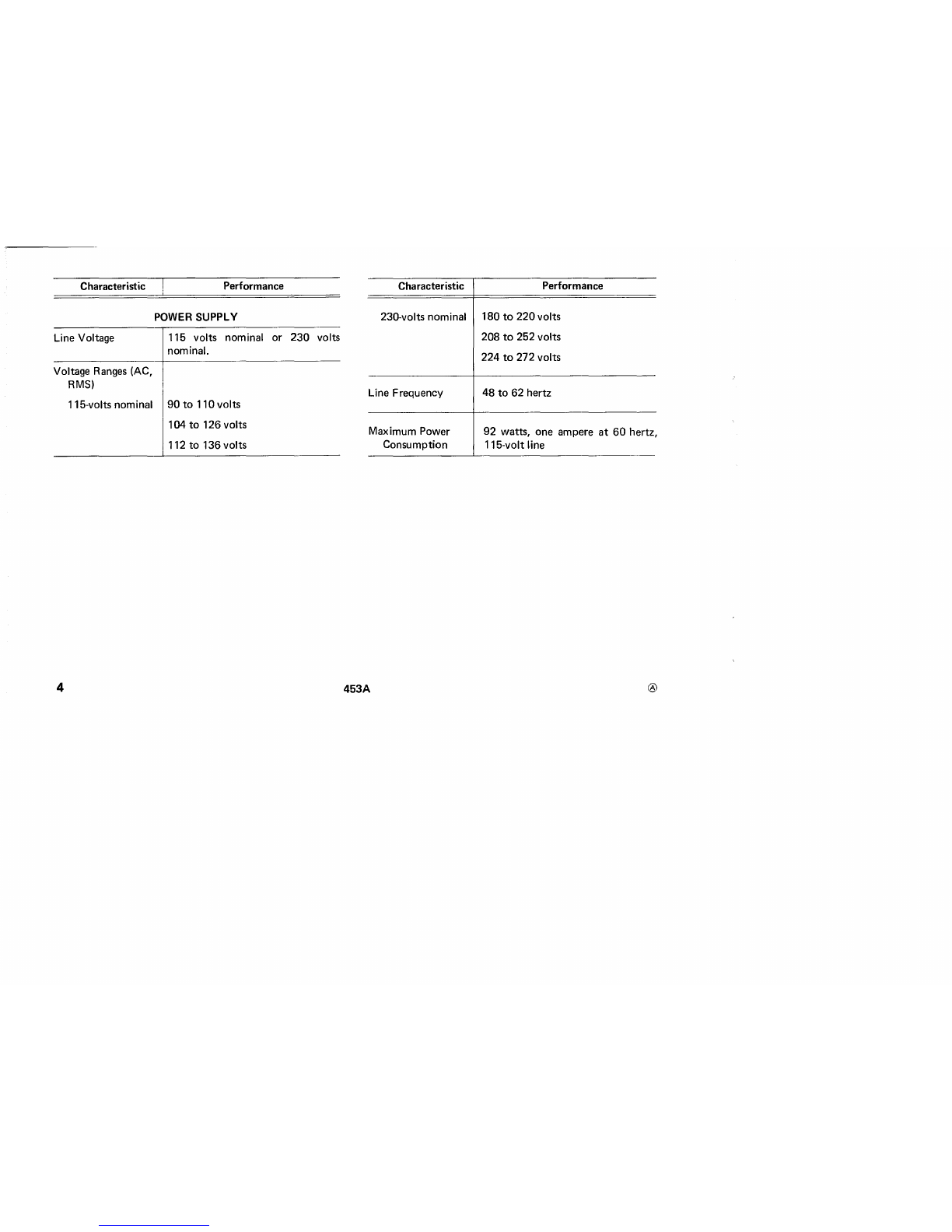
Characteristic Performance
VERTICAL DEFLECTION SYSTEM
The
specifications given
in
this
handbook
are only a
partial list condensed from
the
specifications listed
in
Sec-
tion 1
of
the
Instruction Manual. These specifications
most
directly reflect
the
capabilities
of
the
453A.
Characteristic Performance
AC
Low-Frequency
Response (lower
-3
dB point)
Without
probe
With P6061 Probe
1.6 hertz
or
less
at
all
deflection
factors.
0.16 hertz
or
less
at
all
deflection
factor~.
Deflection Accuracy Within 3%
of
indicated deflection.
Cascaded deflection factor uncali-
brated.
Maximum Safe
Input
Voltage
600
vorts
DC
+peak
AC
(one kilo-
hertz
or
less).
Internal Trigger
Sensitivity
Bandwidth
at
-3
dB
points (with
or
without
P6061
Probe)
20
mV
to
10
VOLTS!DIV
10 mV!DIV
5mV!DIV
Channels 1and 2
cascaded
@I
DC
to
at
least
60
megahertz.
DC
to
at
least
50
megahertz.
DC
to
at
least
40
megahertz.
DC
to
at
least
25
megahertz.
453A
AC
LF
REJ
TRIGGERING
(A
AND BSWEEP)
0.3
division
of
deflection, mini-
mum,
30
hertz to 10 megahertz;
in-
creasing
to
one division
at
60
mega-
hertz.
0.3 division
of
deflection, mini-
mum,
30
kilohertz
to
10 mega-
hertz; increasing
to
one division at
60
megahertz.
1
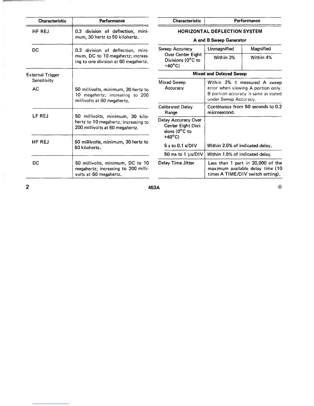
HORIZONTAL DEFLECTION SYSTEM
A
and
B
Sweep
Generator
50
ms
to
1lls/DIV Within 1.5%
of
indicated delay.
Sweep Accuracy Unmagnified Magnified
Over
Center
Eight
f-------+-------
Divisions
(DoC
to
Within
3%
Within
4%
+40
0
C)
Performance
Less
than
1
part
in
20,000
of
the
maximum
available delay
time
(10
times ATIME/DIV switch setting).
Continuous
from
50
seconds
to
0.2
microsecond.
Within
2%
±measured Asweep
error
when viewing A
portion
only.
B
portion
accuracy
is
same
as
stated
under
Sweep Accuracy.
Within 2.5%
of
indicated delay.
Mixed and Delayed Sweep
Characteristic ,
Mixed Sweep
Accuracy
Calibrated Delay
Range
Delay
Time
Jitter
Delay Accuracy Over
Center
Eight Divi-
sions
(DoC
to
+40
0C)
5 s
to
0.1 siDIV
Characteristic Performance
HF REJ
0.3
division
of
deflection,
..
mInI-
mum,
30
hertz
to
50
kilohertz.
DC
0.3
division
of
deflection, mini-
mum,
DC
to
10
megahertz; increas-
ing
to
one
division
at
60
megahertz.
External Trigger
Sensitivity
AC
50
millivolts, minimum,
30
hertz
to
10 megahertz; increasi
ng
to
200
millivolts
at
60
megahertz.
LF REJ
50
millivolts, minimum,
30
kilo-
hertz
to
10
megahertz; increasing
to
200
millivolts
at
60
megahertz.
HF REJ
50
millivolts, minimum,
30
hertz
to
50
kilohertz.
DC
50
millivolts, minimum,
DC
to
10
megahertz; increasing
to
200
milli-
volts
at
60
megahertz.
2
453A
®
Characteristic IPerformance Characteristic Performance
Phase difference be-
3°
or
less
at
50
kilohertz.
tween Xand Y
amplifiers
External Horizontal Amplifier
Input
to
CH
1OR X
Connector
Accuracy
(DoC
to
Within
5%
of
indicated deflection.
+40
0
C)
XBandwidth
at
Five megahertz
or
greater.
Upper
-3
dB
Point
Accuracy
(DoC
to
+40
0
C)
Voltage
Current
CALIBRATOR
±1%
±1%
Phase difference
3°
or
less
at
50
kilohertz.
between Xand
Yamplifiers
Input
to
EXT TRIG
OR XINPUT
Connector
Deflection
Factor
BSOU RCE switch
in
EXT;
270
milllivolts/division ±15%.
BSOU RCE switch
in
EXT
..;-
10;
2.7 volts/division ±20%.
XBandwidth
at
Five megahertz
or
greater.
Upper
-3
dB
point
Repetition Rate ±0.5%
Risetime One microsecond
or
less.
Output
Resistance Approximately
200
ohms
in
V
position.
Approximately
20
ohms in 0.1 V
position.
ZAXIS INPUT
Sensitivity Five volt peak-to-peak signal pro-
duces noticeable modulation
at
nor-
mal intensity.
Usable Frequency
DC
to
50
megahertz
or
greater.
Range
®
453A
3
Characteristic ]Performance Characteristic Performance
Line Voltage
POWER SUPPLY
115 volts nominal
or
230
volts
nominal.
23O-volts nominal 180
to
220
volts
208
to
252 volts
224
to
272 volts
Voltage Ranges (AC,
RMS)
115-volts nominal
90
to
110 volts
104
to
126 volts
112 to 136 volts
4
Line Frequency
Maximum Power
Consumption
453A
48
to
62 hertz
92 watts, one ampere
at
60
hertz,
115-volt line
®
OPERATING
INSTRUCTIONS
CONTROLS
AND
CONNECTORS
age line voltage
to
which
the
instrument
is
to
be connected.
Replace
the
cover and tighten
the
two captive screws.
Before applying power
to
the
instrument, check
that
the
indicating tabs on
the
switch bars are protruding through
the
correct
holes for
the
desired nominal line voltage and
regulating range.
Vertical (both channels
except
as
noted)
VOLTS/DIV Selects vertical deflection factor
(VAR control
must
be in calibrated
position for indicated deflection
factor).
OPERATING
VOLTAGE
~~
This
instrument
is
designed
for
operation
from
a
power
source
with
its
neutral
at
or
near earth
(ground)
potential
with
aseparate safety-earth con-
ductor.
It
is
not
intended
for
operation
from
two
phases
of
amultiphase system,
or
across the
legs
of
a
single-phase three-wire system.
The
453A
can be operated from
either
a115-volt
or
a
230-volt nominal line voltage source.
The
Line Voltage
Selector assembly on
the
rear panel converts this instru-
ment
from one operating voltage
to
the
other. This
assembly also includes
the
fuses
that
provide
protection
for
the
line-input portion
of
the
instrument.
To
convert from
115-volt to 230-volt nominal line voltage,
or
vice versa,
remove
the
cover from
the
Line Voltage Selector assembly.
Then, pull
out
the
Selector switch bar and plug it back
into
the
remaining holes. Change
the
line-cord power plug
to
match
the
power-source receptacle
or
use a115-
to
230-volt
adapter.
To
change regulating ranges, pull
out
the
Range
Selector switch bar, slide
it
to
the
desired position and plug
it back in. Select arange which
is
centered
about
the
aver-
Display
INTENSITY
FOCUS
BEAM
FINDER
Controls brightness
of
display.
Provides
adjustment
for well-defined
display.
Compresses display with
in
graticule
area,
independent
of
display posi-
tion
or
applied signals.
®
453A
5

STEP
ATTEN BAL
Vertical (cont)
VAR
UNCAL
POSITION
GAIN
Input
Coupling
(AC-GND-DC)
(Variable)
Provides
continuously
variable
deflection
factors
between
the
calibrated
settings
of
the
VOL
TS/DIV
switch.
(Uncalibrated) Light indicates
that
the
VAR
control
is
not
in
the
cali-
brated
position.
Controls
vertical position
of
trace.
Screwdriver
adjustment
to
set gain
of
the
Vertical System.
Selects
method
of
coupling
input
signal
to
Vertical Deflection Sys-
tem.
AC:
DC
component
of
input
signal
is
blocked.
Low
frequency
limit
(-3
dB
point)
is
about
1.6
hertz.
GND:
(Ground)
Input
circuit
is
grounded
(does
not
ground
applied signal).
DC: All
components
of
the
input
signal are passed
to
the
Vertical
Deflection
System.
CH
1OR X
and
CH
2OR Y
MODE
(Step
Attenuator
Balance) Screw-
driver
adjustment
to
balance
Input
Amplifier
in
the
5,
10,
and
20
mV
positions
of
the
VOL
TS/DIV
switch.
I
nput
connector
for
vertical signal.
Selects vertical
mode
of
operation.
CH
1:
The
Channel 1signal
is
dis-
played.
CH
2:
The
Channel 2signal
is
dis-
played.
AL
T:
(Alternate) Dual-trace display
of
signal
on
both
channels. Dis-
play switched
between
channels
at
end
of
each sweep.
CHOP:
(Chopped)
Dual-trace dis-
play
of
signal
on
both
channels.
Display
switched
between
chan-
nels
at
a
repetition
rate
of
about
500
kilohertz.
6
453A
®

Aand BTriggering (both where applicable)
LEVEL Selects
amplitude
point
on
trigger
signal
at
which sweep
is
triggered.
CH
1OR X·Y:
Sweep
circuits trig-
gered
only
from
the
signal
applied
to
the
CH
1OR X
con·
nector.
No signal available
at
CH
lOUT
connector.
CH
1lights,
located beside A
and
BSOU RCE
switches, indicate
that
the
I
NT
TRIG
switch
is
in
the
CH
1
OR
X·Y position.
For
X·Y
mode
operation,
Channel 1signal
is
con
nected
to
the
Horizontal COUPLI
NG
Amplifier.
INTTRIG
ADD:
Channell
and 2signals
are
algebraically added and
the
alge·
braic sum
is
displayed
on
the
CRT.
(Internal Trigger) Selects source
of
internal trigger signal from vertical
system. Also selects
the
source
of
the
Xsignal
for
X-Y
mode
oper·
ation.
NORM: Sweep
circuits
triggered
from displayed channel(s). Chan-
nel 1signal available
at
CH
1
OUT
connector.
INVERT
(CH
2only)
HF STAB
(A
Triggering Only)
SLOPE
Inverts
the
Channel 2display when
pulled
out.
(H igh
Frequency
Stability) De·
creases
display
jitter
for
high·
frequency trigger signals. Has negli·
gible
effect
at
lower repetition
rates.
Selects slope
of
trigger signal which
starts
the
sweep.
+: Sweep can be triggered from
positive-going
portion
of
trigger
signal.
-:
Sweep can be triggered from
negative·going
portion
of
trigger
signal.
Determines
method
of
coupling
trigger signal
to
trigger circuit.
®
453A
7
Aand BTriggering (cant)
AC: Rejects
DC
and
attenuates
sig-
nals below
about
30
hertz.
Ac-
cepts signals between
about
30
hertz and
60
megahertz.
LF
REJ: (Low Frequency Reject)
Rejects
DC
and
attenuates
sig-
nals below
about
30
kilohertz.
Accepts signals between
about
30
kilohertz and
60
megahertz.
when
the
light
is
off,
the
trigger
signal
is
obtained
from
the
dis-
played
channel(s). Source
of
internal trigger signal
is
selected
by
the
INT
TRIG
switch.
LINE: Trigger signal
obtained
from
asample
of
the
line voltage ap-
plied
to
this instrument.
EXT: Trigger signal
obtained
from
an external signal applied
to
the
EXT
TRIG
INPUT
connector.
SOURCE
HF REJ: (High Frequency Reject)
Accepts signals between
about
30
hertz and
50
kilohertz;
re-
jects DC and
attenuates
signals
outside
the
above range.
CH
1
DC:
Accepts all trigger signals from
DC
to
60
megahertz
or
greater.
Selects source
of
trigger signal.
INT: Internal trigger signal ob- EXT TRIG INPUT
tained from Vertical Deflection
System. When
CH
1light
is
on,
trigger signal
is
obtained
only
from
the
Channel 1
input
signal;
EXT
-;-
10:
Attenuates
external trig-
ger
signals approximately
10
times.
Light indicates
that
the
internal
trigger signal
is
obtained
only from
the
signal
connected
to
the
CH
1
OR X
connector
(see INT
TRIG
switch).
Input
connector
for
external trigger
signal.
Connector
for
BTriggering
also serves as external horizontal in-
put
for
the
Xsignal when
HO
RIZ
DISPLAY switch
is
in
X-Y
position
8
~A
®

A
and
B
Sweep
DELAY-TIME
MULTIPLIER
ASWEEP
TRIG'D
UNCAL A
OR
B
A
and
B
TIME/DIV
and
DELAY
TIME
®
and
BSOURCE
switch
is
in
EXT
position.
Provides variable
sweep
delay
be-
tween
0.20
and
10.20
times
the
de-
lay
time
indicated
by
the
ATI M
E/
DIV
switch.
Light
indicates
that
A
sweep
is
trig-
gered
and
will
produce
a
stable
dis-
play
with
correct
INTENSITY
and
POSITION
control
settings.
(Uncalibrated)
Light
indicates
that
either
the
AVAR
or
B
VARIABLE
control
is
not
in
the
calibrated
posi-
tion.
A
TIME/DIV
switch
(clear
plastic
flange)
selects
the
sweep
rate
of
the
A
sweep
circuit
for
A
sweep
only
operation
and
selects
the
basic de-
lay
time
(to
be
multiplied
by
DELAY-TIME
MULTIPLIER
dial
setting)
for
delayed
or
mixed
sweep
operation.
B
TIME/DIV
(DE-
LAYED
SWEEP)
switch
selects
453A
AVAR
BSWEEP MODE
sweep
rate
of
Bsweep
circuit
for
delayed
or
mixed
sweep
operation
only.
Variable
controls
must
be
in
calibrated
positions
for
calibrated
sweep
rates.
(Variable) Provides
continuously
variable A
sweep
rate
between
the
calibrated
settings
selected
by
the
A
TIME/DIV
switch.
A
sweep
rate
is
calibrated
when
control
is
set
fully
clockwise
to
cal ibrated.
Selects
B
sweep
operation
mode.
TRIGGERABLE
AFTER
DELAY
TIME:
B
sweep
circuit
will
not
produce
a
sweep
until
atrigger
pulse
is
received
following
the
delay
time
selected
by
the
DE-
LAY
TIME
(A
TIME/DIV)
switch
and
the
DELAY-TIME
MULTIPLIER
dial.
B
STARTS
AFTER
DELAY
TIME:
B
sweep
circuit
runs
immedi-
ately
following
delay
time
selec-
ted
by
the
DELAY
TIME
switch
9

A
and
B
Sweep
(cant)
determined
by
8SWEEP MODE
switch.
HORIZ DISPLAY
10
and
DELAY-TIME
MULTI-
PLI
ER
dial.
Selects
horizontal
mode
of
opera-
tion.
A: Horizontal deflection provided
by Asweep. 8
sweepinoper-
ative.
AINTEN DURING
8:
Sweep
rate
determined
by A
TIME/DIV
switch. An intensified
portion
appears
on
the
display during
the
8sweep time.
This
switch
position provides a
check
of
the
duration
and
position
of
8
sweep (delayed sweep) with
re-
spect
to
the
delaying sweep (A).
8(DELAYED SWEEP):
Sweep
rate
determined
by 8TIME/DIV
switch
with
the
delay
time
deter-
mined
by
the
setting
of
the
DE-
LAY
TIME
(A
TIME/DIV)
switch and
the
DELAY-TIME
MULTIPLIER dial.
Sweep
mode
MAG
ASWEEP MODE
453A
MIXED:
80th
time
bases are oper-
ating.
The
sweep rate
of
the
first
part
of
the
sweep
is
determined
by
the
A
TIME/DIV
switch;
the
last
part
is
determined
by
the
8
TIME/DIV switch.
The
amount
of
display allocated
to
each
time
base
is
determined
by
the
setting
of
the
DELAY-TIME MULTI-
PLIER dial.
X-Y: Horizontal
deflection
pro-
vided
by
an
external
signal.
(Magnifier) Increases sweep
rate
to
ten
times
setting
of
the
A
or
8
TIME/DIV
switch
by
horizontally
expanding
the
center
division
of
the
display. Light indicates
when
mag-
nifier
is
on
(magnifier inoperative in
X-Y
mode).
Determines
the
operating
mode
for
Asweep.
®
'1<
i
1
®
AUTO
TRIG:
(Automatic
Trigger)
Sweep
Initiated
by
the
applied
trigger signal
at
point
selected
by
the
ALEVEL
control
when
the
trigger signal
repetition
rate
is
above
about
20
hertz
and
within
the
frequency
range selected
by
the
A
COUPLING
switch. Trig-
gered sweep can
be
obtained
only
over
the
amplitude
range
of
the
applied trigger signal. When
the
ALEVEL
control
is
outside
the
amplitude
range,
the
trigger
repetition
rate
is
below
the
lower
frequency
limit (or
above
upper
limit
for
HF
REJ),
or
the
trigger signal
is
inadequate,
the
sweep
free
runs
at
the
sweep
rate
selected
by
the
TIME!DIV
switch
to
produce
a
bright
refer-
ence
trace.
NORM
TRIG:
(Normal Trigger)
Sweep
initiated
by
the
applied
trigger signal
at
point
selected
by
the
A
LEVEL
control
over
the
frequency
range selected
by
the
ACOUPLING
switch.
Triggered
sweep
can
be
obtained
only
over
the
amplitude
range
of
the
453A
RESET
ASWEEP LENGTH
applied trigger signal. When
the
ALEVEL
control
is
outside
the
amplitude
range,
the
trigger
repetition
rate
is
outside
the
fre-
quency
range selected
by
the
A
COUPLING
switch,
or
the
trig-
ger signal
is
inadequate,
there
is
no
trace.
SINGLE
SWEEP:
After
asweep
is
displayed,
further
sweeps
cannot
be
presented
until
the
RESET
button
is
pressed. Display
is
trig-
gered as
for
NORM
operation
using
the
ATriggering
controls.
When
the
RESET
button
is
pressed
(SINGLE SWEEP
mode),
asingle
display will
be
presented (with cor-
rect
triggering)
when
the
next
trig-
ger pulse
is
received.
RESET
light
(inside
RESET
button)
remains
on
until atrigger
is
received and
the
sweep
is
completed.
RESET
button
must
be
pressed again before an-
other
sweep
can be displayed.
Adjusts
length
of
Asweep. In
the
FU
LL position (clockwise
detent),
11

A
and
B
Sweep
(cant)
Switch:
Controls
power
to
the
instrument.
POSITION
FINE
1
kHz
CAL
POWER ON
12
the
sweep
is
at
least
10
divisions
long. As
this
control
is
rotated
counterclockwise,
the
length
of
A
sweep
is
reduced
until it
is
less
than
four
divisions long
just
before
the
detent
in
the
fully-counterclock-
wise
position
is
reached.
In
the
B
ENDS Aposition
(counterclock-
wise
detent).
the
A
sweep
is
reset
at
the
end
of
the
Bsweep
to
provide
the
fastest possible
sweep
repetition
rate
for
delayed
sweep displays.
Controls
horizontal
position
of
trace.
Provides
more
precise
horizontal
position
adjustment.
(One-kilohertz
calibrator) Cali-
brator
output
connector.
Light:
Indicates
that
POWER
switch
is
on
and
the
instrument
is
connected
to
aline voltage
source.
Side
Panel
ASTIG
BTIME!DIV
VARIABLE
PROBE LOOP
AGATE
B
GATE
453A
(Astigmatism)
Screwdriver
adjust-
ment
used
in
conjunction
with
the
FOCUS
control
to
obtain
awell-
defined
display. Does
not
require
re-adjustment
in
normal
use.
Provides
continuously
variable B
sweep
rate
between
the
calibrated
settings
of
the
B
TIME!DIV
switch.
B
sweep
rate
is
cal
ibrated
when
control
is
set
fully
clockwise
to
CAL.
Current
loop
providing
five-
mill
i
ampere
square-wave
current
from
calibrator
circuit.
Output
connector
providing arec-
tangular
12
volt
pulse
coincident
with
A
Sweep.
Output
connector
providing arec-
tangular
12
volt
pu
Ise
coincident
with
B
Sweep.
®

CH
lOUT
(Channell
Output)
Output
connec-
tor
providing asample
of
the
signal
applied
to
the
CH
1OR Xconnec-
tor
when the
INT
TRIG
switch
is
in
the
NORM
position.
CALIBRATOR
Switch selects
output
voltage
of
Calibrator. One-volt
and
O.l-volt
square wave available.
TRACE
ROTATION
Screwdriver
adjustment
to
align
trace
with
horizontal graticule lines.
Rear
Panel
Z
AXIS
INPUT I
nput
connector
for
intensity mod-
ulation
of
the
CRT
display.
Line Voltage Selector Switching assembly
to
select
the
nominal operating voltage
and
the
line voltage range. The assembly
also includes the line fuses.
Voltage Selector: Selects nominal
operating voltage range (115 V
or
230
V).
Range Selector: Selects line voltage
range
(low,
medium, high).
GENERAL
OPERATING
INFORMATION
Simplified Operating Instructions
General. The
following
operating instructions
will
allow
calibrated measurements in most applications. The operator
should
be
familiar
with
the
complete
function
and oper-
ation
of
the
instrument
as
described in the complete
453A
I
nstruction
Manual before using this procedure.
Normal Sweep Display
1. Set I
NTENSITY
control
fully
counterclockwise.
2.
Set
Input
Coupling switches
to
AC,
VAR
VOLTS/
DIV
controls
to
calibrated, and vertical MODE switch
to
CH
1
(use
AL
Tor CHOP
for
dual-trace display).
3.
Push
ASWEEP
MODE,
ASLOPE, A
COUPLING,
and
ASOURCE switches
to
the up position.
4. Set A
TIME/DIV
switch
to
1
ms/DIV,
A
VAR
control
to
calibrated and
HORIZ
DISPLAY
switch
to
A.
5. Set POWER switch
to
ON.
Allow
several minutes
warmup.
®453A 13
6.
Connect
signal
to
the
CH
1
OR
X
connector.
7.
Advance
INTENSITY
control
until display
is
visible
(if display
is
not
visible
with
INTENSITY
control
at
mid-
range, press BEAM
FINDER
switch
and
adjust
VOL
TS/DIV
switch
until display
is
reduced
in
size vertically;
then
center
compressed
display
with
vertical
and
horizontal
POSITION
controls;
release BEAM
FINDER
switch).
Set
FOCUS
con-
trol
for
well-defined display.
8.
Set
VOL
TS/DIV
switch
and
vertical
POSITION
con-
trol
for
display
which
remains
within
display
area
vertically.
9.
Set
ALEVEL
control
for
stable
display.
10.
Set
A
TIME/DIV
switch
and
horizontal
POSITION
control
for
display
which
remains
within
the
display area
horizontally.
11.
To
make
a
peak-to-peak
voltage
measurement,
use
the
following
procedure:
a.
Turn
the
vertical POSITION
control
so
the
lower
portion
of
the
waveform
coincides
with
one
of
the
grati-
cule
lines
below
the
center
horizontal
line,
and
the
top
of
the
waveform
is
within
the
viewing area. Move
the
display
with
the
horizontal
POSITION
control
so
one
of
the
peaks lies
near
the
center
vertical line.
b. Measure
the
divisions
of
vertical
deflection
from
peak
to
peak.
Make sure
the
VAR
VOL
TS/DIV
control
is
in
the
calibrated
position.
12.
To
measure
the
time
between
two
points
on
awave-
form,
use
the
following
procedure:
a.
Set
the
A
TIME/DIV
switch
to
the
fastest
sweep
rate
that
displays
less
than
eight
divisions
between
the
time
measurement
points.
b.
Adjust
the
vertical POSITION
control
to
move
the
points,
between
which
the
time
measurement
is
made,
to
the
center
horizontal
graticule
line.
c.
Adjust
the
horizontal
POSITION
control
to
center
the
display
within
the
center
eight
divisions
of
the
grati-
cule.
d.
Measure
the
horizontal
distance
between
the
time
measurement
points.
Be
sure
the
A V
AR
control
is
set
to
the
calibrated
position.
e. Multiply
the
distance
measured in
step
d
by
the
setting
of
the
TIME/DIV
switch.
14
453A
®

Magnified Sweep Display
1. Follow steps 1 - 10
for
Normal Sweep Display.
2. Adjust horizontal POSITION control
to
move
area
to
be
magnified
within
center division
of
CRT.
If
necessary,
change
TIME/DIV
switch setting
so
complete
area
to
be
magnified
is
within
center division.
3. Set
MAG
switch
to
X10
and
adjust horizontal
FINE
control
for
precise positioning
of
magnified display.
Delayed Sweep Display
1.
Follow steps 1 - 10
for
Normal Sweep Display.
2.
Set
B
SWEEP
MODE switch
to
BSTARTS
AFTER
DELAY
TIME,
HORIZ
DISPLAY
switch
to
A
INTEN
DURING B,
and
A
SWEEP
LENGTH control
to
FULL.
3. Pull
out
DELAYED
SWEEP
(B
TIME/DIV)
switch
and
turn clockwise
so
intensified zone on display
is
desired
length (intensified zone
will
be
displayed in delayed
form).
If
intensified zone
is
not
visible, change
INTENSITY
con-
trol setting.
4. Adjust
DELAY-TIME
MULTIPLIER
dial
to
position
intensified zone
to
portion
of
display
to
be
delayed.
5. Set
HORIZ
DISPLAY
switch
to
B
(DELAYED
SWEEP). Delayed sweep rate
is
shown
by
dot
on DE-
LAYED
SWEEP
(B
TIME/DIV)
switch.
6.
For
delayed display
with
less
jitter,
set
B
SWEEP
MODE switch
to
TRIGGERABLE
AFTER
DELAY
TIME,
all BTriggering switches up,
and
adjust B
LEVEL
control
for
stable display.
Mixed Sweep Display
1.
Follow
steps
1 - 10
for
Normal Sweep Display.
2. Set the B
SWEEP
MODE switch
to
BSTARTS
AFTER
DELAY
TIME,
HORIZ
DISPLAY
switch
to
MIXED,
and
A
SWEEP
LENGTH to
FULL.
3. Pull
out
DELAYED
SWEEP
(B
TIME/DIV)
switch
and
turn
clockwise
to
obtain the amount
of
magnification
desired.
®
453A
15
4. Adjust
DELAY-TIME
MULTIPLIER
dial to vary the
amount
of
delay time before the start
of
the magnified
portion
of
the display.
5. For mixed
sweep
display
with
less
jitter,
set B
SWEEP
MODE switch
to
TRIGGERABLE
AFTER
DELAY
TIME,
all BTriggering switches up,
and
adjust B
LEV
EL control
for
stable display.
X-Y
Display
1.
Set
INTENSITY
control
fully
counterclockwise.
2.
Set
both
Input
Coupling switches
to
AC
and
VAR
VO L
TS/DIV
controls
to
calibrated.
3. Set
INT
TRIG
switch
to
CH
1OR X-Y and
HORIZ
DISPLAY
switch
to
X-Yo
4.
Set
POWER switch
to
ON.
Allow
several
minutes
warmup.
5. Connect X(horizontal) signal
to
CH
1
OR
Xconnec-
tor
and
Y(vertical) signal
to
CH
2OR Yconnector.
6.
Advance
INTENSITY
control
until
display
is
visible
(if
display
is
not
visible,
press
BEAM
FINDER
switch and
adjust
CH
1and
CH
2
VOL
TS/DIV
switches
until
display
is
reduced in
size
both vertically
and
horizontally;
then center
compressed display
with
CH
1
and
CH
2POSITION con-
trols;
release
BEAM
FINDER
switch).
Set
FOCUS control
for
well-defined display.
7. Set
CH
1
and
CH
2VOLTS/DIV
switches
and
POSI-
TION
controls
for
display which remains
within
display
area.
CH
1controls affect horizontal deflection
and
CH
2
controls affect vertical deflection.
16 453A
USER'S
CALIBRATION
General
The
following
procedure
provides
calibration
infor-
mation
for
external
adjustments
of
the
453A.
See
the
com-
plete
Instruction
Manual
for
detailed
calibration
instruc-
tions.
Astigmatism
Obtain
a
display
of
the
calibrator
waveform.
Adjust
ASTIG
in
conjunction
with
the
FOCUS
control
for
the
best
definition
of
the
square-wave
display.
Trace Rotation
Obtain
a
free-running
trace.
Adjust
TRACE
ROTATION
so
the
trace
aligns
with
the
horizontal
lines
of
the
graticule.
Vertical Gain
Connect
the
.1
volt
calibrator
signal
to
the
input
connec-
tor
of
either
vertical
input
channel.
Set
the
vertical
MODE
switch
to
display
that
channel
and
set
that
channel's
deflec-
tion
factor
to
20
mV/DIV.
Adjust
the
front-panel
GAIN
adjustment
of
the
channel
for
exactly
5divisions
of
deflec-
tion.
The
best
measurement
accuracy
when
using
probes
is
provided
if
the
GAl N
adjustment
is
made
with
the
probes
installed.
Connect
the
one-volt
calibrator
signal
to
the
probe
tip.
Step Attenuator Balance
Set
both
Input
Coupling
switches
to
GND
and
obtain
a
free-running
alternate
dual-trace
display.
Adjust
the
STEP
ATTEN
BAL
control
in
each
input
channel
for
no
trace
shift
when
switching
the
appropriate
attenuator
switch
between
the
5, 10,
and
20
mV/div
positions.
XGain Check
(X-
YOperation)
Set
the
HORIZ
DISPLAY
switch
to
X-Y
and
the
INT
TRIG
switch
to
CH 1
OR
X-Yo
Set
the
CH 1
attenuator
switch
to
20
mV/div
and
the
CH 1
Input
Coupling
switch
to
DC.
Apply
the
.1
volt
calibrator
signal
to
the
CH 1
OR
X
connector.
Check
for
exactly
five divisions
of
horizontal
deflection
between
the
displayed
dots.
®
453A
17

Timing
Check
Connect
the
calibrator
signal
to
the
input
of
either verti-
cal channel and
set
the
vertical
MODE
switch
to
display
this
channel.
Set
the
HORIZ
DISPLAY switch
to
display
either
time
base.
Adjust
the
appropriate
triggering
controls
for a
triggered
display
at
a
sweep
rate
of
one
millisecond/
division. Check
the
display for
one
complete
cycle
of
the
calibrator
waveform for each
horizontal
division.
For
more
precise
timing
check,
refer
to
the
calibration
procedure
given
in
the
complete
I
nstruction
Manual.
18
453A
®
Table of contents


