EXFO FIP-400B User manual

User Guide
Fiber Inspection Probe and
ConnectorMax2 Mobile (iOS)
FIP-400B

ii FIP-400B
Copyright © 2016–2017 EXFO Inc. All rights reserved. No part of this
publication may be reproduced, stored in a retrieval system or transmitted
in any form, be it electronically, mechanically, or by any other means such
as photocopying, recording or otherwise, without the prior written
permission of EXFO Inc. (EXFO).
Information provided by EXFO is believed to be accurate and reliable.
However, no responsibility is assumed by EXFO for its use nor for any
infringements of patents or other rights of third parties that may result from
its use. No license is granted by implication or otherwise under any patent
rights of EXFO.
EXFO’s Commerce And Government Entities (CAGE) code under the North
Atlantic Treaty Organization (NATO) is 0L8C3.
The information contained in this publication is subject to change without
notice.
Trademarks
EXFO’s trademarks have been identified as such. However, the presence
or absence of such identification does not affect the legal status of any
trademark.
Units of Measurement
Units of measurement in this publication conform to SI standards and
practices.
Patents
Feature(s) of this product is/are protected by one or more of: US design
patent D751434 and equivalents in other countries.
Version number: 15.0.1.1

Contents
Fiber Inspection Probe iii
Contents
Certification Information ........................................................................................................v
1 Introducing the FIP-400B Fiber Inspection Probe and
ConnectorMax2 Mobile ................................................................................ 1
Probe ......................................................................................................................................2
Available Models ....................................................................................................................5
Probe Tips ...............................................................................................................................6
LED Indicators .........................................................................................................................6
ConnectorMax2 Mobile Software ..........................................................................................9
Technical Specifications .........................................................................................................10
Conventions ..........................................................................................................................11
2 Safety Information ..................................................................................... 13
Other Safety Symbols on Your Unit .......................................................................................15
Electrical Safety Information .................................................................................................16
3 Setting up Your Fiber Inspection Probe and ConnectorMax2 Mobile ..... 19
Preparing to Use the Mobile Application ..............................................................................19
Connecting or Disconnecting the Wireless Probe ..................................................................20
Changing the Fiber Inspection Probe Tip ..............................................................................23
Changing the FIP Nozzle (MF-Ready Probes Only) .................................................................24
Adjusting Brightness .............................................................................................................30
Setting up Identification .......................................................................................................32
Setting up the Incrementation ..............................................................................................34
Setting up Autonaming ........................................................................................................37
Setting up Auto Capture .......................................................................................................40
Managing and Selecting Test Configurations ........................................................................42
Modifying the File Format .....................................................................................................53
Stopping the Analysis Process on First Fail ............................................................................55
Restoring to Default Settings ................................................................................................57

Contents
iv FIP-400B
4 Inspecting Fiber Ends .................................................................................59
Inspecting Fiber Ends (Single Fiber and Transceiver - Fiber Receptacles) ..............................59
Inspecting Multiple Fiber Ends (MF-Ready Probes Only) .......................................................65
Saving Files ...........................................................................................................................75
Managing Files ....................................................................................................................78
Analyzing Captures ...............................................................................................................83
Creating and Viewing Reports ..............................................................................................89
Transferring Results With Third-Party Applications ................................................................93
Transferring Results Directly With Your Smart Device ............................................................99
Updating the Firmware .......................................................................................................100
5 Maintenance ..............................................................................................101
General Maintenance ..........................................................................................................101
Cleaning Lenses ..................................................................................................................102
Recycling and Disposal .......................................................................................................102
Recharging the Battery (FIP-425B and FIP-435 Models Only) ..............................................103
Replacing the Battery (FIP-425B and FIP-435 Models Only) .................................................104
6 Troubleshooting ........................................................................................107
Solving Common Problems .................................................................................................107
Changing the File Contents ................................................................................................110
Contacting the Technical Support Group ............................................................................112
Viewing Information About ConnectorMax2 Mobile .........................................................113
Viewing Online Help ...........................................................................................................114
Transportation ....................................................................................................................115
7 Warranty ....................................................................................................117
General Information ...........................................................................................................117
Liability ...............................................................................................................................118
Exclusions ...........................................................................................................................118
Certification ........................................................................................................................118
Service and Repairs .............................................................................................................119
EXFO Service Centers Worldwide ........................................................................................120
A Fiber Inspection Probe Tip Compatibility Chart .....................................121
Index ...............................................................................................................125

Certification Information
Fiber Inspection Probe v
Certification Information
North America Regulatory Statement
This unit was certified by an agency approved in both Canada and the
United States of America. It has been evaluated according to applicable
North American approved standards for product safety for use in Canada
and the United States.
Electronic test and measurement equipment is exempt from FCC part 15,
subpart B compliance in the United States of America and from ICES-003
compliance in Canada. However, EXFO Inc. makes reasonable efforts to
ensure compliance to the applicable standards.
The limits set by these standards are designed to provide reasonable
protection against harmful interference when the equipment is operated in
a commercial environment. This equipment generates, uses, and can
radiate radio frequency energy and, if not installed and used in accordance
with the user guide, may cause harmful interference to radio
communications. Operation of this equipment in a residential area is likely
to cause harmful interference in which case the user will be required to
correct the interference at his own expense.
Modifications not expressly approved by the manufacturer could void the
user's authority to operate the equipment.

Certification Information
vi FIP-400B
The wireless probe comes with an internal wireless module and antenna
for which the following information applies:
This equipment has been tested and found to comply with the limits
for a Class A digital device, pursuant to Part 15 of the FCC Rules.
This device complies with Industry Canada license-exempt RSS
standard(s). Operation is subject to the following two conditions: (1)
This device may not cause harmful interference, and (2) this device
must accept any interference received, including interference that may
cause undesired operation.
This device complies with the US/Canada portable RF exposure limit
set forth for an uncontrolled environment and is safe for intended
operation as described in this user documentation. The further RF
exposure reduction can be achieved if the device can be kept as far as
possible from the user’s body.
This device does not contain any user-serviceable components. Any
unauthorized product changes or modifications will invalidate
warranty and all applicable regulatory certifications and approvals.

Certification Information
Fiber Inspection Probe vii
European Community Declaration of Conformity
Warning: This is a class A product. In a domestic environment, this product
may cause radio interference in which case the user may be required to
take adequate measures.
Hereby, EXFO declares that the radio equipment type “Wideband Data
Transmission” is in compliance with European Directive 2014/53/EU.
The full text of the EU declaration of conformity is available at the following
Internet address: www.exfo.com/library.
The information about the Wi-Fi frequency bands is as follows:
Between the frequencies 2400.0 MHz - 2483.5 MHz.
The maximum output power is 15 dBm.
This device is a 2.4 GHz wideband transmission system (transceiver),
intended for use in all EU member states and EFTA countries, except in
France and Italy where restrictive use applies.
In Italy, the end-user should apply for a license at the national spectrum
authorities in order to obtain authorization to use the device for setting up
outdoor radio links and/or for supplying access to telecommunications
and/or network services.
This device may not be used for setting up radio links in France, and in
some areas the RF output power may be limited to 10 mW EIRP in the
frequency range of 2454 - 2483.5 MHz. For detailed information, the
end-user should contact the national spectrum authority in France.
Certification Information
viii FIP-400B
Japanese Technical Conformity Mark for Radio
Law
Technical parameters:
Standards: IEEE 802.11b/g/n
Operation Frequency: 2412 ~ 2483.5 MHz
Throughput: 150 Mbps, 1T1R
R018-160052

Fiber Inspection Probe 1
1 Introducing the FIP-400B Fiber
Inspection Probe and
ConnectorMax2 Mobile
The FIP-400B Fiber Inspection Probe is a portable video microscope used
to inspect fiber ends. Unlike traditional microscopes, the FIP-400B
facilitates the examination of patchcord connectors and also hard-to-reach
connectors on the back of patch panels and bulkhead adapters.
There are two different types of probes:
USB-wired probes, that are connected to platforms
wireless probes, that can be connected with a Wi-Fi or USB connection
to platforms or with a Wi-Fi connection to a mobile smart device
(Android or iOS)
standard wireless probes can inspect single fibers and transceivers
MF-Ready probes can inspect single fibers, transceivers and
multifiber connectors (mobile smart devices only)
Note: The appearance and the orientation (portrait or landscape) of the
application may vary depending on the smart device used.

Introducing the FIP-400B Fiber Inspection Probe and ConnectorMax2 Mobile
2FIP-400B
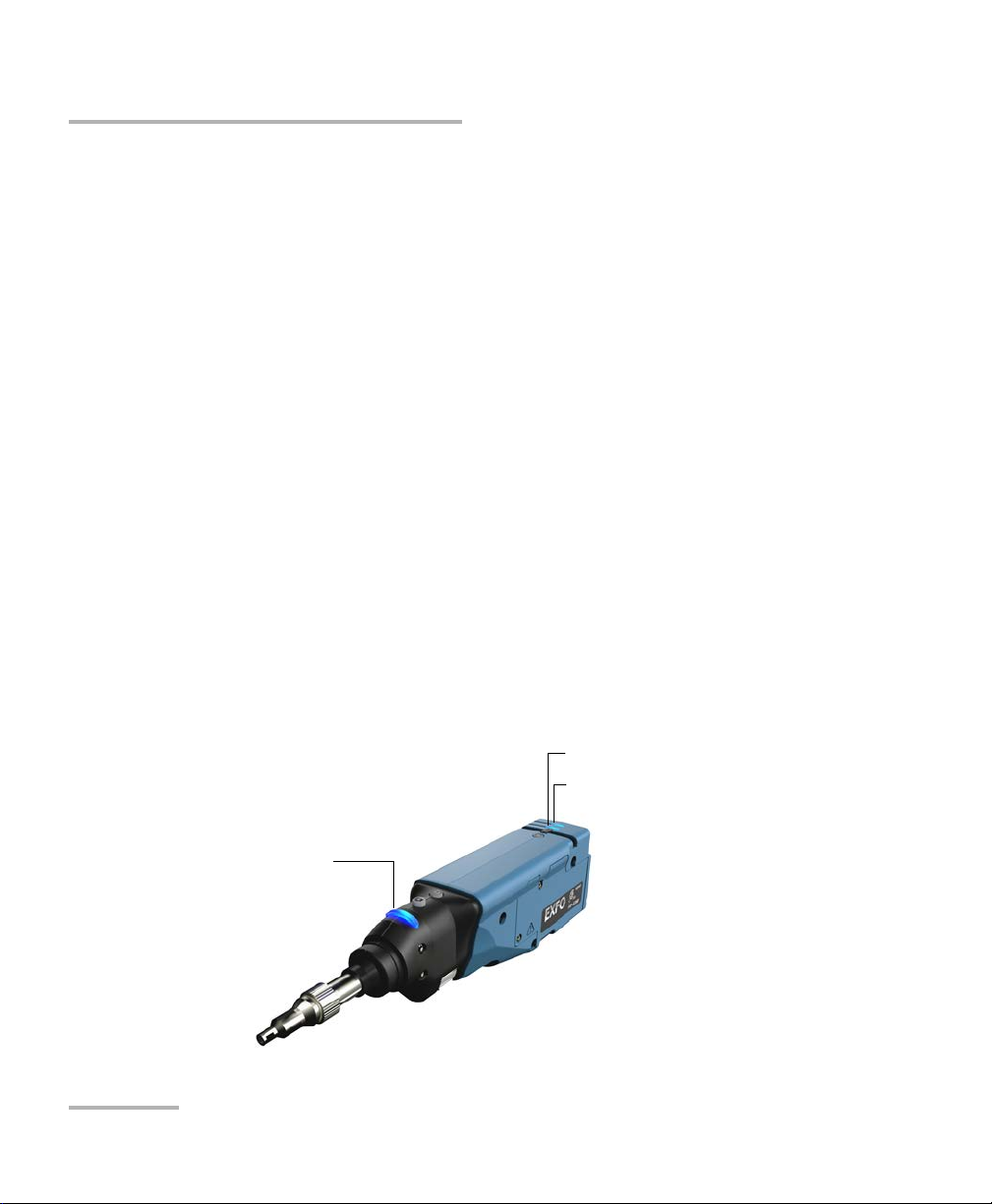
Probe
Probe
The FIP-400B is designed to be an intuitive, easy-to-use piece of
equipment. This video microscope is used for inspecting fiber ends.
Status LED
Retaining nut
Focus
Magnification control
Capture control
Interchangeable adapter
tips
Micro USB adapter connector
Battery compartment door
Battery LED
Wi-Fi LED

Introducing the FIP-400B Fiber Inspection Probe and ConnectorMax2 Mobile
Fiber Inspection Probe 3
Probe
The focus knob can be turned in either direction to focus the image.
The magnification control button allows you to shift between three
levels of magnification. When pressed for one second, it activates the
auto focus.
The capture control button allows you to capture an image, perform an
analysis, or return to the Live Video mode.
The retaining nut holds tips securely in place, ensuring they are always
fastened in the correct position.
The status LED gives you information about the probe or the analysis
results. See LED Indicators on page 6 for details.
Status LED
Retaining nut
Focus
Magnification control
Capture control
Micro USB adapter
connector
Battery compartment door
Battery LED
Wi-Fi LED
Inspection tip
Removable nozzle
Retaining nut
Trigger
MF-Ready probe with
inspection tip and
removable nozzle

Introducing the FIP-400B Fiber Inspection Probe and ConnectorMax2 Mobile
4FIP-400B
Probe
The battery LED indicates the charge status of the probe. See LED
Indicators on page 6 for details.
The Wi-Fi LED gives you information about the transmission process.
See LED Indicators on page 6 for details.
The interchangeable adapter tips give you the possibility to use various
tips depending on the type of connector you are inspecting. See
Changing the Fiber Inspection Probe Tip on page 23 for details.
Removable nozzles can be used with MF-Ready probes to inspect
multifiber dense panels. See Changing the FIP Nozzle (MF-Ready
Probes Only) on page 24 for details.
The micro USB adapter connector recharges the battery of the probe
when it is low. You can recharge the battery with the provided USB
cable and the adapter/charger that you connect to a power outlet. You
can also use the provided USB cable alone that you connect to a USB
port of a computer. See Recharging the Battery (FIP-425B and FIP-435
Models Only) on page 103 for details.
When the probe is connected to a power outlet or to a USB port, it still
works via Wi-Fi.
The battery compartment door is for battery replacement. See
Replacing the Battery (FIP-425B and FIP-435 Models Only) on page 104
for details.
The trigger allows you to inspect single-row or dual-row multifiber
connectors.
The design of the inspection tip enables you to connect any of the
interchangeable nozzles.
The probe comes equipped with a protective cap that fits over basic tips;
therefore, you do not need to remove the tip before putting the cap on.

Introducing the FIP-400B Fiber Inspection Probe and ConnectorMax2 Mobile
Fiber Inspection Probe 5
Available Models
Available Models
The features available for your probe are automatically detected when you
connect it to your smart device. The table below shows which feature is
available for each model.
Note: When the internal temperature of the FIP-435B is too low, the probe
performs a warmup that can last up to a minute.
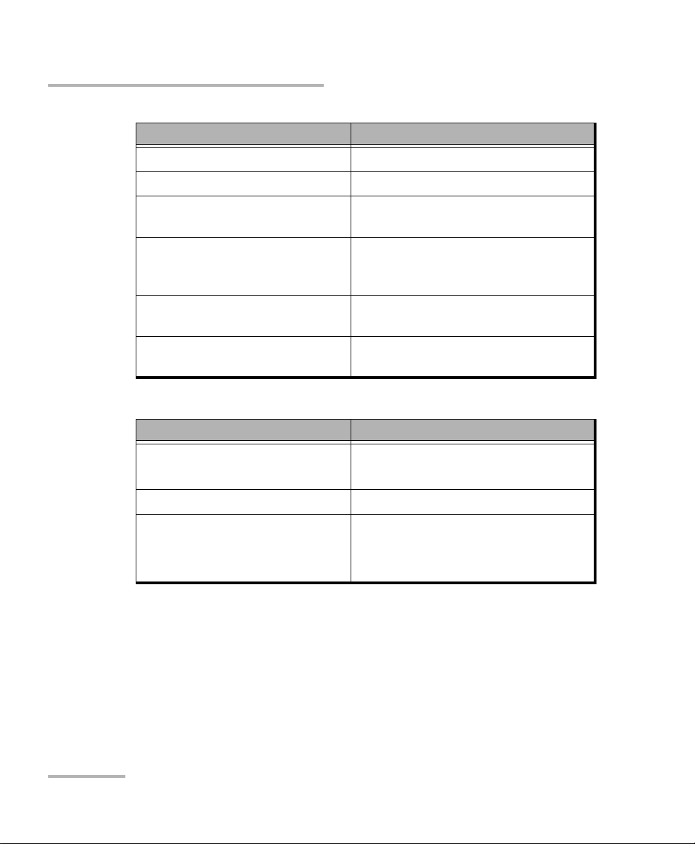
Models Inspection Auto
analysis
Auto
centering
Auto
focus
Auto
capture Wireless
FIP-425B X X X - - X
FIP-425B MF-Ready X X Xa
a. This feature is available when testing single fibers and transceivers. It is disabled when multifiber
connectors are inspected.
--X
FIP-435B X X X X X X
FIP-435B MF-Ready X X XaXX
aX
Introducing the FIP-400B Fiber Inspection Probe and ConnectorMax2 Mobile
6FIP-400B
Probe Tips
Probe Tips
The FIP-400B comes with two interchangeable tips included in two
different packages (UPC or APC). Additional models are also available.
UPC package:
FIPT-400-FC-SC: FC-SC Bulkhead tip
FIPT-400-U25M: Universal patchcord tip (2.5 mm ferrule)
APC package:
FIPT-400-SC-APC: SC APC tip for bulkhead adapter
FIPT-400-U25MA: Universal patchcord tip for 2.5 mm ferrules
Other tip models are available for various bulkhead adapters and
patchcord connectors. For more information about tips and their use, see
the Fiber Inspection Probe Tip Compatibility Chart on page 121, or visit the
EXFO Web site.
LED Indicators
The LEDs located on the probe give you information about the probe or the
analysis results.
Status LED
Battery LED
Wi-Fi LED

Introducing the FIP-400B Fiber Inspection Probe and ConnectorMax2 Mobile
Fiber Inspection Probe 7
LED Indicators
Status LED Meaning
Flashing blue Processing data
Flashing red There is a problem with the probe.
Follow the instructions on screen.
The auto focus is in timeout
There is an analysis error
Blue The probe is ready and operational
Red When the probe is connected,
indicates that the status of the
displayed measurement is Fail.
Note: Indicates the status of
the file selected in the
Measurements window.
Green When the probe is connected,
indicates that the status of the
displayed measurement is Pass.
Note: Indicates the status of
the file selected in the
Measurements window.
Introducing the FIP-400B Fiber Inspection Probe and ConnectorMax2 Mobile
8FIP-400B
LED Indicators
Battery LED Meaning
Flashing blue USB connected, battery charging
Blue USB connected, battery fully charged
Red Battery error (only visible when
connected to a USB cable)
Flashing yellow USB connected, battery not charging
because its temperature does not
allow the charging process
Yellow USB not connected, critical battery
level
Not lit USB not connected, battery above low
level
Wi-Fi LED Meaning
Blue Ready to transmit
Wireless transmission in progress
Red Transmission error
Not lit Probe is off
OR
Probe is initializing

Introducing the FIP-400B Fiber Inspection Probe and ConnectorMax2 Mobile
Fiber Inspection Probe 9
ConnectorMax2 Mobile Software
ConnectorMax2 Mobile Software
ConnectorMax2 Mobile is the application used to view the fiber
inspections. You can also use specific test configurations and analyze the
fibers automatically upon capturing a picture.
Battery status
Name of the file resulting
from the autonaming
User
preferences
Focus indicator
To disconnect the probe
To mak e a c a ptu r e
FIP-425B and FIP-435B,
except MF-Ready
probes testing
multifiber connectors

Introducing the FIP-400B Fiber Inspection Probe and ConnectorMax2 Mobile
10 FIP-400B
Technical Specifications
Technical Specifications
To obtain this product’s technical specifications, visit the EXFO Web site at
www.exfo.com.
Battery status
Name of the file resulting
from the autonaming
User
preferences
Focus indicator
To disconnect the probe
To mak e a c a pt u r e
FIP-425B and FIP-435B
MF-Ready probes
testing multifiber
connectors
Icons indicating the order
to follow to perform the 3
captures. The icons on
screen must match the
icons on the movable part
of the inspection tip.

Introducing the FIP-400B Fiber Inspection Probe and ConnectorMax2 Mobile
Fiber Inspection Probe 11
Conventions
Conventions
Before using the product described in this guide, you should understand
the following conventions:
WARNING
Indicates a potentially hazardous situation which, if not avoided,
could result in death or serious injury. Do not proceed unless you
understand and meet the required conditions.
CAUTION
Indicates a potentially hazardous situation which, if not avoided,
may result in minor or moderate injury. Do not proceed unless you
understand and meet the required conditions.
CAUTION
Indicates a potentially hazardous situation which, if not avoided,
may result in component damage. Do not proceed unless you
understand and meet the required conditions.
IMPORTANT
Refers to information about this product you should not overlook.

Other manuals for FIP-400B
3
Table of contents
Other EXFO Test Equipment manuals

EXFO
EXFO RTU-2 User manual

EXFO
EXFO FTB-200 User manual

EXFO
EXFO FTB-800 Series User manual

EXFO
EXFO Power Blazer User manual

EXFO
EXFO FTB-860 User manual

EXFO
EXFO Power Blazer User manual

EXFO
EXFO FTV-700 series User manual

EXFO
EXFO AXS-200/635i User manual

EXFO
EXFO FVA-600 User manual

EXFO
EXFO FIP-400 User manual

EXFO
EXFO AXS-200/850 User manual

EXFO
EXFO BRT-320A User manual

EXFO
EXFO MaxTester series Operation and maintenance manual

EXFO
EXFO LTB Series User manual

EXFO
EXFO Fiber Guardian FG-750 User manual

EXFO
EXFO ConnectorMax MFS-12 User manual

EXFO
EXFO AXS-200/635 User manual

EXFO
EXFO FTB-8500 Series User manual

EXFO
EXFO FTB-85100G User manual

EXFO
EXFO EX1 User manual


