Hella Gutmann BMA-Tool User manual

.
HBBMA_BV0001EN0816S0
460 988-04 / 08.16
User Manual en
BMA/BMB-Tool
Original User Manual

Ta le of contents BMA/BMB-Tool
Table of contents
1 Safety precautions ......................................................................... 4
1.1 General safety precautions............................................................4
1.2 Safety precautions for the BMA/BMB Tool .....................................5
1.3 Danger notices brake fluid..........................................................6
1.4 Safety precautions high voltage and line voltage.........................7
1.5 Safety precautions risk of injury .................................................7
2 Tool description...............................................................................8
2.1 Delivery contents ..........................................................................8
2.2 Intended use .................................................................................9
2.3 Tool description ..........................................................................10
3 Assembly of the BMB Tool.........................................................14
3.1 Assembling the BMB Tool............................................................14
4 Initial start-up................................................................................15
4.1 Preconditions..............................................................................15
4.2 Preparing the BMA/BMB Tool......................................................15
5 Working with the BMA/BMB Tool............................................17
5.1 Adjusting the working pressure ..................................................17
5.2 Brake systems with brake pressure regulator .............................17
5.3 Changing the brake fluid/bleeding the hydraulic system ..............18
5.4 Checking the wheel brake cylinders for free movement...............20
5.5 Replacing the brake fluid container .............................................21
5.6 Bleeding the BMA/BMB Tool .......................................................22
6 General information.....................................................................23
2

BMA/BMB-Tool Ta le of contents
6.1 Problem solutions .......................................................................23
6.2 Care and maintenance.................................................................23
6.3 Disposal......................................................................................24
6.4 Technical data of the BMA/BMB Tool ...........................................25
3

Safety precautions BMA/BMB-Tool
General safety precautions
1 Safety precautions
1.1 General safety precautions
• The BMA/BMB Tool ( rake maintenance tool) is for use
on motor vehicles only. It is a precondition for the use of
the BMA/BMB Tool that the user has knowledge of
automotive technology and is therefore aware of the
sources of danger and risks in the repair shop and on
motor vehicles.
• Please read the entire operating instructions carefully
efore using the BMA/BMB Tool.
• All notes given in the individual sections of this user
manual apply. The steps and safety precautions stated
elow must also e followed.
• Furthermore, please pay attention to all general
instructions from la our inspectorates, trade associations
and vehicle manufacturers as well as all laws, legal
ordinances and instructions that must e o served y a
repair shop.
4

BMA/BMB-Tool Safety precautions
Safety precautions for the BMA/BMB Tool
1.2 Safety precautions for the BMA/BMB Tool
In order to avoid incorrect handling and injury to the user or
destruction of the BMA/BMB Tool arising from this, pay
attention to the following:
• Always store these operating instructions together with
the BMA/BMB Tool.
• The BMA/BMB Tool must only e sold together with the
latest operating instructions.
• As part of their training, trainees may only operate the
BMA/BMB Tool under the supervision of an experienced
person.
• Protect the BMA/BMB Tool from frost and damp.
• Make connections to the vehicle only when the engine is
not running.
• Protect the BMA/BMB Tool from liquids like water, oil or
fuel (it is not waterproof).
• Protect the BMA/BMB Tool from heavy shock impact (do
not drop or knock over).
• Protect the BMA/BMB Tool and connection lines from hot
parts.
• Before relocation, repairs or work on the BMA/BMB Tool
that is not related to its operation: switch off the BMA/
BMB Tool and remove the power plug.
• In the event of danger, switch off the main switch and
remove the power plug.
• The BMA/BMB Tool is not designed for use with synthetic
rake fluid.
• Do not connect the BMA/BMB Tool to compressed air
using the quick coupling (17).
• Do not clean the BMA/BMB Tool using flamma le liquids.
• The BMA/BMB Tool must e transported and shipped
without rake fluid.
• Do not operate the BMA/BMB Tool without rake fluid.
• Do not fill or operate the BMA/BMB Tool with DOT 5
rake fluid (not suita le).
5

Safety precautions BMA/BMB-Tool
Danger notices – rake fluid
• Do not fill or operate the BMA/BMB Tool with liquids
containing mineral oil.
1.3 Dan er notices – brake fluid
O serve the following when handling rake fluid:
• Irritating to skin, eyes and respiratory system.
• In the event of contact with the eyes or skin, rinse
immediately with plenty of clean water.
• Seek medical attention immediately if rake fluid comes
into contact with the eyes or is swallowed.
• Use protective clothes, protective gloves and protective
goggles.
• Brake systems may e under (high) pressure.
• Always use suita le and compati le rake fluid. Follow
the instructions of the vehicle manufacturer.
• Never mix DOT 3, DOT 4 or DOT 5.1 (glycol- ased) rake
fluid with DOT 5 (silicone- ased).
• Brake fluid damages paint and plastic parts. Immediately
remove all rake fluid from paint and plastic parts.
• Brake fluid is hydroscopic and a sor s moisture.
Moisture in the rake system can lead to failure of the
rake system.
• Brake fluid must only e stored in sealed original
containers.
• Mop up any leaked rake fluid immediately using a cloth
and dispose of it in an environmentally friendly manner.
• O serve the data sheet and regulations of the rake fluid
manufacturer.
6

BMA/BMB-Tool Safety precautions
Safety precautions – high voltage and line voltage
1.4 Safety precautions – hi h volta e and line volta e
Failure to o serve the safety precautions with regard to
mains voltage can result in serious injury, death or damage
to the BMA/BMB Tool. Therefore o serve the following:
• Always use original ca le sets.
• Regularly check the connecting ca le for damage.
• Remove the power plug efore relocation, repair or work
on the BMA/BMB Tool.
1.5 Safety precautions – risk of injury
There is a risk of injury due to rotating parts or rolling vehicle
when working on the vehicle. Therefore o serve the
following:
• Protect vehicle against rolling away.
• Additionally, park position of automatic gear oxes to P.
• Do not reach into rotating parts when engine is running.
• Do not route connecting ca les near rotating parts.
• Check high voltage parts for damage.
7

Tool description BMA/BMB-Tool
Delivery contents
2 Tool description
2.1 Delivery contents
PPiiee--
cceess
DDeessii nnaattiioonn BBMMAA
TTooooll
BBMMBB
TTooooll
1BMA Tool or BMB Tool x x BMA
Tool
BMB
Tool
1Angle adapter for brake
fluid reservoir
This adapter is fitted to
the rake fluid reservoir
of the vehicle. Different
adapter sizes are
required depending on
the vehicle.
x x
1 Operating instructions x x
1 DVD x x
2.1.1 Checkin delivery contents
Please check the delivery contents upon receiving your tool so that
complaints can e issued immediately regarding potential damage or
missing parts.
Proceed as follows to check the delivery contents:
8

BMA/BMB-Tool Tool description
Intended use
1. Check the package delivered to ensure that it is not damaged.
Should you identify any damage to the package, then open the package
in the presence of the delivery service and check the BMA/BMB Tool
for hidden damage. Any transport damage to the package supplied and
damage to the BMA/BMB Tool shall e registered in a damage report
y the delivery service.
2. Open the package supplied and check for completeness ased on the
delivery slip.
3. Remove the BMA/BMB Tool from the packaging.
4. Check the BMA/BMB Tool for damage and completeness.
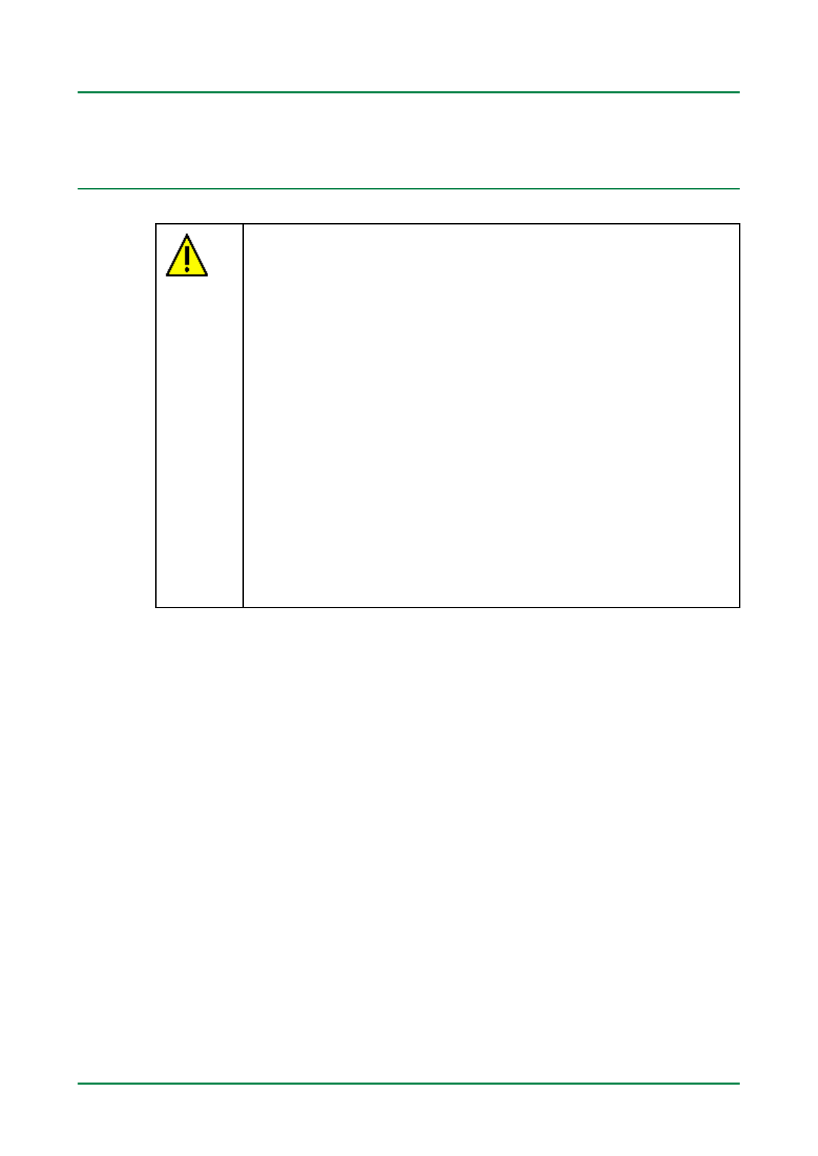
2.2 Intended use
The BMA/BMB Tool (Brake Maintenance A or B model) is a rake
maintenance tool for filling and leeding hydraulic systems containing
rake fluid in motor vehicles, e.g. rake or clutch circuits. The BMA/BMB
Tool may only e used with DOT 3, DOT 4 or DOT 5.1 (glycol- ased) rake
fluid. Hydraulic fluid ased on mineral oil or DOT 5 rake fluid (silicone-
ased) is not suita le for the BMA/BMB Tool and must therefore not e
used. As rake fluid is very hydroscopic (a sor s and retains moisture),
the BMA/BMB Tool must e stored and operated in dry conditions.
For maintenance of the hydraulic system, the BMA/BMB Tool is connected
to the associated rake fluid reservoir using a suita le adapter. A
pressurised electric pump delivers new rake fluid from the BMA Tool or
BMB Tool to the rake fluid reservoir. The supply pressure can e
continuously adjusted from 0 to 2.8 ar. The rake fluid current pulsates
during the leeding phase of the hydraulic system. These fluctuations
ena le a complete leeding process, as even the smallest amounts of air
or moisture at the pipe connections are carried away.
After switching off the electric pump, the pressure in the rake fluid
reservoir reduces and the correct rake fluid level is automatically set.
If the rake fluid container is emptied to the minimum filling level, the
pump switches off automatically. This ensures that air never gets into the
hydraulic system.
9

Tool description BMA/BMB-Tool
Tool description
2.3 Tool description
2.3.1 Front side of the BMA/BMB Tool
BMB Tool BMA Tool
DDeessii nnaattiioonn
1Handle
This can e used to carry or pull the BMA/BMB Tool (depending
on the model).
2Indicator light
The red indicator light shows the operating status of the BMA/
BMB Tool. If the indicator light is activated, this indicates a fault
in the hydraulic system.
3Pressure regulator
This is used to set the desired maintenance pressure of the rake
fluid.
4Quick guide
This provides a schematic description of the leeding procedure
of the rake system.
10

BMA/BMB-Tool Tool description
Tool description
DDeessii nnaattiioonn
5Storage compartment
Various leed components can e stored here.
6Holder for power cable
Here the power ca le can e stored away on the BMA/BMB Tool.
7Power cable for voltage supply
This supplies the BMA/BMB Tool with mains voltage.
8Pressure gauge
This displays the current rake fluid pressure in the BMA/BMB
Tool.
9Electrical fuse
This fuses the electric circuit (max. 230 V) of the tool.
10 Main switch
This is used to switch the BMA/BMB Tool on or off.
11 Start button for pump
This is used to switch the electric pump on or off. The electric
pump supplies the maintenance pressure for the rake fluid in
the BMA/BMB Tool and the hydraulic system of the vehicle.
11

Tool description BMA/BMB-Tool
Tool description
2.3.2 Rear of the BMA/BMB Tool
BMB Tool BMA Tool
DDeessii nnaattiioonn
12 Tank pipe
This sucks in the rake fluid from the rake fluid container and
returns it.
13 Fine filter
This filters out dirt particles in the rake fluid. This filter is
located in the intake line.
14 Storage compartment
This is where the rake fluid container is stored and, if
necessary, the leed components.
15 Closing cone
This seals the rake fluid container closed.
16 Holder for filler hose
The filler hose for rake fluid can e stored here.
12

BMA/BMB-Tool Tool description
Tool description
DDeessii nnaattiioonn
17 Filler hose with quick coupling
This conducts the rake fluid from the BMA/BMB Tool to the
vehicle hydraulic system.
18 Holder for bleed components
Bleed components can e stored here, e.g. receiver ottle or
adapter for the rake fluid reservoir.
13

Assem ly of the BMB Tool BMA/BMB-Tool
Assem ling the BMB Tool
3 Assembly of the BMB Tool
3.1 Assemblin the BMB Tool
Before initial start-up of the BMB Tool, the handle (1) (supplied separately)
may need to e fitted to the tool.
To fit the handle, proceed as follows:
1. Align the oreholes of the handle (1) with the oreholes (2) on top of
the tool and on the ottom plate (3).
2. Insert the plug-in nuts into the ottom oreholes of the handle.
3. Insert the 2 hexagon socket screws 6 x 12 mm through the oreholes
on the ottom plate into the plug-in nuts and fix loosely.
4. Insert the 2 hexagon socket screws 6 x 30 mm through the top
oreholes of the handle and fix loosely
5. Tighten all hexagon socket screws with a size 4 hexagon socket screw
key.
14

BMA/BMB-Tool Initial start-up
Preconditions
4 Initial start-up
4.1 Preconditions
• An adapter for the rake fluid reservoir is availa le.
• Brake fluid container with contents of at least 5 l is availa le.
4.2 Preparin the BMA/BMB Tool
To prepare the BMA/BMB Tool for initial start-up, proceed as follows:
1. Insert rake fluid container with at least 5 l content into the BMA/BMB
Tool.
2. Remove container seal.
3. Remove filling cap from the intake line of the tank pipe (12).
4. Slide the closing cone (15) of the tank pipe (12) all the way up.
5. Fit the tank pipe (12) to the container.
6. Slide the closing cone (15) onto the tank pipe (12) and press firmly
until the container opening is completely sealed.
7. Adjust the pressure regulator (3) to max. pressure y turning
clockwise until the end stop.
8. Use the main switch (10) to switch on the BMA/BMB Tool.
9. Press the start utton (11) to switch on the pump and hold down until
the pressure gauge (8) levels off at a constant value.
10. Use the main switch (10) to switch off the pump or BMA/BMB Tool.
11. Connect any adapter to the filler hose using the quick coupling (17).
12. Hold the adapter a ove a suita le container that is resistant to rake
fluid.
13. Use the main switch (10) to switch on the BMA/BMB Tool.
14. Use the start utton (11) to switch on the pump again.
Brake fluid is pumped into the container.
15. Continue with the pump procedure until rake fluid comes out of the
filler hose free from u les.
16. Use the main switch (10) to switch off the pump or BMA/BMB Tool.
17. Remove adapter for filler hose.
15

BMA/BMB-Tool Working with the BMA/BMB Tool
Adjusting the working pressure
5 Workin with the BMA/BMB Tool
5.1 Adjustin the workin pressure
The required working pressure can e continuously adjusted using the
pressure regulator (3) etween approx. 0 and approx. 2.8 ar depending
on the rake system or maintenance work. The current pressure can e
read from the pressure gauge (8). The default working pressure is approx.
2.1 ar.
CAUTION
Excessive pressure may cause the rake fluid reservoir to
reak or the connecting hoses to come loose.
Uncontrolled leak of rake fluid.
Always use the working pressure prescri ed in the
manufacturer or service documents.
To set the working pressure, proceed as follows:
1. Connect suita le adapter to the vehicle.
2. Remove the filler hose from the adapter.
Alternatively, the pressure can also e adjusted with the filler hose
connected.
3. Use the main switch (10) to switch on the BMA/BMB Tool.
4. Switch on the pump using the start utton (11).
Pressure gauge displays the currently set working pressure.
5. Adjust the working pressure using the pressure regulator (8) and read
off the current pressure from the pressure gauge.
Turning the pressure regulator to the left reduces the pressure.
Turning the pressure regulator to the right increases the pressure.
6. Use the main switch (10) to switch off the pump or BMA/BMB Tool.
7. Attach filler hose to adapter with quick coupling (17).
The working pressure is now set.
5.2 Brake systems with brake pressure re ulator
In rake systems with a load-dependent rake pressure regulator, when
carrying out maintenance work with an unloaded rear axle the working
17

Working with the BMA/BMB Tool BMA/BMB-Tool
Changing the rake fluid/ leeding the hydraulic system
pressure stipulated y the vehicle manufacturer must e set on the BMA/
BMB Tool (see section Adjusting the working pressure (Page 17)). Only
then can it e ensured that the rake pressure regulator does not reduce
the working pressure.
As an alternative to adjusting the working pressure, the rear axle of the
vehicle can e loaded or an axle load can e simulated y moving the
connecting springs etween the rear axle and rake pressure regulator.
5.3 Chan in the brake fluid/bleedin the hydraulic system
5.3.1 Preconditions
• Suita le adapter for the rake fluid reservoir is availa le.
• Sufficient rake fluid in the rake fluid container.
5.3.2 Maintenance via the brake fluid reservoir
This section descri es the maintenance of the hydraulic system when the
BMA/BMB Tool is connected to the rake fluid reservoir and the rake
fluid escapes via the leed screw.
To carry out maintenance, proceed as follows:
1. Mount a suita le adapter on the rake fluid reservoir.
2. Attach filler hose to adapter with quick coupling (17).
3. Use the main switch (10) to switch on the BMA/BMB Tool.
CAUTION
Excessive pressure may cause the rake fluid reservoir to
reak or the connecting hoses to come loose.
Uncontrolled leak of rake fluid.
Always use the working pressure prescri ed in the
manufacturer or service documents.
4. Switch on the pump using the start utton (11).
Pressure gauge displays the currently set working pressure.
18

BMA/BMB-Tool Working with the BMA/BMB Tool
Changing the rake fluid/ leeding the hydraulic system
5. Set the correct working pressure using the pressure regulator (8) and
read off the current pressure from the pressure gauge.
Turning the pressure regulator to the left reduces the pressure.
Turning the pressure regulator to the right increases the pressure.
Maintenance can now e carried out via the leed screw of the rake
calliper, wheel rake cylinder or clutch cylinder.
6. Bring the vehicle to working height.
7. Connect hose from receiver ottle for rake fluid to leed screw.
8. Use a suita le wrench to hold open the leed screw until new rake
fluid escapes without u les.
9. Close the leed screw.
10. Repeat steps 7-9 for additional leed screws.
11. Use the main switch (10) to switch off the pump or BMA/BMB Tool.
CAUTION
Never loosen the adapter from the rake fluid reservoir
while the system is pressurised.
Overflowing of the container or uncontrolled leak of rake
fluid.
Always switch off the BMA/BMB Tool first and wait for the
pressure to reduce.
12. Wait approx. 15 s until the pressure has reduced.
13. Remove the adapter from the rake fluid reservoir.
14. Dispose of any collected rake fluid in an environmentally friendly
manner.
5.3.3 Fillin up the brake fluid reservoir
To fill up the rake fluid reservoir, proceed as follows:
1. Connect any adapter to the filler hose using the quick coupling (17).
2. Hold the adapter a ove the open rake fluid reservoir.
3. Use the main switch (10) to switch on the BMA/BMB Tool.
19

Working with the BMA/BMB Tool BMA/BMB-Tool
Checking the wheel rake cylinders for free movement
4. Switch on the pump using the start utton (11).
NOTE
The rake fluid reservoir must e filled with rake fluid up
to the marking MAX.
Brake fluid flows pressure-free into the rake fluid reservoir.
5. Use the main switch (10) to switch off the pump or BMA/BMB Tool.
5.4 Checkin the wheel brake cylinders for free movement
To check the wheel rake cylinders for free movement, proceed as
follows:
1. Connect a suita le adapter for the rake fluid reservoir to the vehicle.
2. Using the pressure regulator (3), set the working pressure to
minimum (see section Adjusting the working pressure (Page 17)).
3. Attach filler hose to adapter with quick coupling (17).
4. Use the main switch (10) to switch on the BMA/BMB Tool.
5. Switch on the pump using the start utton (11).
6. Using the pressure regulator (3), gradually increase the working
pressure to the maximum maintenance pressure approved y the
manufacturer.
7. Turn the wheels to check that the raking effect is the same on all
axles.
If the raking effect varies on the wheels, this may e caused y the
following:
• Wheel rake cylinder or rake calliper stiff or leaking.
• Different settings of the rake shoes in the drum rake.
• Brake shoes or rake linings worn.
• Brake pressure regulator or rake pressure valves faulty.
20
This manual suits for next models
1
Table of contents
Other Hella Gutmann Test Equipment manuals

Hella Gutmann
Hella Gutmann CSC-Tool SE User manual

Hella Gutmann
Hella Gutmann SEG V User manual

Hella Gutmann
Hella Gutmann CSC-Tool User manual

Hella Gutmann
Hella Gutmann SEG IV User manual

Hella Gutmann
Hella Gutmann CSC-Kit Radar I User manual

Hella Gutmann
Hella Gutmann SEG Series Manual

Hella Gutmann
Hella Gutmann CSC-Tool User manual

Hella Gutmann
Hella Gutmann Radar Kit III User manual

Hella Gutmann
Hella Gutmann mega macs PC User manual

Hella Gutmann
Hella Gutmann CSC-Kit Radar II User manual