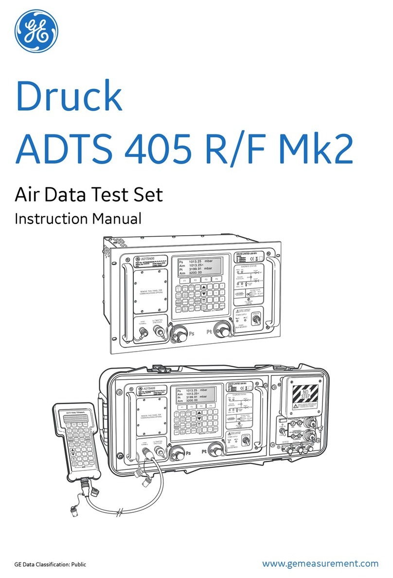
GE ADTS 405F Mk2 Setup guide

www.gemeasurement.com
GE Data Classification: Public
Druck
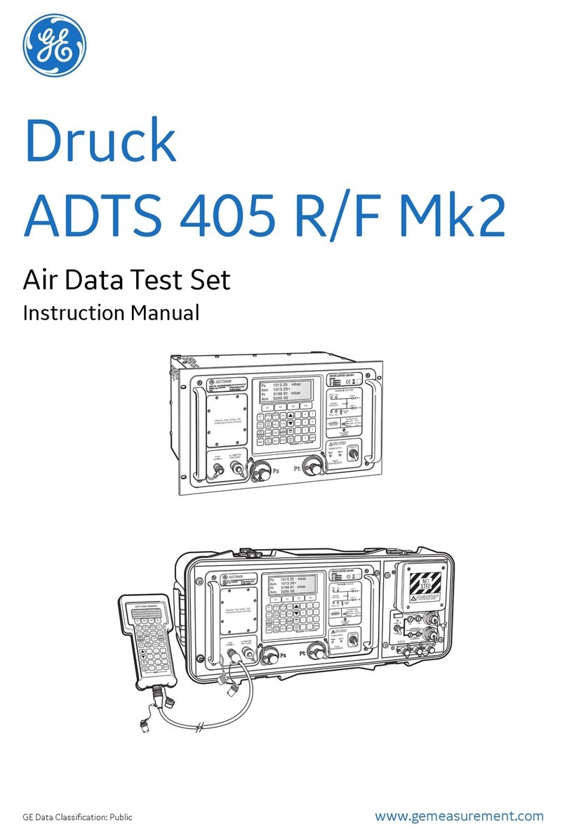
ADTS 405 R/F Mk2
Air Data Test Set
Safety and Installation Guide
[EN] English 1 - 9
[BG] Български 11 - 20
[CS] čeština 21 - 29
[DA] Dansk 31 - 39
[DE] Deutsch 41 - 50
[EL] Ελληνικά 51 - 60
[ES] Español 61 - 70
[ET] Eesti keel 71 - 79
[FI] Suomi 81 - 89
[FR] Français 91 - 100
[HI] 101 - 110
[HR] Hrvatski 111 - 120
[HU] magyar 121 - 130
[IS] Íslenska 131 - 139
[IT] Italiano 141 - 150
[JA] মୁ 151 - 160
[KO] ଞ˲߭ 161 - 169
[LT] Lietuvių171 - 179
[LV] Latviešu 181 - 189
[MT] Malti 191 - 199
[NB] Norsk 201 - 209
[NL] Nederlands 211 - 219
[PL] Polski 221 - 230
[PT] Português 231 - 240
[RO] Română241 - 250
[RU] Русский 251 - 260
[SK] Slovenčina 261 - 269
[SL] Slovenščina 271 - 280
[SV] Svenska 281 - 289
[TR] Türkçe 291 - 299
[UR] اُردُو 301 - 309
[ZH] Иކ 311 - 319
ADTS HAND TERMINAL
POWERSUPPLY
100/120/230V~50/60Hz500VA
115~400Hz500VA
FUSES
T5.0A250VHRC
POWERSUPPLY24-30V
FUSES
500VA
T20A T32A


124M8686 Revision A
12
3
4
5
6
100/120/230V~50/60Hz
115V~400Hz
400VA
FUSED2x
T5A250VHRC
AC
INPUT
~
24-30V
400VA
DC
INPUT
11
1514
13 12
10
9
8
7
#1
#2
#3
#4

124M8686 Revision A
POWERSUPPLY
100/120/230V~50/60Hz500VA
115~400Hz500VA
FUSES
T5.0A250VHRC
POWERSUPPLY24-30V
FUSES
500VA
T20A T32A
ADTS HAND TERMINAL
12
3
4
5
6
7
9
10
11
12
1314
15
16
17
8
5
67
8
9
1
2
3
4
#6
#5

[EN] English 124M8686 Revision A
Marks and Symbols on the equipment
This equipment meets the requirements of all relevant European safety
directives. The equipment carries the CE mark.
This symbol, on the equipment, indicates that the user should read the user
manual.
This symbol, on the equipment, indicates a warning and that the user should
refer to the user manual.
This symbol warns the user of the danger of electric shock.
Do not dispose of this product as household waste. Use an approved
organisation that collects and/or recycles waste electrical and electronic
equipment. For more information, contact one of these:
- Our customer service department: www.gemeasurement.com
- Your local government office.
For the list of GE approved service centres, go to: www.gemeasurement.com
© 2017 General Electric Company. All Rights Reserved. Specifications are subject to
change without notice. GE is a registered trademark of General Electric Company.
Other company or product names mentioned in this document may be trademarks
or registered trademarks of their respective companies, which are not
affiliated with
GE.
1

[EN] English 124M8686 Revision A
1. Introduction
This manual provides safety information applicable to installation and
operation requirements compatible with first line Air Data Test Set of the ADTS
405 pressure controller available in models:
R - Rack mounted (19” 6U).
F - Flightline cased (including pressure/vacuum pump rack).
The ADTS 405F and ADTS 405R are typically used in different working
environments requiring different connections and precautions.
For details of calibration requirements for the ADTS, refer to Calibration
Manual K0199.
For details of available manufacturer specified parts, refer to the current
revision of the product data sheet.
Service/maintenance and repair will be carried out at GE authorised service
centres.
1.1. Intended use
This guide provides preliminary safety details of aircraft aeronautical pressure
instrumentation, located indoor in a hanger, calibration laboratory or outdoor
runway.
The manufacturer has designed this equipment to be safe when operated
using the procedures detailed in this manual. If the equipment is used in a
manner not specified by this document and User Manual K0572 the protection
provided by the equipment may be impaired.
WARNING
THIS EQUIPMENT IS NOT RATED FOR USE IN POTENTIALLY
EXPLOSIVE ATMOSPHERES. USING THIS EQUIPMENT IN A
POTENTIALLY EXPLOSIVE ATMOSPHERE COULD LEAD TO SERIOUS
INJURY OR DEATH.
1.2. Safety
Examine all equipment to be used with specific observation of
electrical leads and connectors and pneumatic pipes and connectors.
CAUTION: DO NOT USE ANY EQUIPMENT THAT IS KNOWN OR SUSPECTED TO
BE DAMAGED OR FAULTY.
2. Power supply
Ensure electrical power is applied at the values stated. Confirm that
the power supply is off before connecting the power cable.
The electrical supply must be connected in accordance with local wiring and
supply regulations.
2

[EN] English 124M8686 Revision A
WARNING
THE ADTS MUST BE CONNECTED TO A SUPPLY PROTECTIVE
EARTH/GROUND AT ALL TIMES TO AVOID RISK OF ELECTRIC SHOCK OR
ELECTROCUTION.
The power supply cable and connector must be correctly rated for the power
supply. Only use power cables supplied by GE specifically for the ADTS405.
AC Single
phase
(standard)
100/120/230 Vac, 50/60Hz
500 VA Max –ADTS 405F
115 Vac, 400Hz
100/120/230 Vac, 50/60Hz
400 VA Max –ADTS 405R
115 Vac, 400Hz
DC
(option
405F)
16 to 30 Vdc
500 VA Max –ADTS 405F
2.1. AC Power supply connection
European Colour
US Colour
Function
Brown
Black
Live
Blue
White
Neutral
Green/Yellow
Green
Protective Earth (Ground)
2.2. AC Fuses
Two 20mm High Breaking Capacity AC fuses are connected in the live and
neutral supply circuit and protect the entire unit. The AC fuses are rated at
T5AH 250V. On the ADTS 405F fuses are located in the holders mounted on the
pump rack front panel (see Figure 5). On the ADTS 405R fuses are located in
the holder mounted on the power input connector on the rear of the rack (see
Figure 3).
2.3. DC Power supply connection (option)
European Colour
US Colour
Function
Grey
Gray
+28V
White
White
0V Return
Wire Braid
Wire Braid
Protective Ground
2.4. DC Fuses (option)
On the ADTS 405F, two 1.25” Time Lag fuses are located in the holders
mounted on the pump rack front panel and protect the entire unit.
On the ADTS 405R, DC overcurrent protection fusing is internal and not user
serviceable.
3

[EN] English 124M8686 Revision A
3. Installation
3.1. Ventilation and Cooling (Figure 1 & Figure 2)
The cooling air inlet for the unit must not be obstructed. The ventilation holes
for the outlet of cooling air allow a free flow of air through and around the unit,
especially at high ambient temperatures.
The ADTS 405R rack-mounted version fits in a standard 6U height 19-inch rack.
There must be enough space at the rear of the unit for all the cables and pipes.
The length of the cables and pipes must allow for the removal and fitment of
the unit in the equipment rack.
Note: When installing the ADTS 405R into a system, the installation
technician is also responsible for the safety of the system.
3.2. Pressure and Vacuum Services
The pressure source should be clean dry air or Nitrogen at a pressure of 3.5 bar
gauge minimum to 6 bar gauge maximum (51 to 90 psi gauge). The ADTS 405R
has an internal regulator to protect the controllers. Filtering should be to better
than 15 microns and available flow rate greater than 2.8 litres/min (0.1 cubic
ft/min) at the above pressure. The Vacuum source should be 20 mbar absolute
(0.3 psi absolute), or lower, with a flow rate capability greater than 11
litres/min (0.39 cubic ft/min).
3.3. Pneumatic Connections (Figure 3, Figure 4 & Figure 5)
In normal operation make sure that the correct blanking caps are fitted to the
external connectors.
Notes:Blanking caps must be fitted on unused front or rear outputs.
A leak of this blanking cap affects the performance of the ADTS 405F.
Static (Ps) -----------------------------------------------------
AN-6, 37° flare
AN-4, 37° flare
AN-4 37° flare
AN-6 37° flare
AN-4 37° flare
Pitot (Pt) ------------------------------------------------------
External Pressure supply -----------------------------------
External Vacuum supply ------------------------------------
Auxiliary vacuum output (optional) -----------------------
Notes:
Any optional configuration of bulkhead connector sizes available for the ADTS
405F can be fitted as specified.
On the ADTS 405R Expansion Port Plug (15) MUST be fitted if expansion port
(14) is not in use with external GE PV103R pump.
4

[EN] English 124M8686 Revision A
3.4. ADTS 405F/R Output Specification
Hoses (available as orderable accessories on the datasheet) are used for
connection to the “Pitot” (Pt) and “Static” (Ps) output ports of the ADTS. The
“Pitot” (Pt) and “Static” (Ps) outputs can then be connected to the
corresponding Pitot and Static connectors on the aircraft or aeronautical
instruments.
MAX Ps output pressure - 1355 mbar absolute.
MAX Pt output pressure - 3500 mbar absolute.
The following table details the possible connector specifications:
G1/8
Pipe Thread ISO 228 - G 1/8 B
AN4
7/16 - 20 UNJF - 3A Thread
AN6
9/16 - 18 UNJF - 3A Thread
Note: Mating female parts are available from GE
4. Power up and Self-Test
The wall socket connection must remain accessible.
The Power Switch is not a disconnecting device. To disconnect power
to the test set, either:
Remove the power cable connection from the Air Test rack, OR
Remove the power cable from the wall socket.
An external earth/ground connection stud (Item 6, Figure 5) is
available as a functional earth on the ADTS 405F front panel to
provide a connection point for equipotential cross bonding with other
equipment connected to the same earth/ground connection as the test set.
This is not a protective earth/ ground connection.
Fit “Pitot” (Pt) and “Static” (Ps) port blanks.
405F ONLY
Use the Power Switch on the front of the pump rack (11) to turn on the
internal source pressure and vacuum services for the ADTS.
405R ONLY
Connect an external source pressure hose to the rear connector (10) and an
external source vacuum hose to rear connector (11).
Connect the expansion port loop plug (15) to the expansion port (14) on the
rear of the rack.
Ensure that the test set is connected to an external power supply at the AC
(or DC) connectors and the supply is switched on. Use the Power Switch to
turn on the main test set.
5

[EN] English 124M8686 Revision A
The test set performs a self-test, resulting in a test set system colour status
indication of either “READY”, “NOT READY” or “FAULT”.
The states of the main pressure control and pneumatic isolation valves
associated with protecting connected aircraft systems are presented on the
mimic panel (see Figure 6) both during and after self-test.
When status indicators Static Ground Vent (4) and Zero Ps/Pt cross vent (7)
are illuminated (Red) the test set is in the ‘SAFE AT GROUND’ state and the
external aircraft system may be safely connected or disconnected.
Note: If the self-test fails, or for any other reason the test set is considered to
be unserviceable, contact GE and return the test set to the GE or GE approved
service centre.
Power and self-test:
-Pressure controller rack switched on (On)
-Not Ready, self-test in progress (Orange)
-Ready, self-test passed (Green)
-Fault (Red)
5. Dimensions
CAUTION: THE ADTS 405F SHOULD BE LIFTED BY A MINIMUM
OF TWO PEOPLE.
The ADTS 405F can be moved by use of the handles and wheels.
ADTS 405F
Weight
29kg (64lb)
Height
442mm
Depth
332mm (front to rear)
Width
755mm (left to right)
ADTS 405R
Weight
12kg (26.5lb)
Height
6U
Depth
255mm (front to rear, behind mounting panel)
Width
19” Rack Mount
ADTS Remote
Hand
Terminal
Weight
1kg (2.2lb)
Height
270mm
Depth
45mm
Width
125mm
6

[EN] English 124M8686 Revision A
6. Cleaning
CAUTION: DO NOT USE SOLVENTS TO CLEAN THIS EQUIPMENT.
Clean the external surfaces of the unit using a lint-free cloth and / or a soft
brush. Clean the electrical connector using a soft brush. Remove stubborn dirt
using a damp cloth and mild detergent. Allow to dry.
Note: All cleaning materials are commercially available items. Equivalent
alternatives may be used.
7. Product labelling
The product label for
the ADTS 405F can
found on the front
facing side of the
enclosure.
Product label 1. for
the ADTS 405R can be
found on the front
panel top left corner
recess.
Product label 2 for the
ADTS 405R can be
found on the front
panel top right corner
recess.
The product label for
the ADTS Remote
Terminal can be
found on the rear of
the rubber casing.
7

[EN] English 124M8686 Revision A
8. Operating Environment
WARNING
THIS EQUIPMENT IS NOT RATED FOR USE IN POTENTIALLY
EXPLOSIVE ATMOSPHERES.
Storage
temperatures
ADTS 405F: -51°C to 70°C (-60° to 158°F)
ADTS 405R: -51°C to 70°C (-60° to 158°F)
ADTS Remote Terminal: -51°C to 70°C (-60° to 158°F)
Operating
temperatures/
environment
ADTS 405F: -40°C to +55°C (-40° to 131°F)
ADTS 405R: -20°C to 50°C (-4° to 122°F)
ADTS Remote Terminal: -40°C to 50°C (-40° to 122°F)
Operating humidity: 5% to 95% RH (condensing)
Indoor & Outdoor use
AC Power supply
*Universal input Mains Power Supply.
Class 1 equipment requiring a protective earth connection.
†The supplied mains/PSU cable protective earth/ground
conductor must be connected to the power supply protective
earth/ground system.
TXAH 250V HRC Time-delay (T) 250V a.c. rated fuses
(5A fuse)
Overvoltage category II, Pollution degree 3
DC Power supply
(optional 405F)
24 to 30 V
†The supplied mains/PSU cable protective earth/ground
conductor must be connected to the power supply protective
earth/ground system.
T20A / T32A 250V DC fuses
Pollution degree 3
Electrical safety
EN 61010-1, IEC 61010-1
Operating
altitude
Maximum 15,000ft (4572 metres)
Ingress
protection
ADTS 405F: MIL-PRF-28800 Class 2
ADTS 405R: IP23
ADTS Remote Terminal: IP65 (EN60529)
* Refer to local guidelines and regulations for power supply and electrical
connection recommendations.
8

[EN] English 124M8686 Revision A
ADTS Function
405R
Figure
3 & 4
405F
Figure
5
Pneumatic isolation and control valve status display
1
1
System status indicator
2
2
DC Power supply fuses (option)
-
3
AC fuses holder
8
4
DC Power supply input connector (option)
-
5
External equipotential cross bonding point (option)
-
6
AC Power supply input connector
7
7
External source vacuum input connector
11
8
Auxiliary vacuum output connector (option)
-
9
Pressure regulator
9
-
External source pressure input connector
10
10
Pump rack power switch
-
11
Air data test set rack power switch
3
12
Pitot channel controlled pressure output connector
4
13
Static channel controlled pressure output connector
5
14
Remote hand terminal connector
6
15
Hand terminal connector cable (2m or 18m)
As 405F
16
Remote hand terminal
As 405F
17
Rear Static channel controlled pressure output
connector
12
-
Rear Pitot channel controlled pressure output
connector
13
-
Expansion port
(optional use with external GE PV103R
pressure/vacuum pump)
14
-
Expansion port loop closure plug
(mandatory if port not in use)
15
-
9

[EN] English 124M8686 Revision A
10

[BG] Български 124M8686, редакция A
Знаци исимволи на устройството
Това устройство отговаря на изискванията на всички релевантни
Европейски директиви за безопасност. Устройството носи маркировката
CE.
Наличието на този символ на устройството показва, че потребителят
трябва да прочете ръководството за потребителя.
Наличието на този символ на устройството показва предупреждение иче
потребителят трябва да направи справка връководството за
потребителя.
Този символ предупреждава потребителя за опасност от токов удар.
Не изхвърляйте този продукт като битов отпадък. Използвайте одобрена
агенция за сметосъбиране и/или рециклиране на електрически
иелектронни устройства. За повече информация се свържете седно от
следните:
–нашия отдел за обслужване на клиенти: www.gemeasurement.com
–вашата местна държавна агенция.
За списък содобрените сервизни центрове на GE отидете на:
www.gemeasurement.com
© 2017 General Electric Company. Всички права запазени. Спецификациите
подлежат на променя без предизвестие. GE ерегистрирана търговска марка на
General Electric Company. Други фирмени или продуктови имена, споменати
втози документ, могат да са търговски марки или регистрирани търговски
марки на съответните притежатели, които да не са свързани по някакъв начин
сGE.
11

[BG] Български 124M8686, редакция A
1. Въведение
Това ръководство предоставя информация за безопасност, приложима за
процедурите на монтиране иработа от първи ред на инструмента за
тестване на въздухоплавателни данни на контролера на налягането ADTS
405, наличен вследните модели:
R –рафтово монтиран (19-инчов 6U).
F –вграден влетателния апарат (включително рафта на помпата за
налягане/вакуум).
ADTS 405F иADTS 405R стандартно се използват вразлични работни среди
иизискват различни връзки ипредпазни мерки.
За подробности за изискванията за калибриране на ADTS направете
справка връководството за калибриране K0199.
За подробности за налични определени от производителя части
направете справка вактуалното издание на листа сданни за продукта.
Обслужването/поддръжката иремонтът трябва да се извършват от
оторизирани сервизни центрове на GE.
1.1. Предвидена употреба
Това ръководство предоставя предварителни данни за безопасността на
авиационни инструменти за измерване на налягане, разположени на
закрито вхангар, лаборатория за калибриране или на открито на писта.
Производителят епредвидил използването на това устройство да бъде
безопасно при спазване на процедурите, описани втова ръководство. Ако
устройството се използва по начин, който не епосочен втози документ
иръководството за потребителя K0572, защитата, предоставена от
устройството, може да бъде влошена.
ПРЕДУПРЕЖДЕНИЕ
ТОВА УСТРОЙСТВО НЕ ЕПРЕДНАЗНАЧЕНО ЗА РАБОТА
ВПОТЕНЦИАЛНО ЕКСПЛОЗИВНИ СРЕДИ. ИЗПОЛЗВАНЕТО НА ТОВА
УСТРОЙСТВО ВПОТЕНЦИАЛНО ЕКСПЛОЗИВНИ СРЕДИ МОЖЕ ДА
ДОВЕДЕ ДО СЕРИОЗНО НАРАНЯВАНЕ ИЛИ СМЪРТ.
1.2. Информация, свързана сбезопасността
Огледайте всички устройства, които ще се използват, като
обърнете специално внимание на електрическите кабели
ивръзки ипневматичните тръби иконектори.
ВНИМАНИЕ: НЕ ИЗПОЛЗВАЙТЕ НИКАКВИ УСТРОЙСТВА, ЗА КОИТО
ЕИЗВЕСТНО ИЛИ СЕ ПОДОЗИРА, ЧЕ СА ПОВРЕДЕНИ ИЛИ ДЕФЕКТНИ.
12

[BG] Български 124M8686, редакция A
2. Захранване
Уверете се, че подаваното електрозахранване еспосочените
стойности. Уверете се, че захранването еизключено, преди да
свържете захранващия кабел.
Електрозахранването трябва да есвързано всъответствие сместните
наредби за окабеляване иподаване на електричество.
ПРЕДУПРЕЖДЕНИЕ
ADTS ТРЯБВА ДА ЕСВЪРЗАНО КЪМ ПРЕДПАЗВАЩО
ЗАХРАНВАНЕТО ЗАЗЕМЯВАНЕ ПО ВСЯКО ВРЕМЕ, ЗА ДА СЕ ИЗБЕГНЕ
ОПАСНОСТТА ОТ ТОКОВ УДАР.
Захранващият кабел иконекторът трябва да са справилните номинални
стойности за даденото електрозахранване. Използвайте само
захранващи кабели, предоставени от GE специфично за ADTS405.
Променливотоково,
еднофазово
(стандартно)
100/120/230 Vac, 50/60 Hz
500 VA макс. – ADTS
405F
115 Vac, 400 Hz
100/120/230 Vac, 50/60 Hz
400 VA макс. – ADTS
405R
115 Vac, 400 Hz
Постояннотоково
(вариант 405F)
16 до 30 Vdc
500 VA макс. – ADTS
405F
2.1. Свързване на променливотоково захранване
Цвят за Европа
Цвят за САЩ
Функция
Кафяво
Черно
Фаза
Синьо
Бяло
Нула
Зелено/жълто
Зелено
Защитно заземяване
(земя)
2.2. Предпазители за променливотоково захранване
Два 20-мм предпазителя за променливотоково захранване свисок
капацитет на прекъсване са свързани към фазата инулата изащитават
целия уред. Предпазителите за променливотоково захранване са
сноминална стойност T5AH 250 V. На ADTS 405F предпазителите се
намират вдържачите, монтирани на рафта на помпата (вж. Фигура 5). На
ADTS 405R предпазителите се намират вдържача, монтиран на конектора
за електрозахранване на гърба на рафта (вж. Фигура 3).
13

[BG] Български 124M8686, редакция A
2.3. Свързване на постояннотоково захранване (вариант)
Цвят за Европа
Цвят за САЩ
Функция
Сиво
Сиво
+28 V
Бяло
Бяло
0 V маса
Бял гайтан
Бял гайтан
Защитно заземяване
2.4. Предпазители за постояннотоково захранване (вариант)
ADTS 405F включва два 1,25" предпазителя срещу свръхток, които се
намират вдържачите, монтирани на предния панел на рафта на помпата,
ипредпазват целия уред.
На ADTS 405R предпазителите срещу свръхток за постояннотоково
захранване са вградени ине са достъпни за потребителя.
3. Монтиране
3.1. Проветряване иохлаждане (Фигура 1 иФигура 2)
Отворът за входящ въздух на уреда не трябва да бъде блокиран.
Вентилационните отвори за влизане на охлаждащ въздух позволяват
свободно движение на въздух през иоколо уреда, особено при висока
околна температура.
Вариантът срафтово монтиране ADTS 405R се побира встандартен 19-
инчов рафт свисочина 6U. Трябва да има достатъчно пространство на
гърба на уреда за всички кабели итръби. Дължината на кабелите
итръбите трябва да етакава, че да позволява изваждането ипоставянето
на уреда врафта за устройства.
Забележка: При монтиране на ADTS 405R всистема монтиращият
техник еотговорен иза безопасността на системата.
3.2. Източници на налягане ивакуум
Източникът на налягане трябва да ечист сух въздух или азот при
манометрично налягане от 3,5 бара минимум до 6 бара максимум (51 до
90 psi манометрично). ADTS 405R има вграден регулатор за защита на
контролерите. Филтрирането трябва да бъде по-добро от 15 микрона
иналичната скорост на потока по-висока от 2,8 литра/мин (0,1 куб.
фута/мин) при горепосоченото налягане. Източникът на вакуум трябва да
бъде сабсолютно налягане 20 mbar (абсолютно 0,3 psi) или по-ниско,
скапацитет за скорост на потока над 11 литра/мин (0,39 куб. фута/мин).
14

[BG] Български 124M8686, редакция A
3.3. Пневматични връзки (Фигура 3, 4 и5)
При стандартна работа се уверете, че на външните конектори са
поставени правилните затварящи капачки.
Забележки:Затварящи капачки трябва да се поставят ина
неизползвани предни или задни изходни отвори.
Утечки от затварящите капачки влияят на производителността на
ADTS 405F.
Статичен (Ps) ---------------------------------------
AN-6, 37° развалцовка
AN-4, 37° развалцовка
AN-6, 37° развалцовка
AN-4, 37° развалцовка
Пито (Pt) --------------------------------------------
Източник на външно налягане ------------------
Източник на външен вакуум --------------------
Изход за допълнителен вакуум (вариант) -----
Забележки:
Всякакви допълнителни конфигурации на размери преградни
конектори, налични за ADTS 405F, могат да се поставят според
указанията.
На ADTS 405R тапата на порта за разширяване (15) ТРЯБВА да
епоставена, ако портът за разширяване (14) не се използва за
помпата GE PV103R.
3.4. Спецификации на изходите на ADTS 405F/R
Маркучите (налични като аксесоари, които могат да се поръчат от
листовете сданни) се използват за свързване към изходните портове
"Пито" (Pt) и"Статичен" (Ps) на ADTS. Изходите "Пито" (Pt) и"Статичен" (Ps) на
свой ред могат да се свържат към съответните конектори "Пито"
и"Статичен" на въздухоплавателния съд или авиационните инструменти.
Макс. Ps изходно налягане – 1355 mbar, абсолютно.
Макс.Pt изходно налягане – 3500 mbar, абсолютно.
Следната таблица представя подробно възможните спецификации за
конекторите:
G1/8
Тръбна резба ISO 228 –G 1/8 B
AN4
7/16 –20 UNJF –3A резба
AN6
9/16 –18 UNJF –3A резба
Забележка: Съответстващите женски части са налични от GE
15

[BG] Български 124M8686, редакция A
4. Включване исамотестване
Свързването към стенния контакт трябва да остане достъпно.
Превключвателят на захранването не еустройство за
прекъсване. За да прекъснете захранването към инструмента за
тестване, направете едно от следните:
Извадете захранващия кабел от рафта на инструмента за тестване, ИЛИ
Извадете захранващия кабел от стенния контакт.
Външен заземяващ щифт (елемент 6, Фигура 5) еналичен като
функционално заземяване на предния панел на ADTS 405F за
осигуряване на точка за свързване за еквипотенциално
кръстосано свързване сдруги устройства, свързани към същата
заземяваща връзка. Това не езащитна заземяваща връзка.
Поставете тапите на портовете "Пито" (Pt) и"Статичен" (Ps).
САМО 405F
Използвайте превключвателя на захранването отпред на рафта за
помпата (11), за да включите вътрешните източници на налягане ивакуум
за ADTS.
САМО 405R
Свържете маркуч на външен източник на налягане към задния конектор
(10) имаркуч на външен източник на вакуум към задния конектор (11).
Поставете затварящата тапа на порта за разширяване (15) впорта за
разширяване (14) на гърба на рафта.
Уверете се, че инструментът за тестване есвързан към външен източник
на захранване при конекторите за променлив (или постоянен) ток иче
захранването евключено. Използвайте превключвателя на захранването,
за да включите основния инструмент за тестване.
Инструментът за тестване извършва самотестване, което дава като
резултат цветна индикация за състоянието на системата – "ГОТОВА",
"НЕГОТОВА", "НЕИЗПРАВНА".
Състоянията на управлението на основното налягане иклапаните за
пневматична изолация, свързани със защитата на свързаните
авиационни системи, се показват на мимичния панел (вж. Фигура 6) както
по време на, така ислед самотестването.
Когато индикаторите за състояние на статично вентилиране на земята (4)
инулево Ps/Pt кръстосано вентилиране (7) светнат (червено), инструментът
за тестване ев състояние "БЕЗОПАСЕН НА ЗЕМЯТА" ивъншната
авиационна система може безопасно да се свърже или връзката към нея
да се прекъсне.
16
This manual suits for next models
1
Table of contents
Languages:
Other GE Test Equipment manuals