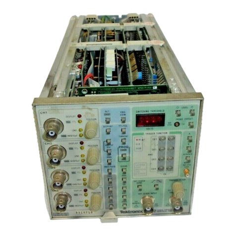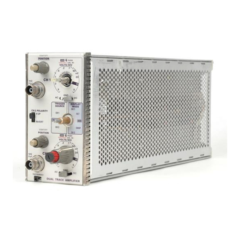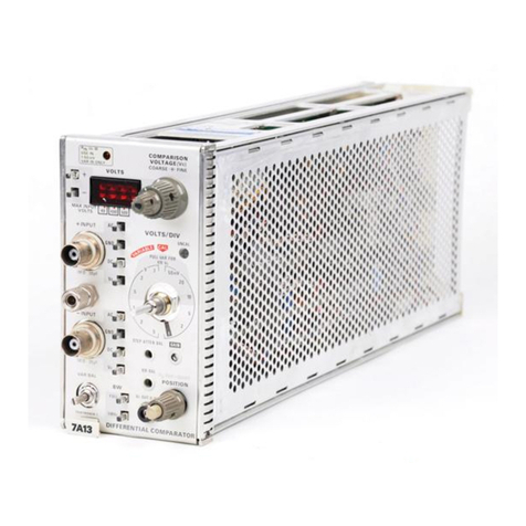
Type 7A13
SECTION
I
Change information,
if
any, affecting this section
will
be found at the
rear ofthe manual.
INTRODUCTION
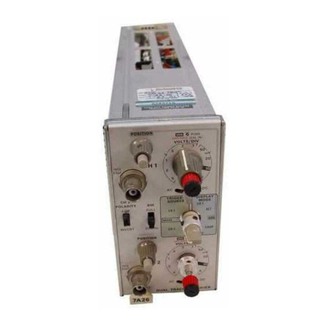
The Type 7A13 Vertical Plug-In
is
a DC coupled differential
comparator with excellent common-mode rejection and medi-
um gain characteristics for medium level applications. The
Type 71413 is designed for use inTektronix 7000 series oscillo-
scopes. It may be used as a differential input preamplifier
or conventional preamplifier in addition to its use as a com-
parator.
In the differential input mode, the dynamic range allows
the application of common-mode signals up to +10 or -10
volts to be applied to the unit without attenuation. Common-
mode reiection ratio of at least 20,000:1 at DC to 100kHz
permits measurements of differential signals less than 1 mV
in amplitudeon 10volt common-mode signals.
When used as a differential comparator, the Type 7A13
has an effective offset range of 10,000 divisions.
ELECTRICAL CHARACTERISTICS
The electrical characteristics described in Table 1-1 are
valid over the stated environmental range for instruments
calibrated at an ambient temperature of +20° C to +30°
C
and after a 20-minute warmup period unless otherwise noted.
TABLE
1-1
ELECTRICAL CHARACTERISTICS
Characteristic
Deflection Factor
(VOLTS/DIV)
Calibrated Range
Gain Ratio Accuracy
Uncalibrated (Vari-
able)
Common Mode Signal
Range
1mV/Div to
50 mV/Div;
XI0
Vc In
10mV/Div to
50 mV/Div;
XI0
Vc Out
0.1 V/Div to
0.5 V/Div;
XI0
Vc In
0.1 V/Div to
0.5 V/Div;
XI0
Vc Out
Characteristic
1V/Div to 5 V/Div;
XI0Vc In
DifferentialSignal Range
1mV/Div to
50 mV/Div;
XI0
Vc In
10mV/Div to
50 mV/Div;
XI0 Vc Out
0.1 V/Div to
0.5 V/Div;
XI0
Vc In
0.1 V/Div to
0.5 V/Div;
XI0
Vc Out
1V/Div to 5 V/Div;
XI0
Vc In
Frequency Response
(8 Div Reference)
FULL Bandwidth
Upper Limit
AC (Capacitive)
Coupled Input
Lower Bandwidth
,
Frequency
5MHz Bandwidth
Overdrive Recovery
(1
X
Attenuator at
1 mV/Div)
Common Mode Rejec-
tion Ratio
1mV/Div to
50 mV/Div
XlOVc In
'
DC to 100kHz
100kHz to 1MHz
1MHz to 10MHz
20MHz
10mV/Div to
50
mV/Div;
X
10Vc
Out;
0.1 V/Div to 5 V/Div;
XlOVc In or Out
DC to 10kHz
AC Coupled at 60 Hz
Performance Requirement
1mV/Div to 5V/Div, 12 steps in
a 1,2,5 sequence
Within 1.5% of GAIN adjusted
at 1 mV/Div
Continuously variable: extends
deflection factor to at least 12.5
V/Div
At least +10V and -lOV
At least +100V and -100V
At least +500 V and -500 V
Performance Requirement
At least +500 V and -500 V
At least 0.8 V
At least 8V
At least 80V
See Table 1-2, System Characteris-
tics
10Hz or less
DC to 5MHz within 500 kHz
1
pS to recover within 1.5 mV,
0.1 ms to recover within 0.5 mV,
following removal of a +10 V or
-10 V overdrive signal.
See Fig. 1-2.
At least 20,000:1, 20 V P-P or less
test signal
At least 10,000:1, 10V P-P or less
test signal
CMRR
=
10,000/frequency (MHz)
At least 250:1, 1V P-P or less test
signal
At least 2,000:l
At least 500:l
Scans by ArtekMedia © 2007
SECTION'
SPECIfICATION
Type 7A13
Change
information,
if
any,
affecting
this section will
be
found
at
the
rear
of
the
manual.
INTRODUCTION
The Type 7A13 Vertical Plug-In
is
a
DC
coupled differential
comparator
with excellent common-mode rejection
and
medi-
um
gain characteristics for medium level applications. The
Type 7A13
is
designed for use
in
Tektronix 7000 series oscillo-
scopes.
It
may
be
used
as
a differential input preamplifier
or
conventional preamplifier
in
addition to
its
use
as
a com-
parator.
In
the differential input mode, the dynamic
range
allows
the application of common-mode signals up to + 1°
or
-1
°
volts to
be
applied
to the unit without attenuation. Common-
mode rejection ratio of
at
least 20,000:1
at
DC
to 100
kHz
permits measurements of differential signals less than 1
mV
in
amplitude on 10 volt common-mode signals.
When
used
as
a differential
comparator,
the Type 7A13
has
an
effective offset
range
of 10,000 divisions.
ELECTRICAL
CHARACTERISTICS
The electrical characteristics described
in
Table
1-1
are
valid
over
the stated environmental
range
for instruments
calibrated
at
an
ambient
temperature of
+20
0 C to
+30
0 C
and
after
a 20-minute warmup period unless otherwise noted.
TABLE
1-1
ELECTRICAL
CHARACTERISTICS
Ch
aracteristic
Performance
Requirement
Deflection Factor
(VOL
TS/DIV)
Calibrated Range 1
mV
/Div to 5 V/Div, 12 steps
in
a 1, 2, 5 sequence
Gain
Ratio Accuracy Within 1.5%
of
GAIN adjusted
at
1 mVjDiv
Uncalibrated (Vari- Continuously variable: extends
able) deflection factor to
at
least 12.5
V/Div
Common
Mode
Signal
Range
1
mV
/Div to At least
+10V
and
-10V
50 mY/Diy;
X10
Vc
In
10mV/Divto
At least
+looV
and
-100V
50 mY/Diy;
X10
Vc
Out
0.1
V/Div to
0.5 V/Div;
X10
Vc
In
0.1
V/Div to At least
+500
V
and
-500
V
0.5 V/Div;
X10
Vc
Out
®
Characteristic
Performance
Requirement
1 V/Div to 5 V/Div; At least
+500
V
and
-500
V
X10
Vc
In
Differential Signal Range
1 mY/Diy to
At
least 0.8 V
50 mY/Diy;
X10
Vc
In
10mV/Divto
At least 8 V
50 mY/Diy;
X10
Vc
Out
0.1
V/Div to
0.5 V/Div;
X10
Vc
In
0.1
V/Div to At least 80 V
0.5 V/Div;
X10
Vc
Out
1 V/Div to 5 V/Div;
X10
Vc
In
Frequency Response
(8
Div
Reference)
FUll
Bandwidth See Table 1-2, System Characteris-
Upper limit tics
AC
(Capacitive) 10
Hz
or
less
Coupled Input
lower
Bandwidth ,
Frequency
5 MHz Bandwidth
DC
to 5 MHz within 500
kHz
Overdrive Recovery 1
fLS
to recover within 1.5mV,
(1
X Attenuator
at
0.1
ms
to recover within 0.5
mY,
1 mY/Diy) following removal of a
+10
V
or
-10
V overdrive signal.
Common Mode Rejec- See
Fig.
1-2.
tion Ratio
1 mY/Diy to
50
mV
/Div
X10Vc
In
DC
to 100
kHz
At least 20,000:1, 20 V
P-P
or
less
test signal
100
kHz
to 1 MHz At least 10,000:1, 10 V
P-P
or
less
test signal
1 MHz to
10MHz
CMRR
= 10,000/frequency
(MHz)
20MHz
At least 250:1, 1 V
P-P
or
less test
signal
10mV/Divto
50mV/Div;
X10Vc
Out;
0.1
V/Div to
5V/Div;
X10Vc
In
or
Out
DC
to 10
kHz
At least 2,000:1
AC
Coupled
at
60
Hz
At least 500:1
1-1
........
