Tektronix 7L5 User manual
Other Tektronix Measuring Instrument manuals
Tektronix
Tektronix CSA8000B Series User manual
Tektronix
Tektronix S-4 User manual

Tektronix
Tektronix TLA 7M3 Manual
Tektronix
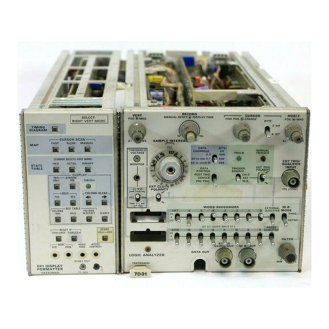
Tektronix 7D01 User manual
Tektronix
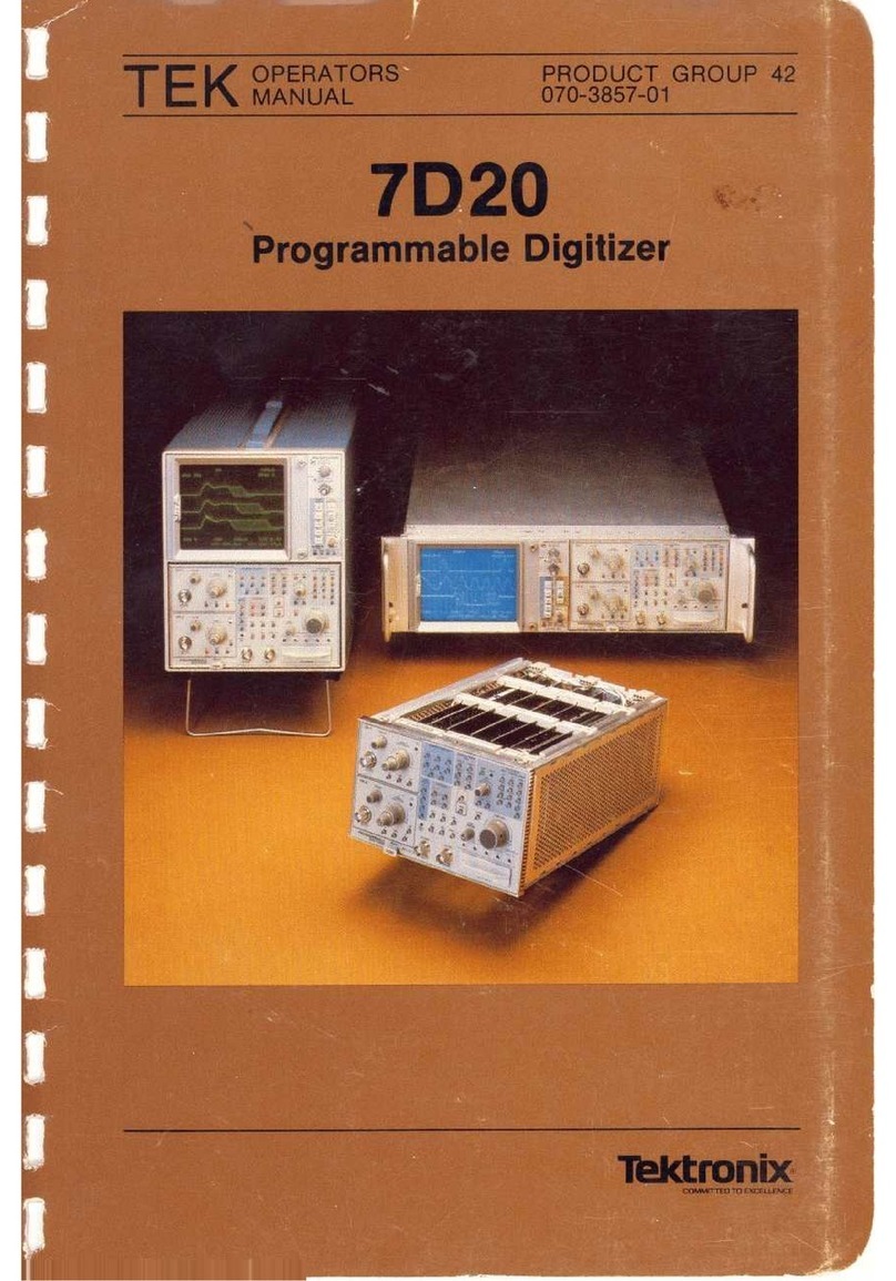
Tektronix 7D20 User manual
Tektronix
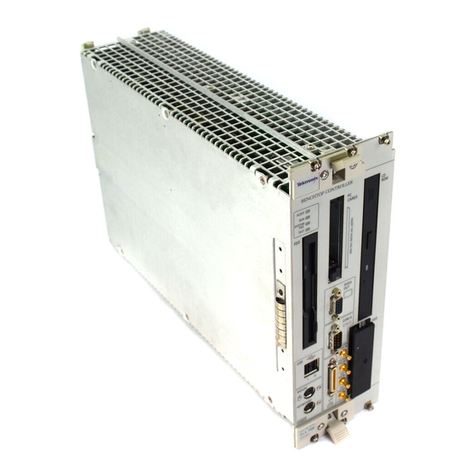
Tektronix P6434 User manual
Tektronix
Tektronix TLA 700 Series Product manual
Tektronix
Tektronix RSA3303A User manual
Tektronix
Tektronix 6 series User manual

Tektronix
Tektronix WVR5250 Manual

Tektronix
Tektronix 7D01 User manual
Tektronix
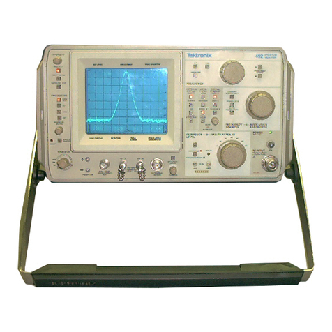
Tektronix 492, 492P User manual
Tektronix
Tektronix FCA3003 User manual
Tektronix
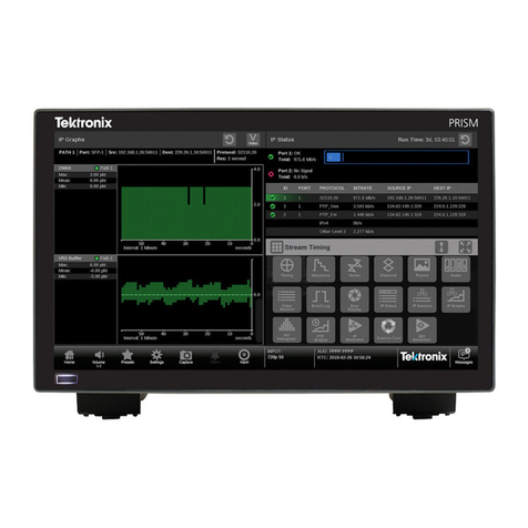
Tektronix PRISM User manual
Tektronix
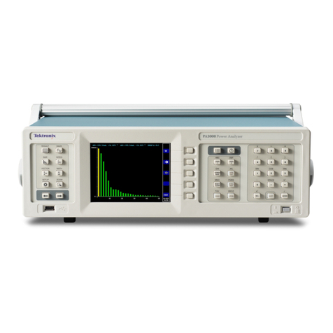
Tektronix PA3000 User manual
Tektronix
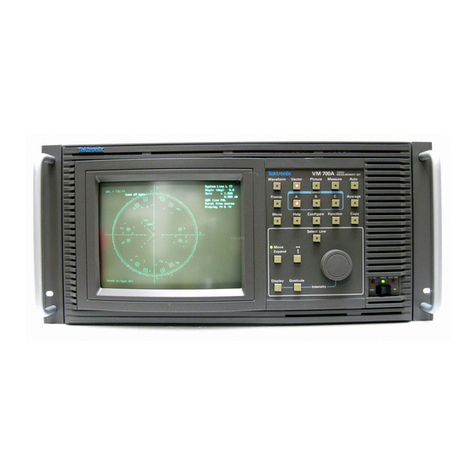
Tektronix VM700A VMTB User manual
Tektronix
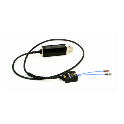
Tektronix TriMode P7700 Series Use and care manual
Tektronix
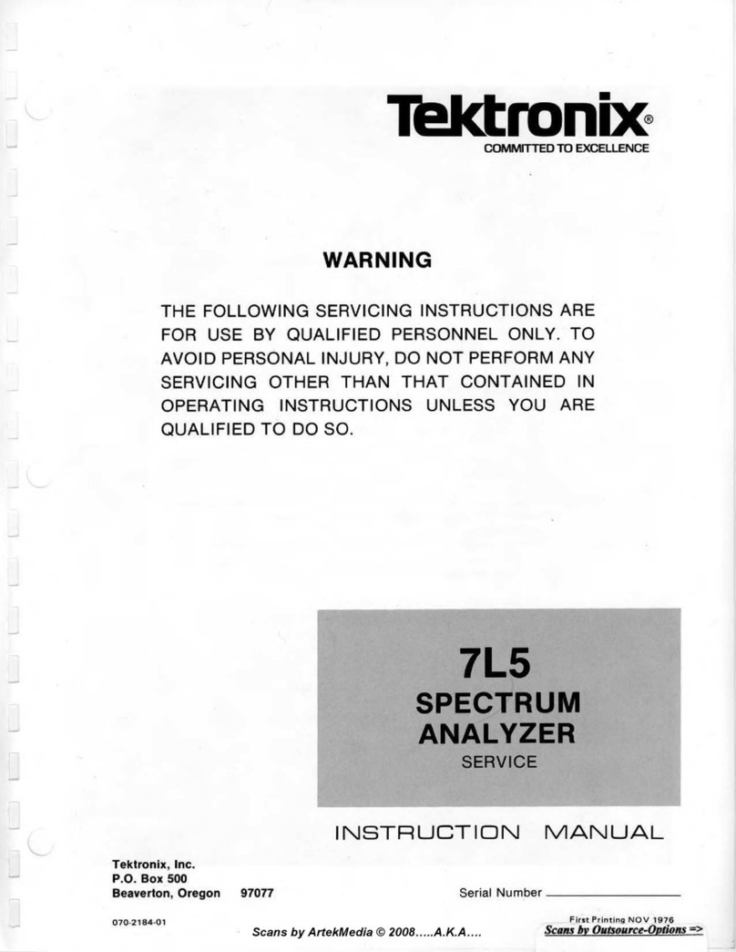
Tektronix 7L5 User manual
Tektronix
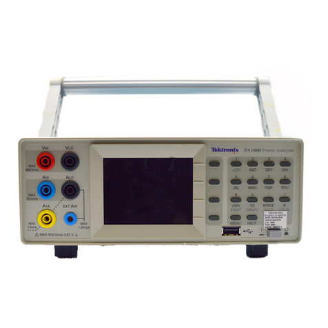
Tektronix PA1000 User manual
Tektronix
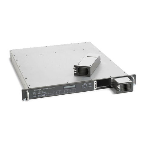
Tektronix ECO8000 Series User manual
Popular Measuring Instrument manuals by other brands

Powerfix Profi
Powerfix Profi 278296 Operation and safety notes

Test Equipment Depot
Test Equipment Depot GVT-427B user manual

Fieldpiece
Fieldpiece ACH Operator's manual

FLYSURFER
FLYSURFER VIRON3 user manual

GMW
GMW TG uni 1 operating manual

Downeaster
Downeaster Wind & Weather Medallion Series instruction manual

Hanna Instruments
Hanna Instruments HI96725C instruction manual

Nokeval
Nokeval KMR260 quick guide

HOKUYO AUTOMATIC
HOKUYO AUTOMATIC UBG-05LN instruction manual

Fluke
Fluke 96000 Series Operator's manual

Test Products International
Test Products International SP565 user manual

General Sleep
General Sleep Zmachine Insight+ DT-200 Service manual
