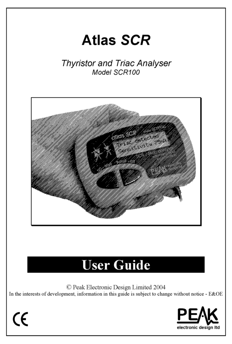
TEL T-48 Operating instructions

T-48/T-48A
MOD 3
50-400 HZ, SINGLE PHASE
120/220 VAC, 25 WATTS
120 VAC- 0.25 FTT, 220 VAC-0.125 FTT
T-48
MODE S/ATCRBS
TRANSPONDER RAMP
TEST SET
TEL-INSTRUMENT ELEC. CORP
TYPE WATTS
PART NO.
SERIAL NO.
INPUT 115/230 VAC 50-400HZ
CAGE CODE 92606 USA
MOD 1 2 3 4 5 6
TEST
INTERROGATE
ACCESSORIES
REPEAT
OFF
STORE
ANTENNA
LIGHTS
OFF
Transponder Test Set
Operating and Maintenance Manual
P/N-90000026
REVISION
Tel-Instrument Electronics Corp
728 Garden Street
Carlstadt, NJ 07072
(201) 933-1600
www.telinst.com
Leading the AVIONICS TEST industry into the 21st Century!
A B C D E F G H I J K L M
N O P Q R S T U V W X Y Z

FOREWORD
This manual provides and explains information pertinent to the operation, use and maintenance
of the Tel Instrument T-48/T-48A MOD 3 Test Set. Because aircraft systems vary dependent on
the type of aircraft, this manual is intended as a guideline. If further clarification or additional
information is necessary, please contact:
Tel Instrument Corp
Customer Support Division
728 Garden Street
Carlstadt, NJ 07072
(201) 933-1600
Tel Instrument Corp welcomes your input and/or comments concerning this publication. Every
effort has been made to ensure accuracy, but errors may occur. If you find an error or would like
to report a specific problem, please write the information down. Be as through as possible by
including the page/figure/table number and send the information to:
Tel Instrument Electronics Corp
Attention Technical Publications
We will make every effort to resolve the issue in a timely and professional fashion.
This manual will be revised occasionally when changes to the Test Set or its operation are
incorporated. If you feel you do not have the most current version of the manual, contact us with
the Test Set Model number, software version and current Rev Status of your manual. Every effort
will be made ensure you have the most up to date information that corresponds with your
equipment.
Copyright:
All rights reserved. Printed in the United States of
America. Except as permitted under the United States
Copyright Act, no part of this manual may be
reproduced or distributed in any form or by any means,
or stored in a database or retrieval system, without
written permission of Tel Instrument Corp. (2002)

Revision A T-48 90 008 026
i
T-48 MOD 3TABLE OF CHANGES
Date REV ECO Page Description
7-26-2002 A Initial Release

Revision A T-48 90 008 026
ii
Table of Contents
Chapter Page
Table of Changes……………………………………………………………………………… i
List of Illustrations…………………………………………………….……………………….vi
List of Tables……………………………………………………….…………………………. vii
I Introduction
Section A- General Information
1.1 Scope of Manual……………………………………………………………………...1-1
1.2 Purpose and Function of the Equipment……..……………………………………… 1-1
1.3 Regulatory Responsibilities…………………………………………..........................1-2
1.4 Warranty……………………………………………………………………………...1-2
1.5 Safety Considerations………………………………………………………………...1-3
Section B- Equipment Description
1.6 Specifications………………………………………………………………………... 1-4
1.7 Abbreviations, Acronyms, and Glossary of Terms………………….......................... 1-5
II Preparation for Use and Operation
Section A- General Information
2.1 General………………………………………………………………......................... 2-1
2.2 Unpacking…………………………………………………………………………… 2-1
2.3 Installation……………………………………………………………………………2-1
2.4 Accessories…………………………………………………………………………...2-1
Section B- Operating Controls, Indicators, and Connectors
2.5 General………………………………………………………………......................... 2-3
2.6 Controls, Indicators, and Connectors………………………………………………... 2-3

Revision A T-48 90 008 026
iii
Table of Contents (continued)
Chapter Page
Section C- Operating Instructions
2.7 General………………………………………………………………......................... 2-5
2.8 Battery Operation……………………………………………………………………. 2-5
2.8.1 220 VAC Operation…………………………………………………………...2-5
2.9 Supplied Antennas…………………………………………………............................2-6
2.9.1 Omni-Directional Antenna……………………………………........................ 2-6
2.9.2 Antenna Coupler (TAP-135)…………………………………………………. 2-7
2.9.3 Direct Connect Coupler (TAP-141)………………………………………….. 2-8
2.10 Initial Start-up Procedure……………………………………………......................... 2-9
2.11 Transponder Test Sequence…………………………………………......................... 2-9
2.11.1 Mode 3A/C Automatic Sequence of Transponder Tests……………………...2-11
2.11.2 Mode 3A/C Manual Sequence of Transponder Tests…………....................... 2-12
2.11.3 Mode S Automatic Sequence of Transponder Tests…………………………. 2-13
2.11.4 Mode S Manual Sequence of Tests……………………………....................... 2-14
2.12 Pulse Width and Spacing Measurements……………………………………………. 2-20
2.12.1 Pulse Width, Spacing, and Data Pulse Test Example………………………....2-21
III Principles of Operation
3.1 RF Transmitter………………………………………………………………............. 3-1
3.2 RF Receiver.………………………………………………………….........................3-1
3.3 Power, Frequency and Sensitivity Measurements.…………………………………...3-1
3.4 Diversity……………………………………………………………………………... 3-2
3.5 Microprocessor (Digital PCB)………………………………………………………. 3-2
3.6 Battery Charger and Power Supply………………………………………………….. 3-2
IV General Maintenance and Servicing Instructions
4.1 General……………………………………………………………………….……… 4-1

Revision A T-48 90 008 026
iv
Table of Contents (continued)
Chapter Page
Section A- Routine Maintenance
4.2 General………………………………………………………………………………. 4-2
4.2.1 Cleaning Procedure…………………………………………………………... 4-2
4.2.2 Inspection of Connectors, Cables and Test Assembly……………………….. 4-2
4.2.3 Battery Check and Charging…………………………………………………. 4-3
Section B- Test Set Verification and Acceptance Checks
4.3 General………………………………………………………………………………. 4-4
4.3.1 Test Equipment Required…………………………………………………….. 4-4
4.3.2 Display Operation………………………………………………......................4-4
4.3.3 Transmitter Frequency Test…………………………………………………...4-5
4.3.3.1 Direct Method……………………………………………………….4-5
4.3.3.2 Reference Method………………………………………………….. 4-5
4.3.4 Receiver Local Oscillator Test………………………………………………. 4-6
4.3.5 Omni-Directional Antenna Transponder Test…………………....................... 4-6
4.3.6 TAP-135 Antenna Coupler Test………………………………………………4-7
4.3.7 TAP-141 Direct Connect Antenna…………………………………………… 4-8
Section C- Annual Calibration and Alignment
4.4 General………………………………………………………………………………. 4-10
4.5 Test Equipment Required…………………………………………………………….4-10
4.6 Disassembly…………………………………………………………………………. 4-10
4.7 Digital PCB Adjustment Procedures…………………………………………………4-11
4.7.1 Frequency Voltage Settings………………………………………………….. 4-11
4.8 RF-PCB Procedure…………………………………………………………………...4-13
4.8.1 Voltage Settings……………………………………………………………….4-13
4.8.2 Frequency Settings…………………………………………………………… 4-13
4.8.3 Dynamic Range and RF Output Power Level Setting………………………...4-14
4.8.4 1090 MHz Receiver Sensitivity Test………………………………………….4-15
4.8.5 RF Power and Frequency Measurement/Calibration Setting………………… 4-16
Section D- Battery Replacement
4.9 Battery Replacement…………………………………………………….................... 4-17

Revision A T-48 90 008 026
v
Table of Contents (continued)
Chapter Page
V Schematics
5-1 TAP-135 Anti-Radiation Hat………………………………………………………... 5-2
5-2 TAP-141 Direct Connect……………………………………………………………. 5-3
5-3 Front Panel Interconnect…………………………………………………………….. 5-4
5-4 RF PCB Assembly (1 of 5)………………………………………………………… 5-5
5-5 Digital PCB Assembly (1 of 4)…...…………………………………………………. 5-10
5-6 Digital Range PCB Assembly………………………………………………………..5-14
VI Illustrated Parts Breakdown/Parts List
T-48 Case Assembly…………………………………………………………………………...6-2
T-48 Front Panel Assembly (1 of 3).………………………………………………………… 6-3
RF Box Assembly……………………………………………………………………………...6-9
Cable Assembly, Digital Range to Digital……………………………………………………. 6-10
Cable Assembly, Digital Range to RF…………………………………………………………6-11
Cable Assembly, LCD to Digital………………………………………………………………6-12
Cable Assembly, RF/ANT Front Panel……………...………………………........................... 6-13
TAP-135 Sub Assembly………………………………………………………………………. 6-14
TAP-141, Direct Connect Coupler Assembly………………………………………………… 6-16
T-48 Digital Range PCB Assembly……………………………………………………………6-18
T-48 Inverter PCB Assembly…………………………………………………………………. 6-20
T-48 Coupler Board Assembly………………………………………………………………...6-21
T-48 Direct Connect PCB Assembly…………………………………………………………..6-22
T-48 Anti-Radiation Hat (TAP-135) PCB Assembly………………………………………….6-23
T-48 RF PCB Assembly (1 of 2)…………………………………………………………..…. 6-24
T-48 Digital PCB Assembly (1 of 2)..………………………………………………………... 6-31
APPENDIX
A Transponder Quick Test Guides…………………………………………………………..A-1
B T-48 Test Set Calibration Test Report…………………………………………………….B-1
C Service and Training Information………………………………………………………... C-1
D T-48 MOD III Operating Test Modes……………………………………………………. D-1

Revision A T-48 90 008 026
vi
List of Illustrations (Figures)
Figure Title Page
1-1 T-48/T-48A MOD III Transponder Ramp Test Set….…………………........................... 1-1
2-1 T-48 Accessories…………………………………………………………………………. 2-2
2-2 Controls, Indicators, and Connector Functions………………………............................... 2-4
2-3 Fuse Cartridge……………………………………………………………………………. 2-6
2-4 Omni Antenna Limitations……………………………………………………………….. 2-7
2-5 TAP-141………………………………………………………………………………….. 2-8
2-6 Transponder Sequence of Tests…………………………………………………………...2-10
3-1 T-48 MOD III Configuration Chart…………………………………...…………………..3-4
3-2 T-48 Simplified Block Diagram………………………………………....………………..3-5
4-1 Closed Box Initial Set-Up………………………………………………………………... 4-9
4-2 Interrogation Waveforms………………………………………………….........................4-12
4-3 Linear Output Response………………………………………………………………… 4-14
4-4 Receiver Sensitivity Set-Up………………………………………………........................ 4-15
4-5 Test Point Locations……………………………………………………………………… 4-18
5-1 TAP-135 Anti-Radiation Hat, Schematic…………………………………………………5-2
5-2 TAP-141 Direct Connect, Schematic...…………………………………………………... 5-3
5-3 T-48 Front Panel Interconnect Diagram, Schematic.…………………………………….. 5-4
5-4 RF PCB Assembly (5 Pages Total), Schematic…………………………………………...5-5
5-5 Digital PCB Assembly (4 Pages Total), Schematic……………………………………… 5-10
5-6 Digital Range PCB Assembly, Schematic……………………………………………….. 5-14
6-1 T-48 Case Assembly, IPB………………………………………………………………... 6-2
6-2 Front Panel Assembly (3 Pages Total), IPB………………………………………………6-3
6-3 RF Box Assembly, IPB…………………………………………………………………... 6-9
6-4 Cable Assembly, Digital Range to Digital, IPB…………………………………………..6-10
6-5 Cable Assembly, Digital Range to RF, IPB……………………………………………… 6-11
6-6 Cable Assembly, LCD to Digital, IPB…………………………………………………… 6-12
6-7 Cable Assembly, RF/ANT FP, IPB……………………………………………………….6-13
6-8 TAP-135 Anti-Radiation Hat, IPB……………………………………………………….. 6-14
6-9 TAP-141, Direct Connect, IPB……………………………………………………………6-16
6-10 Digital Range PCB Assembly, IPB………………………………………………………. 6-18
6-11 Inverter PCB Assembly, IPB……………………………………………………...............6-20
6-12 Coupler PCB Assembly, IPB…………………………………………………………….. 6-21
6-13 Direct Connect PCB Assembly, IPB……………………………………………………... 6-22
6-14 TAP-135 Anti-Radiation Hat PCB Assembly, IPB....…………………………………… 6-23
6-15 RF Board, PCB Assembly (2 Pages Total), IPB…………………………………………. 6-24
6-16 Digital Board, PCB Assembly (2 Pages Total), IPB…………………………………….. 6-31

Revision A T-48 90 008 026
1-1
CHAPTER I
INTRODUCTION
SECTION A
1.1 Scope of Manual
The intent of this Manual is to familiarize the operator with the operating and maintenance procedures
necessary to utilize the T-48/T-48A MOD3 Test Set.
50-400 HZ, SINGLE PHASE
120/220 VAC, 25 WATTS
120 VAC- 0.25 FTT, 220 VAC-0.125 FTT
T-48
MODE S/ATCRBS
TRANSPONDER RAMP
TEST SET
TEL-INSTRUMENT ELEC. CORP
TYPE WATTS
PART NO.
SERIAL NO.
INPUT 115/230 VAC 50-400HZ
CAGE CODE 92606 USA
MOD 1 2 3 4 5 6
TEST
INTERROGATE
ACCESSORIES
REPEAT
OFF
STORE
ANTENNA
LIGHTS
OFF
Figure 1-1
T-48/T-48A MOD 3 Transponder Ramp Test Set
1.2 Purpose and Function of the Equipment
The T-48/T-48A MOD 3 Test Set (T/S), tests airborne ATCRBS MODE A & C and MODE S
transponders. It is self-contained and battery operated, that requires no direct hardware connection to the
equipment under test. The Test Set receives from and radiates signals to the Unit Under Test (UUT) from
an antenna supplied with the T/S. For MODE S and ATCRBS transponder tests, an antenna coupler unit is
provided to measure transponder transmitter power, receiver frequency, receiver sensitivity, and diversity
operation.

Revision A T-48 90 008 026
1-2
1.3 Regulatory Responsibilities
The Federal Aviation Administration (FAA), requires that transponders operated under Federal Aviation
Regulation (FAR) Part 91.215(a), 121.345(c), or 135.143(c) be tested and inspected every 24 calendar
months in accordance with FAR Part 43-Appendix F. The Tel-Instrument Electronics Corp. T-48 Test Sets
perform all of the tests as required by FAR Part 43-Appendix F, paragraphs (a) through (j).
1.4 Warranty
The Tel-Instrument Electronics Corporation warrants each new product manufactured by it to be free from
defective material and workmanship and agrees to remedy any such defect of its manufacture, which under
normal installation, use, and service discloses such defect.
This warranty requires the unit to be delivered by the owner to Tel-Instrument intact for examination, with
all transportation charges prepaid to the factory, within two (2) years from the date of sale to original
purchaser and provided such examinations discloses, in Tel’s judgment, that it is thus defective.
This warranty does not include batteries (NiCad batteries have a 90-day warranty).
This warranty does not extend to any of Tel products which have been subject to misuse, neglect, accident,
incorrect wiring, not our own, improper installation, or to be used in violation of instructions furnished by
us, nor extend to units which have been repaired or altered outside of our factory, nor to cases where the
serial number thereof has been removed, defaced or changed, nor to accessories used herewith not of our
own manufacture.
Repair parts will be made available for a minimum period of five (5) years after the manufacture of this
equipment has been discontinued.
This warranty is in lieu of all other warranties expressed or implied and no representative or person is
authorized to assume for us any other liability in connection with the sale of Tel’s products.
Additional information with regard to the applications and maintenance of this equipment will be available
from time to time. Users of our instruments are urged to discuss their problems with us and to suggest such
modifications as might make them more adaptable to their special requirements.

Revision A T-48 90 008 026
1-3
1.5 Safety Considerations
The following are general safety precautions that are not related to a particular test or procedure. These are
recommended procedures that all personnel must apply during many phases of operation and maintenance.
It is assumed that the operator has general knowledge of electrical theory and the dangers associated with
it.
1. When performing any of the tests thoroughly read and understand all procedures before
actually performing them.
2. The various front panel connectors, switches, and controls specified can be located by
referring to Figure 2-1 on page 2-2.
3. Take the time to learn the proper operation and function of the Test Set as outlined in
Chapters 1, 2, and 3. Through knowledge of the Test Set and its capabilities greatly
improves the time it takes to complete the tests.
4. Pay particular attention to NOTES and WARNINGS that may accompany some test
procedures.
NOTE
5. Observe all standard safety procedures when working with live voltages. The potential
for electric shock exists any time the Test Set is removed from its case.
6. DO-NOT service the unit or make adjustments alone. Always be in the presence of
another person when working with live voltages.
7. Be familiar with general first aid procedures and CPR (Cardiopulmonary Resuscitation).
Contact your local Red Cross for more information.
8. Ensure the test equipment and the tools you utilize are in good operational condition and
not damaged in any way.
WARNINGS
Alerts the operator to potential dangers associated with a particular tests.
Thoroughly understand the warning before proceeding to prevent a potentially
dangerous situation or damage to the Test Set.
NOTES
Provides supplemental information that enhances the test procedure.

Revision A T-48 90 008 026
1-4
SECTION B
EQUIPMENT DESCRIPTION
1.6 Specifications
Transmitter
Frequencies 1030 MHz ± 0.1 MHz
Output power -10 dBm
Pulse amplitude on/off ratio greater than 60 dB
Differential Phase Shift Keying (DPSK) accuracy 180 ± 22 degrees
DPSK amplitude modulation less than 10%
Receiver
Frequency Range 1090 ± 3 MHz
Sensitivity < -15 dBm
Transponder Tests
Receiver Sensitivity* Range -65 to –88 dBm, accuracy ± 3 dB
Radiated Power* 40 – 57 dBm ± 2 dB (10 – 500 watts)
Frequency* ± 5 MHz ±100KHz
Reply Efficiency 0 to 99 ± 1%
*Measurements made utilizing the TAP-135 Antenna Coupler.
Physical Properties
Packaging MIL-PRF-28800F, Style C
Operating Temperature -22 to +122 degrees F (-30 to +50 degrees C)
Size 14.5 x 9.4 x 6.5 inches
Weight 19.0 lbs. W/ line cord, antenna coupler, and omni
antenna
Battery Life 8 hours Min. at 50% duty cycle
Supplied Antennas Omni-Directional
TAP-135 Antenna Coupler

Revision A T-48 90 008 026
1-5
1.7 Abbreviations, Acronyms and Glossary of Terms
A/A Air to Air
A/A B Air to Air Beacon
ac or AC Alternating Current
A/D Analog to Digital
Address The unique code to which a MODE S transponder replies. This is not to
be confused with the 4096 code used for identifying ATCRBS
transponders. The address of a MODE S transponder is not alterable by
the pilot or crew.
Altitude The pressure altitude of the aircraft as transmitted by an ATCRBS or
MODE S transponder. This information is obtained from an external
sensor and transmitted to the transponder.
AM Amplitude Modulation
ATCRBS Air Traffic Control Radar Beacon System
ATC Air Traffic Control
AUT Aircraft Under Test
BIT Built in Test
Comm Refers to the communications and data-link capability of a MODE S
transponder. There are four (4) capabilities: No Comm, Comm A/B,
Comm A/B/C and Comm A/B/C/D. The Comm. capability is displayed
when the transponder is determined to be a MODE S.
CW Continuous Wave
D/A Digital to Analog
dB Decibel
dBm Decibels above 1 milliwatt
dc or DC Direct Current
DME Distance Measuring Equipment
DPSK Differential Phase Shift Keying. The method of modulation used for the
selective MODE S uplink interrogations.
DF Downlink Format. The format included in a MODE S transponder reply
to an interrogation or squitter message that indicates the type of message.
ELM Extended Length Messages
FAA Federal Aviation Administration
FAR Federal Aviation Regulation
FIFO First In First Out
FREQ Frequency
ft. Feet
G/A Ground to Air
Hz Hertz
IF Intermediate Frequency
IFF Identify Friend or Foe
KHz Kilohertz
kts. Knots
LCD Liquid Crystal Display
LED Light Emitting Diode
MODE S A secondary radar system where transponders can be individually
interrogated or selected (the “S” in MODE S) so that in a crowded air
traffic area, the amount of interference or garble can be reduced to a
minimum.
ATCRBS/MODE S All Call Interrogation that causes all ATCRBS/MODE S transponders to reply.
MHz Megahertz
nmi. Nautical mile

Revision A T-48 90 008 026
1-6
ns Nanosecond
PAM Pulse Amplitude Modulation
PDME Precision Distance Measuring Equipment
PMCS Preventative Maintenance Checks and Services
PPM Pulses per Minute
PRF Pulse Repetition Frequency
PW Pulse Width
PWR Power
RA Resolution Advisories
Receiver Efficiency The Test Set’s Measurement of valid replies received. Displayed as a
Percentage.
Reply Codes A transmitted response, from the airborne transponder, to an
interrogation. Commercial transponders responses are designated as
either ATCRBS/A where the reply includes the pilot selected 4096 ID
code, or ATCRBS/C, where the reply includes the aircraft pressure
altitude. These same responses for military transponders are designated
as MODE 3A and MODE 3C. The associated intruder type panel
designations on the T-48 is “ATCRBS”.
RF Radio Frequency
RMS Root Mean Square
R/T Receiver Transmitter
SIF Selective Identification Feature
SLS Side Lobe Suppression. A pulse transmitted from an omni-directional
antenna, used as a reference level to prevent replies to interrogations
received from the secondary radar antenna side lobes.
Squitter The self-generated transmissions made by a MODE S transponder, not in
reply to an interrogation, for the use of the collision avoidance system.
Surveillance Altitude An interrogation that causes only the addressed MODE S transponder to
reply.
Surveillance ID An interrogation that causes only the addressed MODE S transponder to
reply to its “4096” code.
TA Traffic Advisories
TACAN Tactical Air Navigation
TCAS Traffic Alert and Collision Avoidance System
TX Transmitter
UF Uplink Format. The format in a MODE S interrogation that indicates the
type of reply expected.
VORTAC VOR and TACAN (co-located)
VOR VHF Omni-Directional Range
VSWR Voltage Standing Wave Ratio
WOW Weight On Wheels
UUT Unit Under Test
XPDR Transponder
XPDR UT Transponder Under Test
4096 Code This refers to the octal number dialed into either an ATCRBS MODE A
or MODE S transponder by the pilot. This is to be distinguished from the
address of the MODE S transponder, which cannot be changed.
Further definitions may be found in the following reference books and documents: Helfrick, A.D. Principles of Avionics. Leesburg:
Quality Books, 2000. RTCA/DO-181B. Minimum Operational Performance Standards for Air Traffic Control RADAR Beacon
System/Mode Select (ATCRBS/Mode S) Airborne Equipment. Washington D.C.: 1999. United States. Federal Aviation
Administration. Federal Register Fed 3, 1987 FAA rules Part 91.

Revision A T-48 90 008 026
2-1
CHAPTER II
PREPARATION FOR USE AND OPERATION
SECTION A
2.1 General
This Chapter contains all the necessary information for the initial unpacking, inspection, and set-up of the
T-48/T-48A MOD 3 Test Set. From this point forward, the T-48 MOD 3 Test Set will be known as the T-
48, Test Set, or T/S.
2.2 Unpacking
When receiving the T-48 for the first time, ensure that there is no damage to the shipping container.
Carefully unpack the unit and save the shipping container in a safe location for shipping or extended
storage.
Examine the unit for obvious signs of damage. Check all displays, switches, and connectors before utilizing
the Test Set.
If any damage is found, DO NOT use the Test Set until a determination of the Test Set’s functions can be
assessed. Contact Tel-Instrument as soon as possible for further instructions.
The T-48 batteries were installed and fully charged when shipped from the factory.
2.3 Installation
The Test Set is ready to use from the factory. There are no installation procedures applicable.
2.4 Accessories
Check that all accessories that you purchased with the Test Set are accounted for. The T-48 comes standard
with the following (see Figure & Table 2-1):
[End of Page]

Revision A T-48 90 008 026
2-2
T-48 & T-48A MOD 3 TEST SET P/N 90 000 026 MOD 3
# NOMENCLATURE P/N QTY
1 Case Universal 64030034 1
2 Cable Assembly, AC Line Cord 75010025 1
3 TAP-135 Antenna Coupler (10 ft.) 89000145 1
4 Direct Connect Coupler (TAP-141) 89000147 OPTIONAL
5 TSP-1A Omni-Antenna 40030011 1
6 Foam Insert, Case 31000007 1
8 Operators Manual (Not Shown) 90008026 1
X TAP-135 Antenna Coupler (50 ft) 89000146 T-48A Only
T-48 MOD 3 Accessories
Table 2-1
T-48 Accessories
Figure 2-1

Revision A T-48 90 008 026
2-3
SECTION B
OPERATING CONTROLS, INDICATORS, AND CONNECTORS
2.5 General
This section covers the location and function of the operating controls, indicators, and connectors. All
controls, indicators, and connectors are located on the front panel of the Test Set.
2.6 Controls, Indicators, and Connectors
Table 2-2 and Figure 2-2 describes and shows locations for each of the T-48 Test Set controls, indicators,
and connectors.
Control, Indicator or
Connector FUNCTION
1 DATA DISPLAY WINDOW Alpha/Numeric Display (two lines/20 characters), provides operational
instructions, error messages, and scenario progress and test results.
2 LIGHTS/OFF Switch De-energizes Test Set when toggled down. Provides Backlighting for display
when toggled up.
3 ANTENNA Connector Connector for Omni-Directional Antenna and TAP-135 Antenna Coupler.
4 AC POWER Indicator Green “LED” indicates battery charging and AC power connected. When the
battery alone is being used, the LED will not illuminate.
5 VOLTAGE CHANGE/FUSE
CARTRIDGE
Contains 2- 250V ¼ amp removable fuses for 115 VAC operations. Permits
the operator to also configure for 220 VAC operations.
6 AC POWER Switch AC ON/OFF Switch (“-” = ON, “0” = OFF). Allows access to “Calibration
Mode”.
7 AC Power Receptacle Allows the connection of the supplied AC power cord.
8 STORE/REPEAT Switch Permits the operator to repeat a specific test or store data in the T/S RAM for
download to a PC.
9 ACCESS Connector RS-232 link for download of stored data to a PC (under development).
10 INTERROGATE SWITCH
1. Initiates Automatic transponder test sequence.
2. Serves to enter and store data on the T/S RAM.
3. With Test set “OFF”, pressing the INTERROGATE Switch will turn
it “ON”.
11 TEST SWITCH
1. Allows manual sequence of tests to run and be displayed.
2. With Test Set “OFF”, pressing the TEST Switch will turn the Test Set
“ON”.
Controls, Indicators, and Connector Functions
Table 2-2

Revision A T-48 90 008 026
2-4
11 1 2 3 4
50-400 HZ, SINGLE PHASE
120/220 VAC, 25 WATTS
120 VAC- 0.25 FTT, 220 VAC-0.125 FTT
T-48
MODE S/ATCRBS
TRANSPONDER RAMP
TEST SET
TEL-INSTRUMENT ELEC. CORP
TYPE WATTS
PART NO.
SERIAL NO.
INPUT 115/230 VAC 50-400HZ
CAGE CODE 92606 USA
MOD 1 2 3 4 5 6
TEST
INTERROGATE
ACCESSORIES
REPEAT
OFF
STORE
ANTENNA
LIGHTS
OFF
10 9 8 7 6 5
Controls, Indicators, and Connector Functions
Figure 2-2

Revision A T-48 90 008 026
2-5
SECTION C
OPERATING INSTRUCTIONS
2.7 General
Operation of the Test Set is easily accomplished by pressing the TEST or the INTERROGATE switches.
By pressing the TEST switch, the operator will access the Manual sequence of tests, which allows single
step initialization of each test and the results. By pressing the INTERROGATE switch, the Test Set will
automatically perform all tests in sequence and display the results only if a failure is discovered.
2.8 Battery Operation
The T-48 is equipped with a rechargeable Ni-Cad battery capable of operating the Test Set using a 50%
duty cycle for 8 hours at 77 degrees F (25 Degrees C). This represents a full day of typical testing on a
single charge. When operating the Test Set in lower temperatures, the battery life will decrease slightly.
Due to the Ni-Cad batteries ability to maintain a constant current level, the operator will be able to utilize
the Test Set until the batteries are nearly depleted. The unit may then be plugged into a standard 120 (220 if
configured) VAC power source to continue testing. By observing a duty cycle of 50%, the Test Set
batteries will begin regaining their charge while testing is in progress.
It is strongly recommended that the batteries are charged for a short time each week regardless if the Test
Set has been utilized or not. A completely discharged battery will require approximately 16 hours to fully
charge. Occasional charges of 16 hours on partially depleted batteries will have no adverse effects.
To charge the batteries, utilize the following procedures:
1. Remove the power cord from the inside cover and attach it to the AC POWER receptacle.
2. Connect the power cord to a suitable 120 or 220 (if configured) VAC outlet. For 220 VAC
operations, see paragraph 2.8.1.
3. Press the AC POWER switch to the “ON” position.
4. Verify the green LED AC POWER indicator is lit signifying that the battery has commenced
charging.
2.8.1 220 Volt Operation
The Test Set is equipped from the factory for 120 VAC. To operate the Test Set using 220 VAC,
follow the procedures as listed below.
1. Remove the FUSE CARTRIDGE from the Test Set by releasing the Tab and pulling straight
the cartridge straight out.
WARNING
Failure to properly configure the Test Set for 220 VAC operations before use may result
in severe damage to the Test Set.
This manual suits for next models
1
Table of contents

