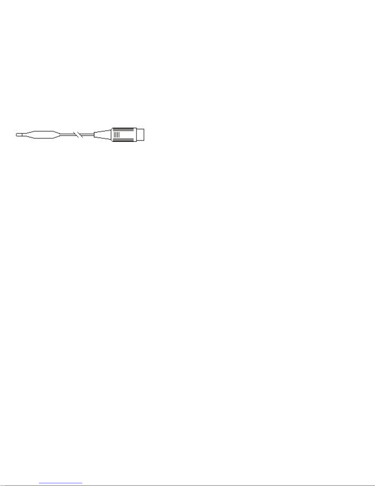
LogIT Voyager SX User manual


Contents
Acknowledgements 2
Introduction 3
Voyager Basics - Quick start guide 4
SmartEye sensor 6
HiTemp sensor 7
Using Voyager for live readings 8
Using Voyager for remote logging 7
Timing and counting with Voyager 10
Other Voyager functions 11
Troubleshooting 12
Experiments with Voyager 13
Voyager Experiments 14 - 43
Sensors and Cables for Voyager 44

2
Acknowledgements
Looking after Voyager
LogIT Voyager SX is designed as an educational tool and although durable it requires a reasonable degree of care which any electronic product
of this nature needs. Never plug anything into Voyager other than official LogIT Microsense®sensors and accessories. Please read the warning
guides throughout this book and in particular do not allow Voyager to get damp, wet or expose it to extremes of temperature or shock unless
instructions specifically state. If the unit is accidentally exposed to any of these conditions it could malfunction and serious damage result. In the
event of any problems remove the batteries immediately and seek advice. Always dispose of used batteries safely.
Safety and risk assessment
It is the responsibility of the user or teacher to have made suitable risk assessments before carrying out any student led experimentation. A
teacher has a duty of care towards their students to ensure experiments are carried out within a safe environment. The instructions and
experiment ideas contained within this manual highlight particular hazards but are not exhaustive and are not a substitute for your own
assessment. Refer to your science departments risk assessment criteria and apply accordingly.
Acknowledgements and Copyright
LogIT Voyager was developed and designed in Great Britain by Steve Cousins, Mark Finch, David Palmer, Andrew Rouse and Paul Watson. The
design team express thanks and acknowledgement to their family, friends, education and commercial colleagues for their support.
This manual was written and designed by Mark Finch and David Palmer.
Contents and concepts are copyright ©2006 DCP Microdevelopments Limited. The manual may be copied by the purchasing establishment for the
educational support of LogIT Voyager provided that original copyright and product acknowledgement is retained. Any other reproduction in whole
or part is prohibited without prior written permission from the publishers. LogIT and LogIT Voyager are trademarks of DCP Microdevelopments
Limited. All other trademarks acknowledged.
The manual was written and designed on Apple Macintosh G5 computers using Adobe Indesign.
LogIT Voyager SX is designed as an educational tool. The designers and manufacturers cannot be held liable for any special, incidental,
consequential, indirect or similar damages due to loss of data, loss of business profits, business interruption or any other reason resulting from the
use of LogIT products, even if they have been advised of the possibility of such damages. Not for use in life support applications. DCP accept no
responsibility for safety or risk assessment. Statutory rights are not affected.
First Edition March 2006 Published by DCP Microdevelopments Limited, Norfolk, Great Britain. www.logitworld.com
Electromagnetic compatibility declaration
The LogIT system and accessories are designed for use as education and training
equipment. “The use of this apparatus outside the classroom, laboratory, study area or
similar such place invalidates conformity with the protection requirements of the EEC
Electromagnetic Compatibility directive (89/336/EEC) and could lead to prosecution”.

3
Introduction to LogIT Voyager
LogIT Voyager SX was designed specifically for science at Secondary and College Levels.
It is based on the concept of the highly successful LogIT Explorer which we designed for Primary Schools, of which many thousands have now been
supplied and are in use around the world.
Research tells us that Explorer has been so popular because it is easy to use, has an appealing ergonomic shape and is supplied as complete with
sensors and experiments to get started straight out of the box. So we built on these features and introduced full compatibility with the comprehensive
range of LogIT Microsense®sensors which are designed for higher level science.
Because we want to offer lots of functionality in the basic set we also specially developed the versatile SmartEye, a directional light sensor which
detects both light level and can also measure time and speed for physics work, all using one sensor with no buttons or adjustments required - smart!
Voyager is available as both SX and SX Air versions, which integrates long range wireless bluetooth technology into the handset enabling even more
ambitious and exciting experiments to be undertaken.
The software which runs inside each unit can be upgraded easily using a free internet download so that as new sensors are released your Voyager can
be kept right up to date.
Like its Explorer brother, we defined Voyager’s content and functionality from the latest curriculum’s needs of a modern school science lab.
Voyager has been designed to meet most of the needs of Secondary education, be intuitive to use and realistically priced for education.
Now celebrating its 25th year, as ever DCP welcomes all feedback so that we can feed the real experience of users directly into our product
development which always endeavours to design innovative products which offer good value and are easy to use.
David Palmer
DCP Microdevelopments
March 2006

4
Voyager Basics
Voyager
Green Button
Starts logging or marks
an event
Blue Button
Help or Menu
USB socket
for connecting to computer
Holding eye
Thread a cord for
secure hand or belt grip
Red Button
Stops Logging or switches
off Voyager
Liquid crystal display showing
sensor readings, battery condition
and on-screen help
Sockets for LogIT
Microsense Sensors

5
!!!,+!,).%
!!!,+!,).%
!!!,+!,).%
!!!,+!,).%
1
• Turn Voyager over and carefully
remove the 5 case screws using the
small screwdriver supplied.
• Fit 4 AA batteries - ensure correct
orientation of all batteries (alkaline
or rechargeable recommended)
• Replace cover and carefully
tighten screws
FIT BATTERIES
Check orientation of each battery
Do not release any other screws
inside or touch any other parts
• Switch on Voyager by pressing any
button - live data from sensors is shown
on the display.
SWITCH ON & MEASURE
GREEN
Go / Yes
RED
Stop / No
BLUE
Help/Menu
TO REMOTELY RECORD DATA
• Press the Green button to start logging
(flashing [L]) and the red button to stop logging
2CONNECT COMPUTER
• Run Datalogging software on computer
• Connect Voyager to PC using USB cable
(or enable bluetooth link if using Voyager
Air)
• Select FETCH to retrieve stored data
(specific operation depends on software)
OR
• Select START to commence live logging
sensor readings on the computer screen
Voyager Basics - Quick Start
3
4 x AA
Batteries
∆

6
SmartEye sensor
This sensor was developed specifically for Voyager so that many different types of experiments can be performed using the standard pack. It is called
SmartEye because it is a versatile light sensor which adapts automatically to either measuring light level or timing events, depending on how you use it.
SmartEye is different from a conventional light sensor in several ways:
• It has a particularly focused field of view (just 20˚) so that just like a torch you can aim and measure quite accurately. Most light level sensors have a
very wide field of view of 150˚ or more, which is reasonable for measuring the average light levels of large areas (as a camera needs) but not very good
when you are trying to measure or compare light from a specific area, as you often need to do in science experiments. You will notice that the sensor
also incorporates a shroud to shield the detector from stray or incident light.
• SmartEye measures infrared (IR) as well as visible light. Although not sensitive enough to measure the infrared radiation from a radiator for example,
it can detect stronger sources from IR remote controls or the sun and you can use this ability to demonstrate the effectiveness of different materials
such as glass as insulators or filters. This makes it a versatile sensor to have in the lab, but always remember that it is also sensitive to infrared,
particularly when measuring colours using a strong source of light like a filament lamp which has a high content of infrared light (for colorimetry you can
use the new Colorimeter unit which is specifically designed for this function).
• The detector (called a PIN photodiode) inside SmartEye is a very fast reacting device and when used with the special software contained in Voyager
it enables the sensor to be used for measuring Time, Frequency, Counts etc. You do this by simply aiming a fairly bright light (eg window a torch) at
SmartEye and passing the object you wish to time or count in between the sensor and the light source, effectively breaking the beam - this is further
explained in experiments later in this book. This extra digital functionality is either automatically selected by the software you are using or you can
access using the Set up sensors option described later.
The SmartEye sensor reads directly in the range of 0 to 20,000 Lux, the standard SI unit of Light illuminance. Although this is a very wide range, on an
extremely bright sunny day the sensor can have too much light. But just as with human eyes, the level can be reduced using a filter (or sunglasses) to
cut down the light. Note that although it may be tempting to point the sensor straight at a source of light this is not generally good practice and could
cause serious damage if pointed at the sun. So, just as a photographer does with a light meter, the light sensor should be pointed at a surface or
‘target’so that you measure the reflected light - a white card is ideal.
Care
This sensor is robust but take care to protect it from excessive heat or light and never point any sensor directly at the sun. It is not waterproof so protect
from water, rain or high moisture.
Alternative sensors (also see page 44)
Other light level measuring sensors include the LUX sensor (which has eye response) and SPX LUX (very wide 100,000 Lux range). Other sensors for
time and speed measurements include Light gate, Reflective switch, Accelerometer and Ultrasonic Ranger sensors.

7
HiTemp temperature sensor
HiTemp is a general purpose temperature probe designed for measuring air, liquids (but not acids) and skin temperature within the range of -10°C to +
110°C with a 0.1°C resolution and a typical accuracy of better than 1˚C.
Due to its small size and low thermal mass, HiTemp has a fast response time and the sensor and cable are both lightweight and waterproof making it
suitable for suspending in air or liquid and also ideal for measuring low surface or skin temperatures with it’s small tip.
As with any sensor, if you need to measure with accuracy and repeatability you must carefully control the experiment conditions and consider the effect
of where and how the sensor is positioned. For example, if it is put into a beaker the sensor should not touch the glass walls and the liquid should be
repeatedly agitated to maintain even heat transfer around the sensor.
The distance HiTemp can be used away from Voyager can be extended using one of the Microsense extension cables but we recommend it is not
extended beyond 3 metres as this may introduce interference or inaccuracies.
Care
The HiTemp tip and cable are waterproof but the connecting plug (and socket) are not. The sensor uses a thin cable to make it very flexible and
versatile but you need to take care that the cable is not pulled, twisted or bent sharply as this could fracture wires inside - we suggest it is treated with
the same care as you would the flexible wires used for music player headphones. Also take care not to force the sensor into things like hard soil and
never expose it to strong acids or alkalis which could attack the plastic or stainless steel tip.
Do not expose the sensor to temperatures outside of its range - for example take special care if measuring the temperature in a heated pot or kettle
as the element is at a much higher temperature than the water and will damage the sensor if touched. HiTemp is not suitable for measuring the
temperature of anything over 110˚C maximum, including flames.
Alternative sensors (also see page 44)
For frequent experiments more suited to a longer solid probe style and which do not require such fast response times we suggest the LogIT
Microsense®ProTemp which has a strong 180mm long stainless steel probe and which can measure a wider span of temperature in the -30 to +130˚C
range with a 0.5˚ accuracy and 0.1˚ resolution. The ProTemp can plug directly into Voyager for hand held wire-free monitoring and can also be used
further away by using a sensor extension lead.
For higher temperature ranges such as ovens or even flames, a K-type thermocouple adapter is available which works with most of the different
styles of K-type thermocouples available and can measure temperatures from -50˚C to +1200˚C with a resolution of 1˚C, although bear in mind that
thermocouples are generally not as accurate as the precision thermistor devices used in HiTemp and ProTemp.

8
Using Voyager for live readings
Using Voyager as a meter
Although Voyager is primarily a datalogger, it can also be used as a versatile hand held meter, so that live readings from any LogIT sensor can be
viewed on the built in screen and so avoiding the need to have extra thermometers, sound meters etc.
• Meter mode
This mode is indicated on the Voyager screen by an Mand is the default screen when first switched on.
The screen will display Insert sensors until one or more LogIT Microsense sensors are plugged in, when it will change to display the sensor(s)
measuring units above the live actual reading from each sensor.
• Alternative sensor readings
Some sensors have extra functions or reading types other than the default; for example the SmartEye sensor defaults to reading Light level in Lux,
but can also measure digital (on and off) events like time or frequency. On many analogue sensors there is also an option to select Smooth or Fast to
change the response of a sensor reading from its default. Sometimes these other functions are automatically selected by what you ask the Voyager
or connected computer to do, but from Meter mode you can also select these functions by inserting the sensor then pressing the ?button until the
Setup Sensors option appears. You can then cycle through the various options available for that sensor using the ✘or ✔keys and press ?to select.
Once set the new setting will stay until Voyager switches off or until changed again using the Setup sensors option.
• Meter Stay on
To save battery power Voyager automatically shuts down after a few minutes. However if you are taking lots of readings you may wish to override
this to make the meter stay on. To do this switch Voyager on by pressing and holding down ✔button for more than 5 seconds. The Mwill now flash
indicating you have selected meter stay on function.
• Using Voyager with the Computer as a meter and datalogger
The Voyager and sensors can also be used to display their readings live on a computer, again effectively just as a meter. In this mode we are really
using Voyager as a sensor interface to convert the readings from the sensors into data which the PC can interpret and display using datalogging
software. Most datalogging software, including LogIT Lab, will do this very easily by just running the software, plugging Voyager in and selecting to
display live sensor readings as digits or moving bars etc. This can be a really useful facility for any experiments you want to perform at the front of a
class, especially when using a large screen.
You can also record these readings for live datalogging using the computer as storage - often called real time logging. You have to connect the
datalogger to the computer as above and then select Start to start recording readings and displaying them live as a graph, bars or table of results.
Refer to the datalogging software manual for more details on how to do this.
Of course if you have a Voyager SX Air Model you can log and display live data on the computer screen with no wires!
Insert sensors
M --- --- ---

9
Using Voyager for remote logging
LogIT Voyager can be used as a remote datalogger, which means it can record sensor data completely independently of and away from the computer.
It has three main datalogging options which all record sensor readings against time - this is in addition to time, speed and counting options which are
covered later. Note you can also Setup Sensors for different reading types as shown in previous section.
• AutoLog
AutoLog is probably the most often used datalogging option as it is so easy to use and is effective for most datalogging tasks.
To record using Autolog simply insert the sensors you wish to use, switch on and when ready press the ✔key! The flashing Lconfirms you are logging
and as this mode is completely automatic it will record from a few seconds to months without any setting up!
How does it do this? Autolog is based on the principal that a quick experiment requires fast logging for not very long but that a longer experiment
needs less readings. Of course when you press the ✔key it does not know how long your experiment is going to last, so at the beginning it starts
taking readings very fast and then if it carries on logging it gradually slows down. Of course you do not need to worry about any of this as it is all done
automatically by Voyagers microprocessor and all you will see is a complete set of results.
It is AutoLog that helps give LogIT its trademark simplicity of Green to Start and Red to Stop datalogging without any setting up.
• Setting your own log rate
Although AutoLog is good for most experiments there may be times when you want to choose a fixed time interval between logging readings. You can
do this easily by first inserting the sensors you will be using, selecting Set Log Rate then pressing ?and ✘or ✔keys to choose the best log rate for
your experiment - the maximum duration of the experiment is automatically displayed next to it.
Note that setting your own log rate also has the advantage that the experiment can use more memory and so stores more readings.
• Marking events
It can sometimes be useful to be able to mark a certain point in time to signify something you have seen or a change in conditions etc. You can add
Marks to your data by pressing the ✔button during logging. The screen will confirm that a marker has been stored and when you later download the
results you will see that pointers have been added at the times you Marked (on most datalogging software such as LogIT Lab).
• Snapshot logging
Both Autolog and Set Log Rate options both depend on Voyager controlling when readings are taken at regular intervals. But there may be times when
you want to control when readings are taken, such as taking readings at different points along a river for example. For this you can use Snapshot
logging which as its name suggests takes a reading from all sensors each time you press the ✔button - the display confirms the number of each
reading stored. You can enter Snapshot logging from using the ?key in the usual way.
• Saving Power
During long datalogging sessions the Voyager is not doing much except keeping a track of time and taking occasional readings.
Like many electronic devices the display takes quite a lot of power so after a while Voyager switches off its screen to save battery power. If you left
Voyager logging and the display is off you can check readings etc at any time by pressing any button once.
Lux oC
L 1360 20.4 ---

10
Timing and Counting with Voyager
The previous section dealt with logging sensor readings over time.
But Voyager can also be used to time and count single and multiple events to derive different data, frequently used in Physics but some functions are
useful in other fields as well, like counting.
In our context we refer to an event as a change in sensor value. Normally these are digital sensors like push buttons or light gates which have just two
states, on or off. But Voyager can also use some analogue level sensors as event triggers, the best example being SmartEye which can be used both
as an analogue light level sensor or digital timing sensor.
This section deals with the digital and timing related functions built into Voyager, but note that you can also do much more with timing using Voyager
connected up to a computer running datalogging software such as LogIT Lab.
• Measuring Time with Voyager
Voyager can measure and display the amount of time between 2 events from one or more sensors.
Insert the sensor(s) you are going to time with and then press ?until measure time is displayed.
This screen shows two time displays, old time, new time and ooo (sensor levels). Timing is a digital (on/off) event and the ooo shows what levels the
Voyager is seeing so making it easy to set sensors up. So if you are using the SmartEye sensor for example you can point it at a light source and break
the light beam to start or stop timing.
Voyager starts and stops timing when the input level changes from one level to another - you can also use the ✔key to manually start and stop timing,
helpful when setting up and also for use as a simple stopwatch! You can leave timing mode by pressing ✘.
• Measuring Speed with Voyager
Voyager has a built in facility to measure speed directly when used with the specified 20cm card. It calculates the speed by timing how long it takes for
a known width of card (in Voyager’s case 20cm) to pass through a light path to calculate the speed (in metres per second). Although primarily designed
for SmartEye it can also be used with other sensors such as Light gates. You can use the ✔key to manually start and stop timing (helpful when setting
up). To leave Speed mode press ✘.
• Counter
Voyager has a built in counter which increments on an event, such as a light beam being broken or the ✔key being pressed. A simple function but
with the right sensor setup can be useful to count a ball bouncing, bubbles, even birds through a bird box.........!
You can also attach one or more Push switch sensor(s) to use it as a manual push button counter. To leave Counter mode press ✘.
The timing facilities built into Voyager are enhanced when it is used with a computer running timing software, such as LogIT Lab, because a much
wider range of advanced facilities are possible including acceleration, SHM, Kinetic Energy, etc.
The experiment guide later in this handbook shows examples of investigations using timing facilities of Voyager.
Old New ooo
0.020 0.025 s

11
Other Voyager functions
• Security Stamp
You can enter your school name, postal code or datalogger reference etc (to help uniquely identify and check-in each one) so that it appears each time
Voyager is switched on. As you will only want to change it occasionally, it is programmed via the computer using the LogIT software and to prevent it
being abused with unwanted words etc details are supplied with the software, usually on the license paperwork which is normally stored safely away.
• Power
Voyager can be powered in two ways, Internal batteries or USB.
Internal batteries can be alkaline or rechargeable types. Rechargeables are not charged by USB because this could also try to charge alkaline batteries
if fitted which would be dangerous. Other types of non-alkaline zinc carbon batteries (eg zinc carbon) are NOT suitable as they are not able to supply
enough power for Voyager and its sensors. Battery life will depend on how often you use Voyager and which sensors you use with it, but in an average
school we would expect a set of 4 alkaline batteries to last 9-12 months. Note that if you decide to use rechargeable batteries that they will naturally
discharge after around 3 months or so even if Voyager has not been used, so Alkaline batteries may be the most convenient cells to use. Unusually
Voyager can actually be fitted with just 2 batteries instead of 4, although it will last less than half the length of time of 4 which is why we fitted double
holders. Nevertheless this feature may be useful if you only had 2 batteries available some time or need to make Voyager as light as possible for travel
etc. If only fitting 2 cells you must fit them next to each other and ideally in the lower part of the handle as this will make it more balanced to hold.
When you connect Voyager to a computer it is powered by the USB port which automatically takes over from the built in batteries so preserving battery
life (assuming the port is able to deliver the power required - some portable computers can only supply a small amount of power from their USB ports).
Most LogIT sensors are low power, notable exceptions being Light gates, Colorimeter, Pulse Monitor and the DO2 probe. Fortunately most of these
sensors are used on benches so where possible connect Voyager to the computers USB port to preserve battery life.
Just as with consumer products such as mobile phones, Bluetooth unfortunately takes a considerable amount of power so if you are using a Voyager
Air model make sure you switch Bluetooth off except when you are using it - more details are in the Voyager Air instructions.
• Setting up Sensors
Voyager allows Microsense®sensors to record alternative data from their default readings. This is a useful feature which allows such data as RPM to
be directly recorded from a digital sensor such as a light gate. To access this feature, plug a Microsense®sensor(s) into Voyager and press the ?button
until ‘set up sensors’is displayed. Pressing ✔then allows the options shown below to be cycled and selected.
• 0 or 1 - Can be used with Microsense®digital sensors which are on or off and also some analogue sensors which have a threshold level.
• Counts - Used to count up to 254. For example, a SmartEye sensor and a torch could allow the counting of people through a door.
• Hz - Display’s the frequency that the sensor is changing state. Can be used with both digital and analogue sensors.
• PerMin - A rotating object’s RPM can be displayed. Can be used with both digital and analogue sensors.
• Period - Used for manual calculations of speed. Can be used with both digital and analogue sensors.
• Fast - Used to take quick readings from the Microsense®sensor. Used when quick changes need to be captured, such as an accelerometer.
• Slow - Gives a smoother graph. Useful looking at small changes such as barometric air pressure or to smooth out variations such as flickering lights.
To cancel the selected setting, simply press ✘- the Voyager and sensor readings return to their original default type when next used.
< Security stamp:>
<Your name here>

12
Troubleshooting
Problem
I have fitted four batteries but nothing happens on the display when I
press any of the Voyager buttons.
Voyager forgets the time when disconnected from USB.
Sometimes when I am running a long experiment with Voyager
graphing Live on my computer it stops logging.
I wish to use Voyager as a hand held meter but the display
automatically turns off after a while - can I keep it on?
Using Autolog after a few minutes the Voyager screen turns off.
My Voyager seems to be doing some odd things but my batteries are
OK - can I reset the Voyager?
Solution
Remove and check that all batteries are fitted correctly as shown
in the battery holders. They must all be the same type and either
charged Rechargeable types or new Alkaline batteries - other lower
power batteries such as Zinc Carbon types will not work properly
and must not be used
Voyager can be powered from the USB port of a computer without
the need for batteries to be installed. However if this is done when
Voyager is disconnected the clock is no longer powered and so the
time is reset.
Some computer ‘screen savers’can interrupt continuous
datalogging, so we suggest screen savers are turned off.
Keep the meter display on by pressing and HOLDING green button
on for more than 5 seconds when switching on .
This is normal. See Saving Power on page 9.
To fully reset Voyager, remove all batteries, wait for around 10
seconds and then refit batteries while holding the blue button down
- Voyager should now fully reset.

13
Experiments with Voyager
Introduction to Experiments
The experiments included in this manual have been designed for use
with the HiTemp temperature and SmartEye sensors supplied with
Voyager. They can also be performed using other LogIT Microsense®
sensors such as the ProTemp, LUX sensor or Light gate.
The experiments are designed to provide an understanding of how
Voyager can be used within science lessons to teach science based
practicals that follow the national curriculum. These experiments
could also be adapted to form part of the science coursework for the
UK GCSE requirements or used simply as the basis for investigative
work within a science framework.
The experiments are only a small fraction of what is possible with the
LogIT Voyager and by using additional sensors as listed on page 44,
the Voyager can be built into a very powerful datalogging tool.
The experiments have been written from the teachers perspective
and can be adapted for the abilities of the pupils as well as providing
a basis for the development of work sheets if required.
As secondary school teachers tend to be science specialists, the
experiments are left fairly open ended. This was deliberate to allow
teachers to refine the resource to their own teaching style or to
integrate easily into departmental schemes of work.
Details of how to set up the datalogging software for each experiment
can be found in the manual supplied with the software. Hence, each
experiment details how to connect Voyager and what the software is
required to measure.
Subject contents Page
Physics
Simple Harmonic Motion 14
Friction 16
F=Ma 18
Cooling by evaporation 20
Where does the heat go? 22
Chemistry
Endothermic reactions 24
Cooling curves 26
Rates of reaction 28
Combustion of fuels 30
States of matter 32
Biology
The sun as a source of heat & light 34
The greenhouse effect 36
Energy in food 38
Simple physiology 40
Soil temperature analysis 42

14
Simple Harmonic Motion
Subject: Physics
Sensor: SmartEye sensor
Aim: To show how the length of a pendulum affects the Time Period.
Overview:
The Time Period is the time taken for a pendulum to swing from one side to the other and back again. By keeping the mass of the pendulum bob
constant, the length of the pendulum can be altered and the time period measured.
Equipment required: LogIT Voyager.
1 SmartEye light sensor.
Matt black card.
Light source such as torch, lamp or similar.
Mass and holder (could be modelling clay).
String to make pendulum.
Clamp stands.
Hazards:
Children should be supervised at all times.
If clamp stands are used to hold the pendulum, make sure they are not mounted above pupils.
Always check your local regulations or the school advisory service such as CLEAPSS or SSERC
for guidance on the use of any hazardous material or source.
Setup:
1. Set up a 2m length of string and attach the mass to the end.
2. Make a small tube of black card by wrapping a small slip of card around a pencil such that the
width is at least the width of the SmartEye sensor. (Approx. 1cm diam.)
3. Place the tube over the pendulum and place Voyager such that the SmartEye is close to the swinging tube. (See photo).
4. Place the light source opposite the SmartEye sensor forming a light ‘gate’.
5. Connect Voyager to the computer, start the datalogging software, select the timing function and select ‘Simple Harmonic Motion’.
Note: The Voyager can be used with a clamp stand or simply placed on text books. If using clamp stands, do not clamp Voyager too tightly.
Ensure that the light source shines into the SmartEye as this change in contrast between the light source and black card will allow Voyager to
‘see’ the card passing.

15
Method:
1. Hold the pendulum bob to one side of the SmartEye sensor.
2. Release the pendulum and allow the pendulum to swing a minimum of 10 times.
3. Note the time period.
4. Repeat for various length of pendulum.
5. When finished the results can be printed, saved or transferred to a spreadsheet for more analysis.
Note: Make sure that the pendulum only swings a small amount to prevent the premature degradation of the time period.
If you obtain some strange results, this can usually be attributed to a false trigger of the light ‘gate’. This can happen if a hand or
other object inadvertently passes through the gate. You can also get false triggers if the ambient light changes suddenly, for
example bright sunlight falling on the sensor part way through an experiment.
Results:
What effect does the change in length of a pendulum have on the time period?
What variables might affect the time period?
Why are the oscillations kept small?
What factors do you think may have contributed to any incorrect results?
What would you do to improve the accuracy of the experiment?
Was it a fair test?
Going further:
What effect does adding mass have on the time period?
Pupils could test the relationship T = 2 π√(l/g) for a simple
pendulum.
Investigate the time period of a spring. How might they differ?
Physics

16
Friction
Subject: Physics
Sensor: SmartEye sensor
Aim:
To test the effect of friction on the speed/time of a ‘vehicle’ travelling down a ramp.
Overview:
The choice of using speed or time is partly dependent on the abilities and knowledge of the pupils. Because only one SmartEye sensor is used a known
length of card is required so that the speed can be calculated. The Voyager starts timing when the front edge of the card passes the sensor and stops
timing when the back edge passes i.e. it times how long it takes the card to pass in front of the sensor. By knowing the length of the card and how
long it took to pass, the speed can be calculated.
Equipment required: LogIT Voyager.
1 SmartEye light sensor.
Dynamics trolley, toy car or similar.
20cm matt black card.
Light source such as torch, lamp or similar.
Test track which can be raised to form a ramp.
Different materials to be placed on the track.
Hazards:
Children should be supervised at all times
Ensure the datalogger cannot come into contact with water or damp.
Always check your local regulations or the school advisory service such as CLEAPSS or
SSERC for guidance on the use of any hazardous material or source.
Setup:
1. Cut out a 20cm long piece of matt black card and attach it to the test vehicle.
2. Place the Voyager about three quarters of the way down the track ensuring the card passes in front of the SmartEye sensor.
3. Place the light source opposite the SmartEye sensor forming a light ‘gate’.
4. You can record readings remotely using Voyager’s menu (blue button) or LIVE whilst connected to the computer. If using remotely, press
Voyagers Blue button and select ‘Speed’ (or ‘Time’ if preferred) then press the Green button. If using a computer, connect Voyager to the
computer, start the datalogging software and select the timing function. Set up the software so that it knows you are using a single light
‘gate’.

17
Note: The Voyager can be used with a clamp stand or simply placed on text books. If using clamp stands, do not clamp Voyager too
tightly. Ensure that the light source shines into the SmartEye as this change in contrast between the light source and black card will
allow Voyager to ‘see’ the card go past.
Method:
1. Run the vehicle down the ramp passed Voyager without a material on the ramp’s surface. (Does the ramp’s surface count?)
2. Choose a piece of material and write down its description. Place it securely onto the ramp’s surface.
3. Run the vehicle down the ramp again.
4. Repeat this for each piece of material.
5. When finished the results can be printed, saved or transferred to a spreadsheet for more analysis.
Note: If you obtain some strange results, this can usually be attributed to a false trigger of the light ‘gate’. This can happen if a hand
or other object inadvertently passes through the gate. You can also get false triggers if the ambient light changes suddenly, for
example bright sunlight falling on the sensor part way through an experiment.
Results:
There are a number of factors which affect the outcome of this experiment and can be used to form the basis of a ‘fair test’ discussion
relating to the results. For example, the height of the track, starting point of the vehicle or whether the vehicle is pushed or
simply released.
Was the method chosen a fair test?
Which material slowed the vehicle the most (largest friction)?
Which material slowed the vehicle the least (smallest friction)?
Going further:
What effect would different size tyres have on the results.
Does the mass of the vehicle change the results?
Does the shape of the vehicle affect the outcome?
How does the angle of the ramp affect the results?
Physics

18
F=Ma
Subject: Physics
Sensor: SmartEye sensor
Aim: To prove that Force is derived from the Mass of an object multiplied by the objects acceleration.
Overview:
For this investigation, the acceleration of an object will be recorded and noted along with the Force applied. Then by plotting a graph of Force against
Acceleration, a straight line graph of gradient equal to the Mass of the object should be obtained.
Equipment required: LogIT Voyager.
1 SmartEye light sensor.
Air track car, dynamics trolley, toy car or similar.
Matt black 29 x 5 cm card and string.
Light source such as torch, lamp or similar.
Air track with mounted pulley or dynamics track.
Slotted masses and holder. (5 or 10 gram masses)
Hazards:
Children should be supervised at all times.
Ensure the datalogger cannot come into contact with water or damp.
A set of soft cloths in a box might be used to catch the mass as it falls to prevent personal injury.
Always check your local regulations or the school advisory service such as CLEAPSS or SSERC for
guidance on the use of any hazardous material or source.
Setup:
1. Fold in half the black card and measure 14 cm from the non folded end and cut out a square
about 2 cm deep. Attach it to the test vehicle. (See photo)
2. Place the Voyager just in front of the interrupt card ensuring the card passes in front of the
SmartEye sensor.
3. Place the light source opposite the SmartEye sensor forming a light ‘gate’.
4. Connect a piece of string to one end of the vehicle and attach the mass holder to the other passing over a pulley or bench edge.
5. Connect Voyager to the computer, start the datalogging software, select the timing function and select ‘Acceleration’. Set up the
software so that it knows you are using a single light ‘gate’ and the length of the card is 14 cm.
Table of contents