Deviser E7000 Series User manual

User Guide
E7000 Series Cable & Antenna Analyzer
!
!
Ver
!
1.19
Model
E7000A
E7000A-SA
E7100A
E7100A-SA
Cable&Antenna
Analyzer
4.4GHz
4.4GHz
6.1GHz
6.1GHz
Spectrum
Analyzer
3GHz
3GHz
Transmission
Analyzer
3GHz
3GHz


E7000 Series Cable & Antenna Analyzer User Guide
- 1 -
Conventions
This manual has the following conventions for presenting information.
WARNING: A warning alerts you to any condition that could cause personal
injury.
CAUTION: A caution alerts you to any condition that could cause a
mechanical failure or potential loss of data.
Make sure the AC power supply voltage meet the equipment requirements,
otherwise it will cause a equipment failure.
Make sure to plug the power cable into an electrical outlet that has a safety
grounding before turning on the power switch.
Touch the internal circuit may cause a mechanical failure or personnel injury,
so only trained engineer can remove the instrument cover and maintain the
instrument.
Guarantee
This instrument is guaranteed for a period of 12 months from the date of
shipment. Under warranty, any fault not caused by improper use will be
repaired for free.
Liability of the user: Use this instrument according to this instruction manual.
When
this instrument need to be repaired, please send it back to our company or
our appointed repair center.
The guarantee is limited only to the instrument and does not involve any
damage of
equipment, personnel and property caused by improper use of the
instrument.

E7000 Series Cable & Antenna Analyzer User Guide
- 2 -
Limitation of Guarentee
The warranty is not applicable for the faults resulted by improper use or
inadequate maintenance (including software or interface), and unauthorized
open of the instrument. Within the 12 months warranty period, calibration,
maintenance service and consultation shall be free. After the 12 months
warranty period, fees for material and repair workman will be charged
appropriately.
The following items are not under warranty:
A. Damage caused by improper voltage input.
B. Deformation or damage of panel, switches, devices and case as well as
defects involving interval parts caused by external mechanical force
(shocking and dropping, etc.).
C. Defects caused by unauthorized repair.
D. Defects caused by the instrument worked beyond the required technology
specification.
Updates
Updates, if any, can be downloaded from the Deviser web site
at:http://www.deviserinstruments.com
Deviser Part No.: DK11820E7000
© Tianjin Deviser Electronics Instrument Co., Ltd.
All rights reserved.
Printed in CHINA. May 2012.

E7000 Series Cable & Antenna Analyzer User Guide
- 3 -
Table of Contents
1 General Information ............................................................................. 1
1.1 Introduction ......................................................................................... 2
1.2 Available Models .................................................................................. 2
1.3 Available Options ................................................................................. 3
1.4 Standard Accessories ........................................................................ 3
1.5 Preventive Maintenance ...................................................................... 4
1.6 Calibration Requirements&Annual Verification ................................... 4
1.7 ESD Caution .......................................................................................... 4
1.8 Battery Replacement ........................................................................... 5
1.9 Soft Carrying Case ................................................................................ 6
2 Instrument Overview ........................................................................... 7
2.1 Turning On the instrument .................................................................. 8
2.2 Front Panel Overview ........................................................................... 9
2.3 Test Panel Connector Overview ......................................................... 13
2.4 Display Overview ................................................................................ 15
2.5 Menu Operation ................................................................................ 16
2.6 Symbols and Indicators ...................................................................... 18
2.7 Data Entry .......................................................................................... 20
2.8 Mode Selector Menu ......................................................................... 20
3 Quick Start Guide ................................................................................ 22
3.1 Introduction ....................................................................................... 22
3.2 Cable & Antenna Analyzer mode ....................................................... 22
3.3 Spectrum Analyzer ............................................................................. 26
4 File Management ................................................................................ 31
4.1 Introduction ....................................................................................... 31
4.2 Managing Files ................................................................................... 32
4.3 File Menu Overview ........................................................................... 34
4.4 File Menu ........................................................................................... 35
4.5 Recall Menu ....................................................................................... 36
4.6 Copy Menu ......................................................................................... 37
4.7 Delete Menu ...................................................................................... 38

E7000 Series Cable & Antenna Analyzer User Guide
- 4 -
4.8 Files type ............................................................................................ 39
5 System Operations .............................................................................. 40
5.1 Introduction ....................................................................................... 40
5.2 System Menu Overview ..................................................................... 40
5.3 System Menu ..................................................................................... 42
5.4 System Options Menu ........................................................................ 43
5.5 Display Setup Menu ........................................................................... 45
5.6 System Test Menu .............................................................................. 47
5.7 System Upgrade Menu ...................................................................... 48
5.8 Help Menu ......................................................................................... 49
5.9 Print Menu ......................................................................................... 51
5.10 Select Printer Menu ........................................................................... 52
6 Software Tool ...................................................................................... 53
6.1 Introduction ....................................................................................... 53
6.2 Feature Overview ............................................................................... 53
6.3 Install Site Workbench ....................................................................... 54
6.4 Connecting to the Instrument ............................................................ 54
7 Specifications ...................................................................................... 55
7.1 Cable & Antenna Analyzer ................................................................. 55
7.2 Spectrum Analyzer ............................................................................. 56

E7000 Series Cable & Antenna Analyzer User Guide
1
1 General Information
This chapter provides information about the following items.
● Introduction
● Available Models
● Available Options
● Standard Accessories
● Preventive Maintenance
● Calibration Requirements&Annual Verification
● ESD Caution
● Battery Replacement
● Soft Carrying Case
● Technical Support and Service Information

E7000 Series Cable & Antenna Analyzer User Guide
2
1.1 Introduction
E7000 Series Cable & Antenna Analyzer with integrated spectrum analyzer ,
reduces per site maintenance expense, maximizes system up-time, and
breaks away from the traditional fix-after-failure maintenance mode by
finding small problems before major failures occur. E7000 Series performs
various RF measurements aimed at simplifying cable feedline and antenna
analysis: Return Loss, SWR, Cable Loss, Distance-to-Fault (DTF), 1-port phase
and smith chart.
The E7000 is an integrated multi-functional analyzer that eliminates the need
to carry and learn multi instrument. The E7000 is a cable & antenna analyzer
that can be configured to include 3 GHz spectrum analyzer, 2-port
Transmission Measurement with a bias tee, and a High Accuracy GPS receiver
for location stamping.
The bright 6.5-inch color display provides visibility even in broad daylight.
Built-in Li-Ion battery can work more than 4.5 hours. Even with “spectrum
analysis” option, the working time is still more than 3 hours.
The internal 1G flash memory is large enough to store approximately 2,000
traces or setup files. Measurements data and setup files can also be stored in
a USB flash disk or transferred to PC via the LAN cable.
Site Workbench, a PC based software program, provides a simple and easy
way to manage, archive, analyze and print measurement reports, customize
your cable list, antenna list and signal standards list .
1.2 Available Models
Table1-1 lists the E7000 models and frequency ranges described in this User
Guide.
Model
E7000A
E7000A-SA
E7100A
E7100A-SA
Cable&Antenna
Analyzer
4.4GHz
4.4GHz
6.1GHz
6.1GHz
Spectrum Analyzer
3GHz
3GHz
Table 1-1. Available Models

E7000 Series Cable & Antenna Analyzer User Guide
3
1.3 Available Options
E7000
E7100
Description
E7000-0010
E7100-0010
Transmission Measurement
E7000-0030
E7100-0030
GPS receiver(Including antenna)
Table 1-2. Available Options
1.4 Standard Accessories
.Part Number
Description
E7000-0100
User Guide
E7000-0110
Quick Guide
C50N-P
N(male) type standard calibration kits
NP-DL01-NJ-150
1.5m N(male)-N(female) type RF cable
E7000-0200
CD : Site Workbench Software
E7000-0300
11.1V /5.2Ah Rechargeable Li-Ion Battery
PW31188821Q
FSP065-R AC Adapter
E7000-0400
Vehicle charger
,
E7000-0500
USB A/5-pin mini-B Cable
P. 3 1 0 0 1 5 0 0 0
Crossover LAN cable
E7000-0600
Soft Carrying Case
P. 1 1 0 8 2 9 N J K
L29(female)-N(male) Adapter
Table 1-3. Standard Accessories

E7000 Series Cable & Antenna Analyzer User Guide
4
1.5 Preventive Maintenance
E7000 series preventive maintenance include the unit surface cleaning, RF
connectors and all accessories cleaning. Clean unit surface with a soft,
lint-free cloth dampened with water.
NOTICE
:
To avoid damaging the display or case, do not use solvents or
abrasive cleaners.
Clear the RF connectors and center pins with a cotton swab dampened with
denatured alcohol. The fingers of the N(f) connectors and the pins of the N(m)
connectors should be unbroken and uniform in appearance. If you are unsure
whether the connectors are undamaged, gauge the connectors to confirm
that the dimensions are correct. The test port cable should be uniform in
appearance, and not stretched, kinked, dented, or broken.
1.6 Calibration Requirements&Annual Verification
Local service centers are responsible for instrument maintenance and
calibration once a year. To ensure performance conformity.Deviser
recommends a periodical maintenance and calibration.
The Cable & Antenna Analyzer is calibrated with OPEN, SHORT, LOAD
calibration components. It is especially important to verify the OSL
calibration components periodically to ensure performance conformity.
1.7 ESD Caution
E7000 series, like other high performance instruments, is susceptible to
electrostatic discharge (ESD) damage. Coaxial cables and antennas often
build up a static charge, which may damage the E7000 input circuitry.
E7000 operators must be aware of the potential for ESD damage and take all
necessary precautions.
It is recommended to discharge the static by connecting a short or load
device to the cable or antenna before connecting them to E7000. It is
important to remember that the operator may also carry a static charge that
can cause damage. Following the practices outlined in the above standards
will ensure a safe environment for both personnel and equipment.

E7000 Series Cable & Antenna Analyzer User Guide
5
1.8 Battery Replacement
The battery can be replaced without the use of any tool. The battery
compartment is located on lower side of rear (when you are facing the
measurement display). Wring out two screws, slide the cover down and
remove the battery. Installation is the opposite of removal.
NOTE
:
When inserting the battery, the battery label should face the back of
the instrument and the guide slot on the battery should be below the
contacts. If the battery door does not latch ed, the battery may be inserted
incorrectly.
Figure1-1. Battery Compartment Door
NOTE
:
Use only batteries, adapters, and chargers provided with this
instrument.
CAUTION
:
When using the Vehicle charger, Make sure that the supply is
rated for a minimum of 60 Watts at 12 VDC, and the socket is clean without
any dirt or debris. If the adapter plug becomes hot to the touch during
charging, Please discontinue use immediately.
NOTE
:
Deviser recommends removing the battery for long-term storage of
the instrument.
E7000 Series Cable & Antenna Analyzer User Guide
6
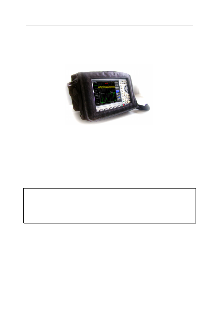
1.9 Soft Carrying Case
The E7000 can be operated while in the soft carrying case. On the back of the
case is a large storage pouch for accessories and power supply.
Figure1-2. Instrument Inserted into the Soft Carrying Case
To install the instrument into the soft carrying case:
1. The front panel of the case is secured with hook-and-loop fasteners. Fully
close the front panel of the case. When closed, the front panel supports the
shape of the case while you are inserting the E7000.
2. Place the soft carrying case face down on a stable surface, with the front
panel fully closed and laying flat.
NOTE
:
The soft case has two zippers near the back. The zipper closer to the
front of the case opens to install and remove the instrument. The zipper
closer to the back of the case opens an adjustable support panel that can be
used to provide support for improved stability and air flow while the
instrument is in the case. This support panel also contains the storage pouch.
3. Open the zippered back of the case.
4. Insert the instrument face down into the case, take care that the
connectors are properly situated in the case top opening. You may find it
easier to insert the connectors first, then pull the corners over the bottom of
the E7000.

E7000 Series Cable & Antenna Analyzer User Guide
7
2 Instrument Overview
This chapter provides a brief overview of the E7000 Series Cable & Antenna
Analyzer. The intent of this chapter is to acquaint the user with the
instrument. For detailed measurement information, refer to a specific
measurement guide listed in “Measurement Guides”.
This chapter provides information about the following items
● Turning On the instrument
● Front Panel Overview
● Test Panel Connector Overview
● Display Overview
● Symbols and Indicators
● Data Entry
● Mode Selector Menu
E7000 Series Cable & Antenna Analyzer User Guide
8
2.1 Turning On the instrument
The Deviser E7000/E7100 models are capable of approximately 4.5 hours and
the E7000SA/E7100SA models are capable of approximately 3 hours of
continuous operation from a fully charged, field-replaceable battery.
The E7000 Series can also be operated from a 12 Vdc source (which will also
simultaneously charge the battery). This can be achieved with either the
AC-DC Adapter or Automotive Cigarette Lighter Adapter .Both items are
included with the instrument.
CAUTION
:
When using the Vehicle charger, Make sure that the supply is
rated for a minimum of 60 Watts at 12 VDC, and the socket is clean without
any dirt or debris. If the adapter plug becomes hot to the touch during
charging, Please discontinue use immediately.
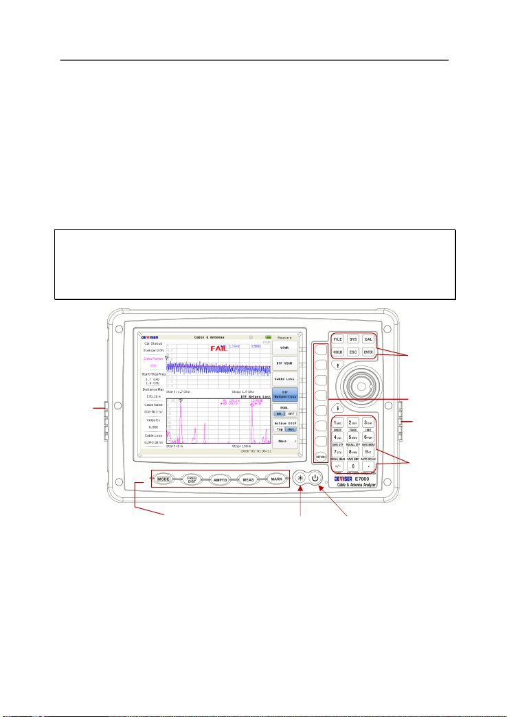
Main Menu Keys Backlight Control On/Off Button
Figure 2-1. E7000 Overview
To turn on the instrument, press the red On/Off button for 2s on the front
panel (Figure2-1). The instrument takes approximately twenty seconds to
complete power warm-up and to load the application software. At the
completion of this process, the instrument is ready for use.
Main Function
Keys
Numeric Keypad
/Measurement
function Keys
Sub-Menu
Keys
Fan Inlet Port
Fan
Exhaust
Port

E7000 Series Cable & Antenna Analyzer User Guide
9
2.2 Front Panel Overview
The E7000 Series menu-driven interface is easy to use and requires little
training. The E7000 uses the keypad for data input. The five main menu keys
below the screen and eight submenu keys on the right side are menu keys.
Function keys on the right, consist of six main function keys and twelve
measurement function keys.The twelve measurement function keys are dual
purpose, depending upon the current mode of operation.The dual-purpose
keys are labeled with a number on the key itself and the alternate function is
printed in black below each of the keys. Numeric keys are active in
parameter edit mode, otherwise measurement function keys are active .
Note
:
Keep the fan inlet and exhaust ports clear of obstructions at all times
for proper ventilation and cooling of the instrument.
Main Menu Keys
Five main menu keys are below the display screen.
Press the key then select a measurement mode by pressing the
corresponding sub-menu key.
NOTE
:
Available mode selections will vary according to model number and
options installed.
Displays the Frequency or Distance to Fault soft key menus depending on the
measurement mode.
Displays the amplitude soft key menu for the current operating mode.
Displays the measurement soft key menus for the current operating mode.
Displays the marker soft key menus for the current operating mode.
MODE
FREQ/DIST
AMPTD
MEAS
MARK

E7000 Series Cable & Antenna Analyzer User Guide
10
Sub-Menu Keys
There are eight keys that change function depending upon the current mode
selection. The current key function is indicated in the soft key menu area on
the right side of the screen.
Main Function Keys
There are six main function keys on the top of the panel.
Active the file management function to use for saving or recalling the setup
files, measurement files and graphics files.
Allow selection of system and application setup parameters, the display
language , system upgrade and printing etc..
Starts the calibration in SWR, Return Loss, Cable Loss, or DTF measure -ment
modes (not available in Spectrum Analyzer or Power Meter modes).
When in the Hold mode, this key starts the E7000 sweeping and provides a
Single Sweep Mode trigger; when in the Continuous mode, it pauses the
sweep. When in the Hold mode, the hold symbol appears on the display.
Exits the present operation or clears the status window. If a parameter is
being set, pressing this key will clear the value currently being entered and
restore the last valid entry. Pressing this key again will close the parameter.
Press this key to finalize data input or select a highlighted item from a list.
FILE
SYS
CAL
HOLD
ESC
ENTER

E7000 Series Cable & Antenna Analyzer User Guide
11
Measurement Function Keys
Measurement function keys are active when the instrument is not in
parameter edit mode.
Press this key to set sweep type, points, RF immunity, RBW, data averaging
and data smoothing etc.
Manipulating the trace menu enables you to find the difference between the
active trace and a saved trace or to do data math,etc.
Display the limit line menu for the current operating mode when in cable and
antenna analyzer or spectrum analyzer mode.
Save the current system setup to an internal memory location. When the key
is pressed, a Setup File Name appears. Use the numeric keys to enter
characters for the setup file name and press the ENTER key to implement.
Recall a previously saved setup from a memory location. When the key is
pressed, a Setup File selection box appears on the display. Select a setup
using the Up/Down arrow key and press the ENTER key to implement.
Save displayed traces to memory. When the key is pressed, the
Measurement File Name appears. Use the numeric keys to enter characters
for the measurement file name and press the ENTER key to save the trace.
Recall a previously saved trace from memory. When the key is pressed, a
Measurement File selection box appears on the display. Select a trace using
the Up/Down arrow key and press the ENTER key to implement.
SWEEP
TRACE
LIMIT
SAVE STP
RECALL STP
SAVE MEAS
RECALL MEAS

E7000 Series Cable & Antenna Analyzer User Guide
12
Implement the VSWR measurement.
Implement the RETURN LOSS measurement.
Implement the CABLE LOSS measurements.
Implement the DTF–VSWR measurement.
Implement the DTF–Return Loss measurement.
“↑ ↓” Arrow Keys
The arrow keys can often be used to change a value or to change a selection
from a list. This function is similar to the function of the rotary knob. The
arrow keys are also used to move markers.
Rotary Knob
Turning the rotary knob changes numerical values, scrolls through selectable
items from a list, and moves markers. Values or items may be within a dialog
box or an edit window. Pressing the Rotary Knob is used as “ENTER” key.
Number Keypad
The Number keypad has two functions: The primary function is number entry.
The secondary function of the number keypad is to list various menus or to
implement various measurements.
LED Indicators
Charging LED, is located on the test panel, the LED is red when the battery is
charging and is green when the battery is fully charged.
The Power LED, is located to the right of the On/Off key, the LED is green
when the unit is on.
VSWR
RETURN LOSS
CABLE LOSS
DTF VSWR
DTF RL
E7000 Series Cable & Antenna Analyzer User Guide
13
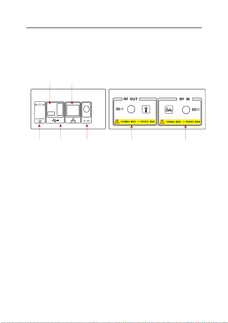
2.3 Test Panel Connector Over view
The connectors and indicators located on the test panel (Figure 2-2) are
listed and described below.
USB Mini-B Type LAN port
External USB A-Type DC Out RF Output RF Input
Power Supply
Figure2-2 E7000 Test Panel Connector
External Power
The external power connector is used to power the unit and for battery
charging. Input is 12.5 VDC to 19 VDC at up to 3.42A.
USB Interface - Type A
The E7000 has a Type A USB connectors that accept USB Flash Memory
devices for storing measurements, setup data, and screen images, or a GPS
modual.
USB Interface - Mini B
The USB 2.0 Mini-B connector can be used to connect to a PC.
LAN port
The LAN port is used to connect to a PC loaded the Site Workbench software
providing a simple and easy way to manage, archive, analyze, print
measurement reports, customize your cable list, antenna list, signal
standards list.

E7000 Series Cable & Antenna Analyzer User Guide
14
RF In
50ΩType-N female connector. Maximum input is +30 dBm at ±50 VDC.
RF Out/Reflection In
RF output, 50Ωimpedance, for reflection measurements. Maximum input is
+25 dBm at ±50VDC.
This manual suits for next models
8
Table of contents
Other Deviser Test Equipment manuals


