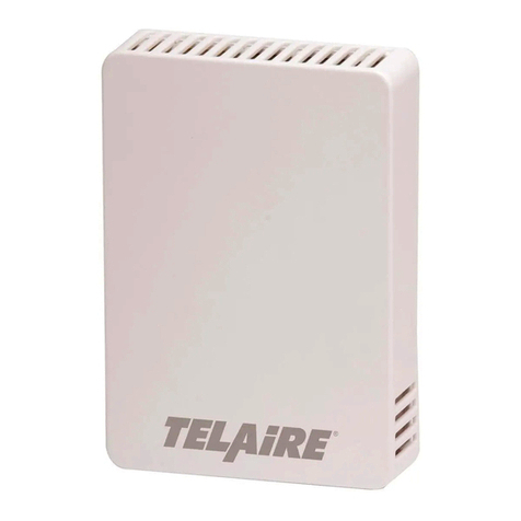
Telaire Ventostat 8000 Series Installation instructions

TRE
IP GAUGE
m/
� 0
N N
u
O
� - J�
> >
2
2-
-
Amphenol
Advanced Sensors
(
rM
�
-------�
I ga-1
Test Equipment Depot - 800.517.8431 - 99 Washington Street Melrose, MA 02176
TestEquipmentDepot.com

Page 2 Telaire Ventostat™ 8000 Series
Ventostat Wiring Diagrams
The Ventostat family of products has two basic configurations. One
configuration provides three active outputs (CO2, RH and temperature)
and an independent thermistor. It has an output terminal block with pins
#1, 2 and 3. The other configuration provides only CO2 outputs and an
independent thermistor and has no terminal block with pins 1, 2, and 3
installed. For electrical wiring and power supply requirements, these two
configurations are identical; please follow the specific instructions for
wiring. The recommended wire gauge is 18-22 AWG (1.0 to 0.75
metric).
!WARNING!
Ventostat products have three terminal pins that are
connected inside the sensor to a common/ground: pin
#2, 5 and 7 on the I/O terminal blocks and pin #2 on the
power block. Do NOT connect positive (hot) 24 VAC power
line to terminal number 2 of the terminal block.
Caution!
The T8100 Ventostats are either 3-wire or 4-wire type
configurations, powered by either AC or DC voltage. They
are not 2-wire or loop-powered devices. Wiring the units as
2-wireorloop-powereddeviceswillirreparablydamage the
sensors and void the warranty.
Note: For temperature measurements, Ventostat models contain a
passive thermistor (terminal pins #4 and 5), which is
electrically isolated from the other circuitry and should be
wired independently from active CO2/RH/temperature outputs.
The thermistor has no connection to the Ventostat common
ground and/or power.
The active temperature output has the same common (ground)
as CO2 and RH outputs.
Figure 1: Display Unit Wiring for 3-Wire System, AC
Power
Figure 2: Display Unit Wiring for 4-Wire System, AC
Power
Figure 3: Non-Display Unit Wiring for 3-Wire System,
AC Power
Figure 4: Non-Display Unit Wiring for 4-Wire System,
AC Power
Figure 5: Wiring CO2Sensor Voltage Output to
Honeywell M7415 Damper Actuator with W7459 Logic
Module
Test Equipment Depot - 800.517.8431 - 99 Washington Street Melrose, MA 02176
TestEquipmentDepot.com


Page 4 Telaire Ventostat™ 8000 Series
Power Consumption
Typical 0.7 W at nominal voltage of 24V AC RMS
Temperature Dependence
0.2% FS per °C (±0.11% per °F)
Stability
T8100/T8300 - Single Channel
<2% of FS over life of sensor (15 years)
T8200 - Dual Channel
<5% of FS or <10% reading annual over life of sensor
(10 years)
Pressure Dependence
0.135% of reading per mm Hg
Certifications
CE and RoHS compliant
Signal Update
Every 5 seconds
CO2 Warm-up Time
< 2 minutes (operational)
10 minutes (maximum accuracy)
Operating Conditions
32°F to 122°F (0°C to 50°C)
0 to 95% RH, non-condensing
Storage Conditions
-40°F to 158°F (-40°C to 70°C)
Flammability Classification
UL94 5VA
Thermistor Type
NTC 10 Kthermistor
Thermistor Accuracy
±1°C (15° to 35°C)
RH Sensing Element
Capacitive polymer sensor
RH Range
0% to 99% RH (non-condensing)
RH Accuracy (25°C)
±2.5% RH (20 to 80% RH)
±3.5% RH (<20% and >80% RH)
Active Temperature Accuracy
±0.8°C @ 22°C
Active Temperature Range
0 to 50°C
ABC Logic™ Self Calibration System
ABC Logic™ (Automatic Background Calibration) self calibration
allows the sensor to continually recalibrate itself when the indoor
concentrations drop to outside levels while the building is unoccupied.
Generally a building must be regularly unoccupied for 4 hours or more
for this self-calibration system to operate properly. Under these
conditions, ABC Logic™ should maintain sensor calibration over the
lifetime of the sensor. The ABC Logic™ should be turned OFF where a
building is continuously occupied 24 hours per day, or where there could
be significant sources of non-occupant related CO2 such as greenhouses,
breweries and other industrial and food processing applications.
Output
Analog
0 to 5 V, (100 output impedance)
0 to 10 V (100 output impedance) and
4 to 20mA (RL maximum 500 ) available simultaneously for CO2
output
Digital to analog error ±1%
Warranty/Other
Warranty
18 months parts and labor
This product is covered by one or more of the following patents:
5,650,624 / 5,721,430 / 5,444,249 / 5,747,808 / 5,834,777 / 5,163,332 /
5,340,986 / 5,502,308 / 6,344,798 / 6,023,069 / 5,370,114 / 5,601,079 /
5,691,704 / 5,767,776 / 5,966,077 / 6,107,925 / 5,798,700 / 5,945,924 /
5,592,147 / 6,255,653 / 6,250,133 / 6,285,290
Warranty Repairs
Amphenol Thermometrics, Inc. will repair Telaire product that fails to
meet the terms provided for in the Return and Warranty Policy
Statement (See, http://www.ge-mcs.com/en/services-and-
support html).Warranty period shall start from date of manufacture and
be based on product category and type of equipment as specified in
Table 1: Product Warranty Periods. For all warranty repairs, Amphenol
Thermometrics, Inc. will bear all product repair parts, labor, and
standard ground shipping charges.
Table of contents
Other Telaire Accessories manuals


