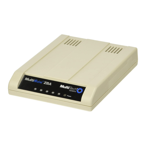
Telebit WorldBlazer User manual

Telebit
Standalone WorldBlazer Modem
User's Guide
90257-01
When
connectivitycounts.

Telebit
Standalone WorldBlazer Modem
User's Guide
90257-01


Preface
The User's Guide is extremely important.
It
contains
information about your modem that the reference manual
does not provide. Be sure
to
keep this guide in a safe
place.
The User's Guide is provided to help you install and
configure your WorldBlazer standalone modem. Read the
User's Guide before you read the reference manual.
If
you
follow the instructions in this guide, you may not need to
consult your reference manual unless you have special
requirements or need more specific instructions.
However, we recommend that you spend some time
reviewing your manual for additional information that is
not covered in this guide.
Copyright © 1992 Telebit Corporation. Telebit
is
a registered trademark
of
Telebit Corporation. Other brands or product names are trademarks or
registered trademarks
of
their respective holders.
90257-01 Preface

ii
Preface 90257-01

Table
of
Contents
Preface
...............................................
i
Introduction .
........................................
1-1
Installation .
.........................................
2-1
Equipment Checklist
..................................
2-1
Installation Checklist
..................................
2-1
Connecting the AC Power Cord
..........................
2-2
Connecting the RS-232 Cable
...........................
2-4
Connecting the Telephone Line
..........................
2-4
Connecting a Telephone
...............................
2-5
After Completing the Installation
.........................
2-5
The Basics.
.........................................
. 3-1
Front Panel Controls and Indicators
......................
3-1
Power Switch
........................................
3-4
Modem Configuration Requirements
...................
'
..
3-4
Prestored Configurations
...............................
3-4
Configuration Memory Organization
.....................
3-8
AT Commands and S Registers
.........................
3-8
Entering a Command
..............................
3-9
Setting a Register
.................................
3-9
Examining an S Register
...........................
3-10
Establishing a Connection
.............................
3-10
Using the Dial Command
..........................
3-10
Using the TID Switch
.............................
3-11
Performing a Reset
...............................
3-11
Using the Auto-Answer Feature
.....................
3-11
Connecting During a Phone Conversation
................
3-11
Ending a Connection
.................................
3-12
Using a Leased Line
..................................
3-12
Telephone Dialer Test
.............................
3-12
Facsimile Capability
..................................
3-13
Standalone Modem Troubleshooting
..................
3-14
90257-01 iii

Standalone Modem Configurations. . . . . . . . . . . . . . . . . . .
..
4-1
Commands
..........................................
4-1
L-Speaker Volume
................................
.4-1
M-Speaker Mode
..................................
4-1
Z-Reset
..........................................
4-2
&D-Data Terminal Ready Interpretation
................
4-2
&F-Load Factory Configuration
......................
4-2
&Q-Asynchronous/Synchronous Mode Select
...........
4-2
&W-Write Current Configuration
....................
.4-2
% Command-Remote Modem Access
..................
4-2
S Registers
..........................................
4-3
S104-Automatic Dialing
............................
4-3
S105-T/D Switch Enable
...........................
.4-3
Prestored Configurations .
............................
A-I
Interface Description. . . . . . . . . . . . . . . . . . . . . . . . . . . . . . .
..
B-1
Leased-Line Considerations .
..........................
C-l
Technical Specifications
..............................
D-l
iv 90257-01

List
of
Figures
Cable Connections
....................................
2-3
Front Panel Display
...................................
3-1
Asynchronous RS-232 Cable Diagram
....................
B-4
Asynchronous Modified RS-232 Cable Diagram
............
B-5
Synchronous RS-232 Cable Diagram
.....................
B-9
Resistor R32
.........................................
C-3
90257-01 v

vi
90257-01

List
of
Tables
Front Panel Status Indicators
.............................
3-2
Prestored Configurations
...............................
3-5
Configurations Set Only With an AT&F Command
...........
3-6
Prestored Configurations
...............................
A-2
RS-232 Connector Pin Assignments
......................
B-2
Internal Resistor (R32) Values
..........................
C-l
Leased-Line Modem Configuration
.......................
C-2
90257-01 vii

viii
90257-01

Introduction 1
90257-01
Telebit's WorldBlazer standalone modem supports full
asynchronous and synchronouscompatibility with dial-up
V.32bis and V.32 modems. The modem features error
control, data compression, facsimile capability, callback
security, remote management, and diagnostics. The
modem operates over both dial-up and 2-wire leased-line
circuits and interoperates with CCITT and Bell standard
modems.
The WorldBlazer standalone modem supports the
enhanced Packetized Ensemble Protocol called
TurboPEP, Telebit'snew multicarriermodulation, as well
as original PEP. The WorldBlazer standalone modem
provides reliable and error-free DTE speeds from 300 to
115,200 bits persecond(bps). The modem is shipped with
prestored configurations that allow operation with a wide
variety
of
industry-standard modems worldwide.
Introduction
1-1

1-2 Introduction 90257-01

Installation 2
This chapter provides instructions for connecting the
WorldBlazer modem between your equipment and the
telephone line. The modem is designed to be used with a
computer, terminal, or other serial device via an RS-232
serial interface port.
Equipment Checklist
Before installing the modem, make sure that you have the
following equipment:
• The AC powercord and transformer provided with
your modem.
• The seven-foot telephone cable supplied with your
modem.
• A shielded RS-232 cable with a DB-25 male
connector for the modem. Your computer dealer
can assist you in obtaining the appropriate cable for
yourrequirements. Pin assignments for the RS-232
connectors are provided in Appendix B, Interface
Description.
If
you do not have these items, obtain them before
proceeding.
Installation Checklist
90257-01
This section summarizes the sequence
of
steps you should
follow to install the modem. For specific instructions on
performing the procedures listed, refer to the specified
page in this manual.
Installation 2-1

1.
Before installing the modem in its final position,
you may need to first connect it to a terminal (or
personal computer with a terminal emulation
program) andpreconfigure it for your system (refer
to Chapter
3,
The Basics).
2.
Verify that the modem's power switch is turned
off, then connect the AC power cord (see below).
3.
Connect a shielded RS-232 cable between the
modem and your equipment (refer to page 2-4).
4.
Connectthe telephone line from the walljackto the
TO LINE connector on the modem (refer to page
2-4).
5.
If
desired, connect your telephone to the TO
PHONE connector on the modem (refer to page
2-5).
6.
Power up the modem and set it up, selecting the
prestored configuration that
best
suits your
application and making any changes
as
needed.
After you have completed the installation, the modem is
ready for use. Refer to Chapter
3,
The Basics, for
information on configuring and using the modem.
Connecting the AC Power Cord
An AC power cord with a transformer assembly is
supplied with the modem.
Warning:
To
avoid damaging the modem,
ONLY
use the
AC
power
cord and transformer provided with your WorldBlazer
modem.
2-2
Installation 90257-01

90257-01
Refer to Figure
2-1
while connecting the AC power cord
to the modem:
1.
Verify thatthe power switch (I/O) on the rear
of
the
modem
is
turned off
(0).
2.
Attach the power cord to the connector labeled
POWER on the rear panel
of
the modem. Ensure
that the bevelededge
of
the plug
is
facing up so that
it mates with the retainer clip on the connector.
3.
Plug the other end of the power cord into a
grounded AC wall outlet.
Figure 2-1. Cable Connections
Installation 2-3

Connecting the RS-232 Cable
A 25-pin female RS-232D connector-, located on the back
of
the unit, is used to connect the modem to your
computer or terminal. You must provide a shielded
RS-232 cable. Pin assignments for the connectors are
listed in Appendix B, Interface Descriptions.
Referto Figure 2-1 while connecting the RS-232 cables to
the modem:
1.
Attach the male connector
of
the RS-232 cable to
the female connector labeled RS-232D on the rear
panel
of
the modem. Tighten the connector screws
until snug.
2.
Attach the other end
of
the RS-232 cable to the
correct RS-232D connector on your DTE. Consult
your equipment manual for the location
of
this
connector.
Connecting the Telephone Line
2-4
A seven-foot telephone cable is provided with your
modem. Use this cable to connect the modem to the
telephone line as shown in Figure 2-1.
Attach one end
of
the provided RJ
-11
telephone cable to
the connector labeled TO LINE on the rear panel
of
the
modem. Attach the other end to your telephone wall jack.
Installation 90257-01

Connecting a Telephone
Your telephone can be connected
to
the modem, allowing
you to make normal telephone calls while your modem
is
not in use. Simply connect the cord from your telephone
to the connector labeled TO PHONE on the rear panel
of
the modem.
After Completing the Installation
90257-01
Before powering on the WorldBlazer modem, refer to
Chapter 3, The Basics, to determine how to configure the
modemto ensure compatibility with yourcomputer's data
communications software.
Installation 2-5

2-6
Installation
90257-01

The Basics 3
This chapter presents a general overview
of
the
WorldBlazer
modem's
operating characteristics and
shows you how to enter commands and set registers that
control the modem's operation.
Proceed
with
this chapter after the modem has been
installed using the instructions in Chapter
2,
Installation.
Front Panel Controls and Indicators
AB
I-
90257-01
The modem's front panel contains two switches and 10
LED indicators, which indicate the current operating
status
of
the modem (refer to Figure 3-1). The status
indicators are described in .Table 3-1.
TID
MR
OH CO PEP EC
OTFI
RTS CTS SO
RO
I-
•
••
• • • • • ••
Figure 3-1. Front Panel Display
The Basics
3-1
Table of contents
Other Telebit Modem manuals
Popular Modem manuals by other brands
Multitech
Multitech MultiModem II MT5600BA-V.92 AT Commands Reference Guide
Multitech
Multitech MultiModem MT5634ZPX-PCI-U-NV user guide
Multitech
Multitech MTSMC-G2 Hardware guide
Multitech
Multitech MultiModem ZPX MT9234ZPX-PCIE-NV-CP user guide
Securakey
Securakey ENTRACOMP 28SA Plus Setup Instructions for Using
NetComm Wireless
NetComm Wireless NL1901ACV Primary Setup Guide
