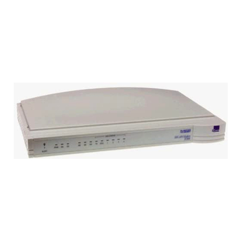
Telebit T2500 User manual


'~

I
~
r
I
Trademarks
Telebit, TrailBlazer, TrailBlazer PC, Packetized Ensemble
Protocol, Adaptive Duplex, and Dynamically Adaptive
Multicarrier Quadrature Amplitude Modulation (DAMQAM)
are trademarks
of
Telebit Corporation.
Hayes is a registered trademark, and V-series and Smartcom III
are trademark
of
Hayes Microcomputer Products, Inc.
Touch-Tone is a registered trademark
of
American Telephone
and Telegraph.
MNP is a trademark
of
Microcom, Inc.
Other Brands
or
product names are trademarks
or
registered
trademarks
of
theirrespective holders.
Firmware
Copyright
Notice
This product contains firmware which has been copyrighted by
Telebit Corporation, Sunnyvale, CA. All rights are reserved.
YOUR RIGHTS OF OWNERSHIP ARE SUBJECT TO THE
LIMITATIONS AND RESTRICTIONS IMPOSED
BY
THE
COPYRIGHT LAWS (TITLE 17, UNITED STATES CODE).
IT IS AGAINST THE LAW TO COPY, REPRODUCE, OR
TRANSMIT (INCLUDING, WITHOUT LIMITATION, ELECTRONIC
TRANSMISSION OVER ANY NETWORK) ANY PART OF THE
FIRMWARE.
THIS IS
NOT
A FULL STATEMENT OF THE COPYRIGHT LAWS.
FOR A COMPLETE STATEMENT OF THE RESTRICTIONS
IMPOSED ON YOU UNDER THE COPYRIGHT LAWS
OF
THE
UNITED STATES, SEE TITLE 17, UNITED STATES CODE.
Rev.D
i

Limitation
of
Warranty
and
Liability
Telebit Corporation has prepared this document for use by
Seller's personnel, customers, and licensees. The information
contained in it is the property
of
Telebit Corporation and shall
not
be
copied, photocopied, translated
or
reproduced in any
electronic
or
machine readable form, eitherin whole
or
in part,
without the written approval
of
Telebit Corporation.
Telebit Corporation
or
Seller shall not
be
responsible for any
loss, cost,
or
damage caused by reliance on these materials.
Telebit Corporation reserves the right to, without notice,
modify
or
revise all
or
part
of
this document and/or change
product features
or
specifications.
Telebit, Seller,
or
any dealer distributing this product, makes
NO WARRANTY, EXPRESSED
or
IMPLIED, with respect to this
manual, and any related items, its quality, performance,
merchantability,
or
fitness for any particular use, Itis solely
the purchaser's responsibility to determine its suitability for
any particular purpose.
Telebit Corporation and Seller will in no event
be
held liable
for direct, indirect,
or
incidental damages resulting from any
defect
or
omission in this manual,
or
any other related items
and processes, including, but not limited to, any interruption
of
services, loss
of
business
or
anticipatory profits,
or
other
consequential damages.
Copyright © 1991 Telebit Corporation.
Printed in U.S.A.
11
Rev.D
L
,~
r
-.
L
..
L.:....
_,
L

r FCC Standards
This equipment generates and uses radio frequency energy,
and
if
not installed and used in strict accordance with the
instructions in this manual, may cause interference to radio and
television reception. It has been tested and found to comply
with the limits for a Class A computing device underPart 15
of
the FCC Rules, which are designed to provide reasonable
protection against such interference in a commercial
installation. However, there is no guarantee that interference
will not occur in a particular installation.
If
this equipment
does cause interference to radio
or
television reception, which
can be determined by turning the modem on and off, the user is
encouraged to try to correct the interference by one
or
more
of
the following measures:
• Reorient the receiving antenna.
• Move the modem away from the receiver,
or
relocate
the receiver with respect to the modem.
• Plug the modem into a different outlet so that the
modem and receiver are on different branch circuits.
If
necessary, you should talk to your dealer
or
any experienced
radio/television technician for additional suggestions. You
may find a booklet prepared by the FCC entitled "How to
Identify
and
Resolve Radio-TVInterference Problems" helpful
in resolving any problems. This booklet is available from the
U.S. Government Printing Office, Washington
DC
20402,
Stock Number 004-000-00345-4.
Rev.
0
111

r -
FCC
Notice
to
Users
1.
2.
3.
4.
iv
'=
Upon request only, you must notify your telephone
utility company (telco)
of
your intentions to install
or
permanently remove an FCC Part 68 registered device,
and provide them with the following information:
•The telephone number to which the equipment will
be connected.
,-
•FCC registration numberER95W5-17716-MO-E.
•Ringer equivalence numbers
O.2A
and
O.3B.
•Modularjacknumber USOC
RJIIC
or
RJ45S.
The equipment may not be used on telco coin-operated
telephone lines. Party lines and privately owned coin-
operated telephone lines are subject to local and state
'--
regulatory policies, andpossible additional state special
features.
The telephone company has the right to make changes
to their network which may affect the operation
of
your r
equipment, provided you are given adequate advance
written notice to permit correct operation.
In the event
of
operational problems, disconnect your L
unit by removing the modular
jack
from the telco's
termination.
If
yourregular phone still works properly, b
your modem may need to be returned for repairs in
or
out
of
warranty.
If
after disconnecting the equipment,
your regular telephone does not operate correctly,
notify your telephone company that they may have a
problem, and request prompt service at no cost to you
the user.
If
a problem is found in premises wiring not
telco-installed, you will be subject to an authorized
service charge.
If
a fault is found in telco-installed
wiring, you may be subject
to
a charge for the service
call.
Rev.D
L
L--
..

5.
6.
Rev. 0
Except as instructed
in
the Diagnostics and Service
chapter
of
this manual, the user may not under any
circumstances (in
or
out
of
warranty) attempt any
service, adjustments
or
repairs on this unit. It must be
returned to the factory
or
authorized service agency for
all such work. Refer to your
Warranty
Registration and
Customer Service Information at the end
of
this manual
for instructions
on
returning your modem for repair.
If
the equipment is to be placed behind a PBX
or
KTS
system,
it
comes under a special FCC category
requiring the written approval
of
the PBX/KTS owner
as well as additional
FCC
registration.
v

'--

rr
I
I
ij
i+
Introduction
I
nsta
Ilation
Using
the
Modem
Conventional
Command
Mode
Configuration Guidelines
Command
Descriptions
Register Descriptions
Enhanced
Command
Mode
Configuration Guidelines
Command
Descriptions
Register Descriptions
Di
nostics
and
Service
Technical
Su
rt
Procedures
Appendices
Glossary
Index
,-
vii


Contents
Cha
pter
1
In
troduction........................................................1·1
Chapter 2 Installation.........................................................2-1
Equipment CheckList................................................2-1
Installation CheckList................................................2-2
Connecting the ACPowerCord..................................2-3
Connecting the RS-232C Cable ..................................2-4
Connecting the TelephoneLine ..................................2-4
Connecting a Telephone .............................................2-5
AfterCompleting the Installation................................2-5
Chapter
3
Using
the
Modem
.......................................3-1
MemoryOrganization ................................................3-1
: DefaultConfigurationSelection .................................3-3
FrontPanel Controls and Indicators ............................3-5
Selecting Conventional
or
Enhanced Command Mode3-8
Enhanced CommandMode........................................3- 8
Conventional CommandMode...................................3-9
PEPSDLCMode
...................................•..................3-10
SDLC Configuration Procedure................................3-10
CommandMode Operation ......................................3-12
ResultCodes.............................................................3-13
Using theDial Command..........................................3-13
Using the AutoAnswerFeature ................................3-14
Changingfrom Voiceto DataConnection ................3-14
Using the CallbackSecurityFeature .........................3-15
Chapter
4 Conventional
Command
Mode
.................4-1
ConfigurationGuidelines ...........................................4-1
Attended
or
UnattendedMode....................................4-2
TransmissionMode Considerations............................4-2
SerialPortInterface SpeedandFlow Control .............4-4
SerialPortInterface Speed....................................4-4
SerialPortFlow Control .......................................4-4
Rev.
0
Contents
1

L
RS-232 Control SignalInterpretations ........................4-5
DCD Signal Handling...........................................4-5
DTRSignal Interpretation ....................................4-5
RTS/CfS SignalHandling ...................................4-6
DSRSignalHandling ...........................................4-6
FileTransferProtocol Support....................................4-6
MNPSupport..............................................................4-7
Command
Descriptions............................................
4-9
i~
ECMAccess Character .....................................4-9 r
A Answer............................................................4-10
B(n) 1200 bps Mode Selection ................................4-10
D(n) Dial .................................................................4-11
E(n) Echo ON/OFF ................................................4-12
F(n) Echoplex ON/OFF..........................................4-12
H(n) Hook ON/OFF ................................................4-13
I(n) Information .....................................................4-13 L
__
L(n) SpeakerVolume ..............................................4-13
M(n) SpeakerON/OFF ............................................4-14
N(n) Transmission SpeedNegotiation ....................4-14
O(n) On-line............................................................4-15
Q(n) QuietEnable ...................................................4-15
S(n)=(x) SetRegister ...............................................4-15
S(n)? Read Register .................................................4-16
V(n) Verbose ON/OFF............................................4-16
W(n) Negotiation ProgressReporting ......................4-17
X(n) ResultCode andDialing Capabilities..............4-17
Y(n) DisconnectonBreak .......................................4-18
Z(n) Reset...............................................................4-19
&C(n) DataCarrierDetectControl ...........................4-19
&D(n) DataTerminal Ready Interpretation ..............4-20
&F RecallFactoryConfiguration Parameters......4-20
&G(n) GuardTone Selection ...................................4-21
&J(n) JackType Selection.......................................4-21
&K(n) Flow Control ................................................4-21 r -
&L(n) LineType Selection .....................................4-22 L
&M(n) CommunicationMode Selection..................4-23
&P(n) PulseDialingMakeIBreak Ratio..................4-24
r-
&Q(n) Communication ModeSelection..................4-24
&R(n) RTS/CfS Signal Interpretation ....................4-25
Contents 2
Rev.
0

&S(n) DataSetReady Interpretation.......................4-26
&T(n) TestFunction ................................................4-26
&
V View Active Configuration andUserProfiles ..4-28
&W(n) Write Configuration Parameters ..................4-28
&X TransmitClockSource ................................4-29
&Y(n) DefaultUserProfile Selection......................4-29
&Z(n)=(x) SetNumberDirectory ............................4-29
RegisterDescriptions..............................................4-31
SO
Answeron Ring Number .................................4-31
S1 Count
of
Rings .................................................4-
31
S 2 Escape Character .............................................4-
31
S3 Carriage Return Character ...............................4-32
S4 LineFeedCharacter.........................................4-32
S5 Backspace Character........................................4-32
S6 WaitTime Before Dialing................................4-33
S7 WaitForCarrierlDialTone Time.....................4-33
S8 PauseTimefor Comma ...................................4-33
S9 CarrierDetectTime .........................................4-33
S10 CarrierLoss to DisconnectTime......................4-34
S
11
TouchToneTiming .........................................4-34
S12 Escape Sequence GuardTime..........................4-34
S
18
TestTermination Timer...................................4-34
S25 DTRDelayTiming ..........................................4-35
S26 RTS to CTS DelayInterval ..............................4-35
S36 Negotiation FailureTreatment .........................4-36
S37 Transmission Mode .........................................4-36
S38 Delay BeforeDisconnecting ............................4-37
Chapter
5
Enhanced
Command
Mode..................•....5-1
ConfigurationGuidelines ...........................................5-1
AttendedorUnattendedMode ....................................5-2
TransmissionMode Considerations............................5-4
V.42 and MNPError Control Protocol Support ..........5-5
DataCompression ......................................................5-7
MNPDataCompression .......................................5-7
V.42bis LAP-MDataCompression ......................5-8
PEPDataCompression ...............................................5-8
SerialPortInterface Speed andFlow Control .............5-8
SerialPortInterface Speed....................................5-9
SerialPortFlow Control .....................................5-11
Rev.D Contents 3

RS-232 Control Signal Interpretations ......................5-12
DTRSignal Interpretations ................................5-13
DSRSignalHandling .........................................5-13
DCD SignalHandling ........................................5-14
crsSignal Handling .........................................5-14 I
L"
BreakSignalandEscape SequenceHandling ...........5-15
FileTransferProtocols Support ................................5-16
,-
SDLC Support ..........................................................5-17
Transparent Synchronous Support ...........................5-17
BitSynchronousDialing in SDLC Support...............5-18
CommandDescriptions ..........................................
5·19
A Answer ............................................................5-19
C(n) Tum CarrierON/OFF.......................................5-20
D(n) Dial...................................................................5-20
E(n) Echo ON/OFF ..................................................5-22
F(n) Echoplex ON/OFF............................................5-22 L
_-"
G GoToVoice ..................................................5-23
H(n) Hook ON/OFF ..............................................5-23
I(n) Infonnation ...................................................5-23
M(n) SpeakerON/OFF...........................................5-25
N(n)=(x) Set NumberDirectory ...............................5-25
N(n)? Display Number ............................................5-26
N? Display NumberDirectory andS Registers...5-26
o On-line ..........................................................5-26
Q(n) QuietEnable..................................................5-27
S(n)=(x) SetRegister ...............................................5-28
S(n)? Read Register................................................5-28
U Update SystemPassword ..............................5-28
V(n) Verbose ON/OFF .........................................5-29
W(n) Negotiation Progress Reporting....................5-29
X(n) Result Code BasiclExtended ........................5-30
Y(n) Disconnecton Break.....................................5-30
Z(n) Reset ............................................................5-31 L ,
&B
Blind Command...........................................5-31
&E(n) Recall EEPROM OperatingParameters .......5-32
&F(n) Recall Factory Configuration Parameters ....5-32 L _
&N(n) DisplayEEPROM OperatingParameters ....5-33
&P(n) PulseDialingMakelBreak Ratio..................5-33 L
&R(n) Force Retrain
or
Renegotiate........................5-33
Contents 4
Rev.
0

&T(n) TestFunction ...............................................5-34
&W(n) Write Configuration Parameters ..................5-36
% Remote Modem Access ..............................5-37
Register
Descri
ptions..............................................5-39
SO
Answeron Ring Number ............................5-39
SI CountofRings ............................................5-39
S2 Escape Character ........................................5-40
S3
Carriage Return Character ..........................5-40
S4 Line Feed Character....................................5-40
S5
Backspace Character...................................5-40
S6 Dial Tone WaitTime ..................................
5-41
S7
WaitForCarrierTime.................................
5-41
S8
Pause Time for Comma...............................
5-41
S9
CarrierDetectTime ....................................
5-41
S
10
CarrierLoss
to
DisconnectTime .................
5-41
S
11
Touch Tone Timing ....................................5-42
S
12
Escape Sequence GuardTime ....................5-42
S
18
Test Termination Timer..............................5-42
S25
DTRDelayTiming ....................................5-42
S26
RTS
to
CTS
Delay Interval ........................5-43
S
38
Delay Before Disconnecting ......................5-43
S41 Inactivity Timer .........................................5-44
S45
Remote Access Enable...............................5-44
S46
Callback Security.......................................5-45
S47
DSRlDCD Delay Time ..............................5-46
S48
EightBit Comparison ................................5-46
S49
Product Identification String Redefinition .5-47
S50 Transmission Mode ...................................5-48
S51
Interface Speed .........................................5-50
S52 DTR Interpretation....................................5-52
S54
Break Signal Interpretation .......................5-53
S55 Escape Character/Sequence Interpretation 5-54
S56 XON Character .........................................5-54
S57 XOFF Character........................................5-55
S58
Flow Control Used byDTE.......................5-55
S59
Prompt Character ......................................5-57
S61
SpeakerVolume........................................5-57
S62 BreakLength Time ...................................5-57
S63 Command Mode Selection........................5-57
S64 Dial/Answer Sequence Abort....................5-59
I~
Rev.D
Contents
5

S65
S66
S67
S68
S69
S70
S71
S72
S73
S74
S75
S76
S77
S78
S90
S91
S92
S93
S94
S95
S96
S97
S98
S100
S101
S102
S104
S105
S106
S107
S108
S110
S111
S112
S121
S130
S131
S150
S151
Contents
6
XON/XOFF
Failsafe
.................................5-59
Lock
Interface
Speed
................................5-60
crs
Signal
Interpretation
.........................5-61
Flow
Control
Used
by
DCE
......................5-62
XON
Signal
Handling
...............................5-63
Instantaneous
Transmit
Rate
...
..................5-63
Transmit
Bits
Per
Channel
........................5-64
Instantaneous
Receive
Rate
......................5-64
Receive
Bits
Per
Channel
..........................5-64
Received
Packets
Retransmitted
...............5-65
Packets
Accepted
......................................5-65
Equivalent
Line
Noise
Profile
...................5-65
Frequency
Offset
......................................5-65
Line
Quality
...
...........................................5-66
CCITTlBell
Mode
Select.............................5-66
Guard
Tone
Selection...................................5-67
Answering
Sequence
Selection ....................
5-67
V.32
AC
Transmit
Duration
.........................
5-68
Transmission
SpeedNegotiation..................5-68
MNP
Operating
Mode
..................................5-69
MNP
Data
Compression
Enable
...................5-70
V.42LAP-MEnable ....................................5-71
V.42bis
Data
Compression
...........................
5-71
Answer
in
Originate
Mode
...........................5-72
Continuous
Answer/Originate
.....................5-72
Auxiliary
Telco
Lead
Setting
.......................5-73
Automatic
Dialing
Options
..........................5-73
TID SwitchEnable.......................................5-75
V.42 Detection
Enable
.................................5-75
Detection
Timer
...........................................5-77
V.42
Match
Count
.......................................
5-77
PEP
Data
Compression
Enable
....................5-78
File
Transfer
Protocol
Support
.....................5-78
Kermit
Mark
Character
................................5-80
Echo
Suppressor
Compensation
..................
5-81
Data
Set
Ready
Interpretation
......................
5-81
Data
Carrier
Detected
Interpretation
............5-82
Async/Sync
Mode
Selection ........................5-83
SDLC
Interface
Speed
.................................5-84
Rev.
0
l.
L
L.
L
,
--
,~
:-
--,
I'
L
,.
I··
I'

F-
I
I"
S152
S153
S154
S155
S157
S158
S160
S161
S162
S163
S164
S169
S222
S255
SDLCSwitchedlNonswitched .....................5-86
SDLCFulVHalfDuplexMode Selection .....5-86
Synchronous ClockOptions ........................5-87
NRZ/NRZIDataEncoding ..........................5-87
SDLCDisconnectionDelayTime ...............5-88
SDLC
DSR
Delay Time...............................5-88
SDLCFrame RetransmitLimit....................5-89
SDLCDeviceTimeout ................................5-89
SDLC NonproductiveTimeout....................5-90
SDLC RetransmitTimeout ..........................5-90
SDLCPrimary Poll Rate ..............................5-90
SynchronousDialing Command
Set
Enable 5-91
ECM
Access Character................................5-92
DefaultUserProfile Selection......................5-93
Chapter
6 Diagnostics
and
Service
...........................6-1
Diagnostic Tests .........................................................6-1
UserAssuranceTests..................................................6-2
Nonvolatile MemoryTest...........................................6-2
TelephoneDialerTest.................................................6-2
TelephoneLineRelay Test .........................................6-3
RingDetectTest .........................................................6-3
Troubleshooting .........................................................6-4
Chapter
7
Technical
Support
Procedures
.................7-1
Return for RepairProcedure .......................................7-2
TwoYearLimitedWarranty.......................................7-3
TwoYearLimitedWarranty Extension ......................7-5
Appendices
Appendix A ASCII Code Chart.................................
A-l
Appendix B InterfaceDescription .............................B-1
Appendix C CommandCross Reference ...................
C-l
AppendixD ResultCodes .........................................
D-l
AppendixE T2500 to T2500 Interconnection............
E-l
AppendixF LeasedLine Considerations ...................
F-l
AppendixG Technical Specifications........................
G-l
Rev. D
Contents
7

1",,-
List
of
Figures
2-1
T2500 Cable Connections...........................................
2-3
L
3-1
T2500Memory Organization .....................................3-2
3-2 DefaultSetDisplay .....................................................3-4
B-1
Asynchronous RS-232C Cable Diagram....................
B-5
,
I..:..
_"
B-2 Special Asynchronous RS-232C CableDiagram .......B-6
B-3 SDLC & Transparent Synchronous RS-232C Cable ........
Diagram .....................................................................B-9
F-1
Gain ControlResistorLocastion.................................F-2
List
of
Tables
3-1
FrontPanel Control Switches .....................................3-5
3-2 FrontPanel Status Indicators ......................................3-7
3-
3 SDLC Configuration Cross Reference ......................
3-11
5-1
AttendedMode Configuration ....................................5-2
l.=.
.J
5-
2 Unattended Mode Configuration ................................
5-
3
5-3 V.42 Error Control......................................................5-6
5-4 V.42 Error Control ....................................................5-76
5-5 Transparent Synchronous Cross Reference...............5-85
6-1
Modem Preconfiguration ............................................
6-5
6-2 Placinga Call..............................................................6-6
6-3
Answering aCall ........................................................6-9
6-4 Call In Progress.........................................................6-12
B-1
PhoneLine ConnectorPinDefinition.........................
B-1
B-2 RS-232 ConnectorPin Assignments ..........................B-2
D-1
Conventional Command Mode Result Codes ............D-2
D-2 ErrorControl Call Progress Result Codes ..................D-3
D-3
Enhanced CommandMode Result Codes ..................D-4
D-4 MNP Extended Result Codes .....................................D-5
D-5 PEPExtended Result Codes ......................................
D-5
Glossary ............................................................Glossary 1
Index .....................................................................
Index
1
L
Contents
8 Rev.D
L.

I~
Chapter 1
Introduction
This manual provides acomprehensive guide
for
setting
up
and
using theTelebitT2500 modem. The manual is intendedfor
computer and terminal users who have a basic understanding
of
datacommunications.
You can save time by following the instructions in the T2500
FastStartGuide, which is a separate booklet provided
to
help
you get started using your modem
as
quickly
as
possible.
If
you
have special requirements orexperience
any
problems while
using the T2500 FastStartGuide, referto this manual for
additional information.
The T2500 modem overcomes the limitation ofdial-up tele-
phone lines by using Packetized EnsembleProtocol™ (PEP)
modulation. PEP analyzes the quality ofthe connection at
511
separate frequency points and compensates for line impairments
which may exist. The modem's advanceddesign is ideally
suited for high speedfile transferoperations. Accordingly, you
will gain the most benefits
in
line costs and time savings when
transferring large files.
Some
of
the major features offered
by
the T2500 modem are
discussed in the following sections:
V.42
Error
Control
Protocol
Support
The T2500modem supports
V.42
errorcorrection and detection
protocol standard that provides error-free transmission overa
standardfull-duplex, V.32, V.22bis, V.22, and Bell 212A
connection.
Rev. 0 Page
1-1
Table of contents
Other Telebit Modem manuals
