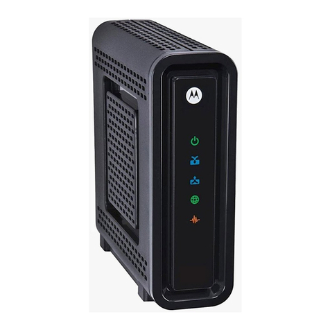
Telebit NetBlazer STi User manual

Part Number 90453-02
Revision A0
Copyright © 1997 Telebit, Inc.
Printed in U.S.A.
STi and 40i Installation Guide
NetBlazer®
NetBlazer STi
¤
LAN POWER RESET
NetBlazer 40i
LAN POWER RESET
¤
Book Page 1 Thursday, March 27, 1997 10:55 AM

Book Page 2 Thursday, March 27, 1997 10:55 AM

90453-02 Rev A0 iii
TELEBIT, INC. SOFTWARE LICENSE AGREEMENT
License.
This software (the "Software") and related documentation are licensed to you by
Telebit, Inc. (“Telebit”). Both the Software and the documentation are protected under
applicable copyright laws, international treaty provisions and trade secret statutes of
various states. This License Agreement grants you a non-exclusive and non-transferable
license to use the Software for your internal purposes solely in conjunction with the
replacements, accessories, spare parts and upgrades listed on Telebit's current product price
list ("Equipment"). This is not an agreement for the sale of the Software or the
documentation or any copy of the Software or the documentation and you have not
acquired title or ownership in the Software or the documentation or any copies or part
thereof. Your right to use the software and the documentation is subject to the following
further terms and conditions: i) Any Software, including any subsequent updates as
provided herein, is licensed solely in object code form for internal use only in connection
with the associated Equipment purchased by you pursuant to this Agreement. You shall
pay Telebit's prevailing license fee (less any applicable discount) for each copy of any
Software package licensed by you; ii) You may obtain updates to such Software which
Telebit makes generally available for licensing on the associated Equipment, provided you
obtain a license for each such updates from Telebit at Telebit's then prevailing fee; iii) You
shall not provide, disclose or otherwise make available the Software in any form to any
person other than your employees without Telebit's prior written consent, except when any
such person is on your premises and under your direction and control for purposes
specifically related to your permitted use of the Software.
You may make one (1) copy of any Software licensed from Telebit solely for back up or
archival purposes, provided you reproduce and include Telebit's copyright and other
proprietary rights notices on and in any such copy. Any copy which you make of the
Software, in whole or in part, is the property of Telebit.
Restrictions.
Telebit reserves all rights not expressly granted to you by this License
Agreement. The Software contains copyrighted materials, trade secrets, and other
proprietary information and in order to protect them you may not copy, reproduce, modify,
reverse assemble, reverse compile or otherwise reverse engineer or create derivative works
of the Software in whole or in part. For information regarding interoperability, write:
Telebit, Inc., One Executive Drive, Chelmsford, MA 01824, Attn: Technical Support
Department. You agree to take appropriate action by instruction, agreement or otherwise
with your employees or other persons allowed access to the Software to satisfy its
obligationsunderthisAgreementwithrespecttotheuse,copying,modification,disclosure,
protection and security of the Software. You must have a reasonable mechanism or process
to ensure that the number of users at any one time does not exceed the number of licenses
you have paid for and to prevent access to the Software to any person not authorized under
the above license to use the Software. Your license to use the Software and documentation
willautomaticallyterminateifyoufailtocomplywith the terms of thisLicenseAgreement.
If this license is terminated you agree to destroy all copies of the Software and
documentation in your possession.
Book Page iii Thursday, March 27, 1997 10:55 AM

iv 90453-02 Rev A0
TELEBIT, INC. LIMITED WARRANTY
Limited Warranty on Media.
Telebit warrants to the original licensee that the media on
which the Software is recorded will be free from defects in materials and workmanship
under normal use for a period of ninety (90) days from the date of delivery. Telebit's entire
liability and your exclusive remedy pursuant to this limited warranty shall be limited to
replacement of the defective media. If failure of the media has resulted from accident,
abuse or misapplication of the product, Telebit shall have no responsibility to replace the
media under this limited warranty.
Disclaimer of Warranty on Software.
The Software and related documentation are
provided "AS IS" and without warranty of any kind. TO THE EXTENT PERMITTED BY
LAW, TELEBIT EXPRESSLY DISCLAIMS ALL WARRANTIES, EXPRESS OR
IMPLIED, INCLUDING BUT NOT LIMITED TO THE IMPLIED WARRANTIES OF
MERCHANTABILITY AND FITNESS FOR A PARTICULAR PURPOSE. TELEBIT
DOES NOT WARRANT THAT THE FUNCTIONS CONTAINED IN THE SOFTWARE
WILL MEET YOUR REQUIREMENTS, OR THAT THE OPERATION OF THE
SOFTWARE WILL BE UNINTERRUPTED OR ERROR-FREE, OR THAT DEFECTS
IN THE SOFTWARE WILL BE CORRECTED. FURTHERMORE, TELEBIT DOES
NOT WARRANT OR MAKE ANY REPRESENTATIONS REGARDING THE USE OR
THE RESULTS OF THE USE OF THE SOFTWARE OR RELATED
DOCUMENTATION IN TERMS OF THEIR CORRECTNESS, ACCURACY,
RELIABILITY, OR OTHERWISE. NO ORAL OR WRITTEN INFORMATION OR
ADVICE GIVEN BY TELEBIT OR A TELEBIT AUTHORIZED REPRESENTATIVE
SHALL CREATE A WARRANTY OR IN ANY WAY INCREASE THE SCOPE OF
THIS WARRANTY.
TELEBIT SHALL IN NO EVENT BE LIABLE FOR ANY SPECIAL, COLLATERAL,
INCIDENTAL OR CONSEQUENTIAL DAMAGES INCLUDING WITHOUT
LIMITATION ANY CLAIM FOR LOST OR DAMAGED DATA, NETWORK DOWN
TIMEORDEGRADEDPERFORMANCE, LOSTPROFITSORLOSSOF GOODWILL.
In no event shall Telebit's total liability to you for all damages, losses and causes of action
whether in contract, tort (including negligence) or otherwise exceed the amount paid by
you for the Software.
U.S. GOVERNMENT RESTRICTED RIGHTS
The Software and documentation are provided with RESTRICTED RIGHTS. Use,
duplication, or disclosure of the Software by the U.S. Government is subject to restrictions
as set forth in subdivision (c) (1) of the Rights in Technical Data and Computer Software
clause at 252.227-7013. Use, duplication, or disclosure of the Technical Data by the U.S.
Government is subject to restrictions as set forth in subdivision (b) (3) of the Rights in
Technical Data and Computer Software clause at 252.227-7013. Use, duplication, and
disclosure by the governments of any other countries is subject to restrictions to similar
applicable laws.
The parties hereto agree that the United Nations Convention on the International Sale of
Goods shall not apply to this License agreement.
Book Page iv Thursday, March 27, 1997 10:55 AM

90453-02 Rev A0 v
General.
This License shall be governed by and construed in accordance with the laws of
the Commonwealth of Massachusetts, excluding its conflict of law rules, and shall inure to
the benefit of Telebit, its successors, representatives and assigns. The license granted
hereunder may not be assigned, sublicensed or otherwise transferred by you. If any
provisions of this Agreement shall be held to be invalid, illegal or unenforceable, the
validity, legality and enforceability of the remaining provisions shall in no way be affected
or impaired thereby.
For more information about Telebit’s licensing policies, write: Telebit, Inc., One
Executive Drive, Chelmsford, MA 01824, Attn: Contract Administrator.
Trademarks
Telebit, NetBlazer, WorldBlazer, TrailBlazer, QBlazer, and QBlazer Plus are registered
trademarks of Telebit, Inc.. FastBlazer and Xpresso are trademarks of Telebit, Inc..
Telebit gratefully acknowledges the following additional copyrights:
– Apple and AppleTalk are trademarks of Apple Computer, Inc.
Other brands or product names are trademarks or registered trademarks of their respective
holders.
THIS IS NOT A FULL STATEMENT OF THE COPYRIGHT LAWS. FOR A
COMPLETE STATEMENT OF THE RESTRICTIONS IMPOSED ON YOU UNDER
THE COPYRIGHT LAWS OF THE UNITED STATES, SEE TITLE 17, UNITED
STATES CODE.
Limitations
The information contained in this document is believed to have been accurate at the time
of printing. However, Telebit, Inc. assumes no liability for errors or omissions.
In keeping with a philosophy of continual product improvement, Telebit reserves the right
to make changes in its documentation and/or product specifications at any time without
notice.
Limitation of Warranty and Liability
Telebit, Inc. has prepared this document solely for use by Seller’s personnel, customers,
and licensees. The information contained in it is the property of Telebit, Inc. and shall not
be copied, photocopied, translated, or reproduced in any electronic or machine readable
form, either in whole or in part, without the written
approval of Telebit, Inc..
Book Page v Thursday, March 27, 1997 10:55 AM

vi 90453-02 Rev A0
Telebit, Inc. or Seller shall not be responsible for any loss, cost, or damage
caused by reliance on these materials. Telebit, Inc. reserves the right, without notice, to
modify or revise all or part of this document and/or change product features or
specifications.
Telebit, Seller, or any dealer distributing this product, makes NO WARRANTY,
EXPRESS or IMPLIED, with respect to this manual, and any related items, its quality,
performance, merchantability, or fitness for any particular use. It is solely the purchaser’s
responsibility to determine its suitability for any particular purpose.
Telebit, Inc. and Seller will in no event be held liable for direct, indirect, or incidental
damages resulting from any defect or omission in this manual, or any other related items
and processes, including, but not limited to, any interruption of services, loss of business
or anticipatory profits, or other consequential damages.
Power Cord
The NetBlazer can be used only with a power cord that meets the rating of the unit, that is,
1.5A/250V. THE POWER CORD MUST BE APPROVED ACCORDING TO THE
STANDARDS OF THE COUNTRY IN WHICH THE UNIT IS USED. Telebit is not
responsible for damages or losses caused by the use of the unit with an underrated,
nonstandard, and unapproved power cord.
FCC Warning
This equipment has been tested and found to comply with the limits for a Class A digital
device pursuant to Part 15 of the FCC Rules. These limits are designed to provide
reasonable protection against harmful interference when this equipment is operated in a
commercial environment. This equipment generates and uses, and can radiate radio
frequency energy and, if not installed and used in accordance with Telebit, Inc. manuals,
may cause harmful interference to radio communications. Operation of this equipment in a
residential area is likely to cause harmful interference in which case the user will be
required to correct the interference at his/her own expense.
Operation of this equipment is subject to the following conditions:
1.
This equipment may not cause harmful interference, and
2.
This equipment must accept any interference received, including in-
terference that may cause undesired operation.
SHIELDED CABLES: This product has been tested and found to comply with the FCC
limits for a Class A computing device. The testing was done with the use of shielded cables.
The use of any cable other than the shielded type will certainly mean your system will emit
excess amounts of radio frequency interference thereby increasing the likelihood of
interference. Therefore, in order to comply with the FCC Regulations, it is necessary that
you use good quality cables.
Book Page vi Thursday, March 27, 1997 10:55 AM

90453-02 Rev A0 vii
Canadian Notices
ThisClass A digital apparatus meets all requirementsof the Canadian Interference-Causing
Equipment Regulations.
Cet appareil numérique de la classe A a respecte toutes les exigences du Règlement sur le
matériel brouilleur du Canada.
CE Marking Statement
In certain countries, this equipment meets the Low Voltage and EMC Directives of the
European Union. The CE marking is applied to this equipment with regards to those
directives.
EN 55022 Warning
This is a Class A product. In a domestic environment, this product may cause radio
interference in which case the user may be required to take adequate measures.
Warning
The total of all adapter boards installed in this NetBlazer product must not exceed the
power specifications stated in this manual. All additional boards having a direct connection
to the public network must have the mandatory approvals.
With the NetBlazer STi and 40i, indirect connections to the Wide Area Network (WAN)
are established with synchronous, asynchronous, or ISDN plug-in boards. These devices
must comply with the requirements of the country in which they are used. The interface
parts must meet minimum clearance and creepage distances with respect to other internal
parts in order to meet the international and local safety requirements.
Likewise, external devices attached via the plug-in board’s synchronous or asynchronous
ports must comply with the requirements of the country in which they are used.
Caution:
Changes or modifications to this equipment not expressly approved by the
party responsible for compliance could void the user’s authority to operate
the equipment.
Book Page vii Thursday, March 27, 1997 10:55 AM

viii 90453-02 Rev A0
To maintain the independent approval of the X.21 board, it is essential that, when other
option boards are introduced that use or generate a hazardous voltage, the minimum
creepages and clearances specified in the table below are maintained. A hazardous voltage
is one that exceeds 42.4V peak a.c. or 60V d.c. If you are in doubt, seek the advice of a
competent engineer.
Clearance (mm) Creepage (mm) Voltage Used or Generated by
Host or Other Boards
2.0 2.4 (3.8) Up to 50 V
rms
or V
dc
2.6 3.0 (4.8) Up to 125 V
rms
or V
dc
4.0 5.0 (8.0) Up to 250 V
rms
or V
dc
4.0 6.4 (10.0) Up to 300 V
rms
or V
dc
For a host or other expansion board fitted in the
host, using or generating voltages
greater than
300V (rms or dc), advice from a competent tele-
communications safety engineer must be obtained
before installation of the relevant equipment.
Above 300 V
rms
or V
dc
Book Page viii Thursday, March 27, 1997 10:55 AM

90453-02 Rev A0 ix
How to Use This Manual
This manual is a guide to installing NetBlazer STi and NetBlazer 40i
hardware. It is intended to be used by network administrators and/or service
personnel responsible for hardware installation.
This manual consists of the following chapters and appendices:
•
Chapter 1, Introduction, provides an overview of the NetBlazer. It
also provides some basic product specifications and steps for plan-
ning your installation.
•
Chapter 2, NetBlazer Installation, provides instructions for install-
ing your NetBlazer.
•
Appendix A, Specifications, provides specification information for
the STi and 40i.
•
Appendix B, Cable Applications, provides wiring diagrams for
those who wish to fabricate their own cables.
•
Appendix C, Telebit Cables, provides wiring diagrams for cables
and adapters supplied by Telebit.
•
Appendix D, NetBlazer Combo Board, provides information on its
4 different functions.
Book Page ix Thursday, March 27, 1997 10:55 AM

x 90453-02 Rev A0
Related Documentation
Telebit recommends that you configure your NetBlazer using the NetBlazer
Setup Utility. For instructions, see the
NetBlazer Setup Utility Guide
that
was shipped with your NetBlazer.
The
NetBlazer Configuration Guide
describes how to use NetBlazer
commands to customize a broad range of operational parameters.
Complete descriptions and examples of all NetBlazer commands are in the
NetBlazer Command Reference Manual
, that was shipped with your
NetBlazer, or when you are logged in to the NetBlazer as
root
, you can type
man introduction
or
man netblazer
for information on man pages and
NetBlazer commands.
Book Page x Thursday, March 27, 1997 10:55 AM

90453-02 Rev A0 Table of Contents xi
Table of Contents
Caution: How to Use This Manual ..........................................................................ix
Related Documentation........................................................................................................x
Table of Contents....................................................................................................xi
1 Introduction...................................................................................................... 1-1
NetBlazer STi Description............................................................................................... 1-1
NetBlazer 40i Description................................................................................................1-3
Hardware Configuration ..................................................................................................1-5
Modem Compatibility...................................................................................................... 1-7
Preinstallation Planning...................................................................................................1-9
Choosing a Location..................................................................................................1-9
General Planning........................................................................................................1-9
2 NetBlazer Installation ...................................................................................... 3-1
AC Power Cord Connection ............................................................................................3-1
Installing a NetBlazer STi Option Board.........................................................................3-1
Closing the NetBlazer STi Case ...................................................................................... 3-2
Installing a NetBlazer 40i Option Board ......................................................................... 3-2
Closing the NetBlazer 40i Case....................................................................................... 3-4
Optional Rackmount Kit..................................................................................................3-4
Applying Power to the NetBlazer....................................................................................3-4
Turning Off the NetBlazer’s Power.................................................................................3-4
Using the Reset Button ....................................................................................................3-5
Types of LAN Connections.............................................................................................3-5
Types of WAN Connections............................................................................................ 3-5
A Specifications...................................................................................................A-1
......................................................................................................................................... A-2
B Cable Applications...........................................................................................B-1
Standard Asynchronous RS-232 Cables....................................................................B-2
Null-Modem Asynchronous RS-232 Cables .............................................................B-3
Dual BRI ISDN Board Cable.....................................................................................B-4
NS1 Single-Port Synchronous Board Cables.............................................................B-4
Book Page xi Thursday, March 27, 1997 10:55 AM

xii Table of Contents 90453-02 Rev A0
C Telebit Cables.................................................................................................. C-1
RS-232 Cables ...........................................................................................................C-2
Null-Modem Adapter.................................................................................................C-3
Gender Adapter..........................................................................................................C-4
RS-449 Cable for the SYN449 Board........................................................................C-5
RS-232 Cable for the SYN232 Board........................................................................C-6
V.35 Cable for the SYN35 Board..............................................................................C-7
RS-530 Cable for the SYN530 Board........................................................................C-8
X.21 Cable for the SYNX21 Board...........................................................................C-9
NS1 Single-Port Synchronous Board Cable............................................................C-10
D NetBlazer Combo Board................................................................................. D-1
Book Page xii Thursday, March 27, 1997 10:55 AM

90453-02 Rev A0 Introduction 1-1
Introduction 1
The first two sections of this chapter provide an overview of the NetBlazer
STi and NetBlazer 40i products and briefly describe the applications for
which these products are suited. A list of the option boards for the NetBlazer
STi and NetBlazer 40i are provided. If you need to preconfigure or change
existing configuration settings in an option board, you will be directed to re-
fer to the appropriate option board document.
The Preinstallation Planning section on page 1-9 suggests what you can do
before you install your NetBlazer.
The NetBlazer STi and NetBlazer 40i support the most popular LAN and
WAN environments, with up to three Ethernet and/or Token Ring LAN
connections, asynchronous connections up to 64 ports, synchronous con-
nections up to 10 ports, or up to 24 ISDN B channels. Both models provide
WAN access over ISDN, frame relay, Switched 56, leased lines up to T1/E1
speeds, and support high-speed analog dial-up modems. The NetBlazer STi
and 40i also have 12 megabytes of system memory.
NetBlazer STi Description
The NetBlazer STi, shown in Figure 1-1, is a rack-mountable or desktop
device suited for installation in regional sites as a dial-up router linking one
or two Ethernet or Token Ring LANs to an enterprise-wide network. Its
ability to use synchronous ports makes it a cost-effective leased-line router,
a leased-line backup device, or a router for switched digital services such as
Integrated Services Digital Network (ISDN) and Switched 56. When used
with a NetBlazer MTA32 Rack Adapter, the NetBlazer STi can also act as
aremote-accesscommunicationsserverfortelecommutingapplicationsthat
require up to 32 serial ports for modems.
Book Page 1 Thursday, March 27, 1997 10:55 AM

1-2 Introduction 90453-02 Rev A0
Figure 1-1. The NetBlazer STi
Figure 1-2 shows the NetBlazer STi front panel with a 1.44-Mbyte, 3.5-inch
floppy diskette drive, two status indicators, and a reset switch, all located on
the right side. The LED labeled LAN shows Ethernet network activity. The
LED labeled POWER shows that power is on. The POWER indicator blinks
on and off while the system is powering up.
Figure 1-2. NetBlazer STi Front View
NetBlazer STi
¤
LAN POWER RESET
NetBlazer STi
¤
LAN POWER RESET
Book Page 2 Thursday, March 27, 1997 10:55 AM

90453-02 Rev A0 Introduction 1-3
Figure 1-3 shows a typical NetBlazer STi rear panel. The chassis I/O ports,
line00 and line01, are RS-232 9-pin ports available for connection to a
modem or asynchronous terminal at speeds up to 115.2 Kbps. The console
port is also an RS-232 serial port for use with an asynchronous terminal op-
erating at 9600 baud. The NetBlazer STi includes 12 megabytes of system
memory.
Figure 1-3. NetBlazer STi — Typical Rear Panel
NetBlazer 40i Description
The NetBlazer 40i, shown in Figure 1-4, is the most powerful member of
the NetBlazer line of modular routers. The NetBlazer 40i is designed as a
large multiport solution where a high-speed processor and performance is
critical. It is designed for mounting in a 19-inch rack, or can be used on a
desktop or shelf. Applications for which the NetBlazer 40i is suited include
central sites that need up to 32 serial modem ports (NetBlazer 40i with a
NetBlazer MTA32 Rack Adapter).
NetBlazer
®
line00 line01
NetBlazer Combo Board
Status
line02
(console)
LEDs
Book Page 3 Thursday, March 27, 1997 10:55 AM

1-4 Introduction 90453-02 Rev A0
Figure 1-4. The NetBlazer 40i
Figure 1-5 shows the NetBlazer 40i front panel with a 1.44-Mbyte, 3.5-inch
floppy diskette drive, two status indicators, and a reset switch, all located on
the right side. The LED labeled LAN shows Ethernet network activity. The
LED labeled POWER shows that power is on.
The POWER indicator blinks
on and off while the system is powering up.
Figure 1-5. NetBlazer 40i Front View
NetBlazer 40i
LAN POWER RESET
¤
NetBlazer 40i
LAN POWER RESET
¤
Book Page 4 Thursday, March 27, 1997 10:55 AM

90453-02 Rev A0 Introduction 1-5
Figure 1-6 shows a typical NetBlazer 40i rear panel. The power switch is
located near the fan above the power connector.
Figure 1-6. NetBlazer 40i — Typical Rear Panel
The console port is an RS-232 serial port for use with an asynchronous
terminal operating at 9600 baud (do not use the console port as a modem
port). To the right of the console port are the chassis I/O ports. The Net-
Blazer 40i includes12 megabytes of system memory.
Hardware Configuration
You can install up to three option boards in the NetBlazer STi, and up to six
option boards in the NetBlazer 40i.
Table 1-1 provides a list of available options. Contact your distributor or
reseller for up-to-date ordering information on NetBlazer options.
NetBlazer
®
NetBlazer Combo Board
line00
line01
line02
(console)
Book Page 5 Thursday, March 27, 1997 10:55 AM

1-6 Introduction 90453-02 Rev A0
Table 1-1. NetBlazer Options
Model Product Description
MICA Granite Module Twenty three or 30 ISDN or analog modem connec-
tions through the MVIP bus.
NE1 Ethernet Board Ethernet port with AUI, BNC and RJ-45 connectors.
Cable is not provided.
NTR Token Ring Board Token Ring port with UTP and STP connectors.
Cable is not provided.
NM8 Async Multiport Board Multiport controller with 8-port expansion cable.
ASYN8
ASYN8+
Async Multiport Board and one
8-port multiple terminal adapter
(MTA)
Add-on 8-port MTA unit
The NetBlazer STi/40i supports up to four ASYN8
controller boards with up to eight MTAs evenly dis-
tributed among the ASYN8 controller boards for a
total of 64 RS-232 ports. RS-232 cables are not
included.
No more than four MTAs may be connected to a
single ASYN8 controller board.
NI2B Dual-Port ISDN BRI Board Two ISDN basic-rate interface (BRI) S/T interfaces.
Each provides two 64-Kbps B-channels and a 16-
Kbps D-channel. 4-to-1 compression is available
with negotiation. Cable is not provided.
NI1P ISDN PRI Board One ISDN interface that provides 23 (TI) or 30 (E1)
B-channels. 8-pin modular connector for connecting
to DSU/CSU. Cable is not provided.
NICC Compression Coprocessor
Board Uses the VLB/PCI bus to automatically perform
compression/decompression functions.
NS1 Single-Port Sync Board 56/64 Kbps synchronous port with V.35 interface
and cable. The board can be reconfigured for an
RS-232 or RS-449 connection. RS-232 or RS-449
cables are not provided.
SYN232 RS-232 Dual-Port Sync Board Two RS-232 synchronous ports rated at T1/E1
speeds. Both ports have an RS-232 interface.
Includes RS-232 cables.
SYN35 V.35 Dual-Port Sync Board Two V.35 synchronous ports, rated at T1/E1 speed
and the other at 128 Kbps. Includes V.35 cables.
Book Page 6 Thursday, March 27, 1997 10:55 AM

90453-02 Rev A0 Introduction 1-7
Modem Compatibility
The NetBlazer currently supports the Telebit modems and firmware levels
listed in Table 1-2. If you have a Telebit modem that is not at the required
firmware level, contact Telebit Customer Support at 508.656.9453 for infor-
mation about obtaining a firmware upgrade.
If you are using modems not made by Telebit, you may need to modify the
MODEMCAP.TXT
file. See the NetBlazer Configuration Guide for more
information.
SYN449 RS-449 Dual-Port Sync Board Two RS-449 synchronous ports, rated at T1/E1
speeds . Includes RS-449 cables.
SYN530 RS-530 Dual-Port Sync Board Two RS-530 synchronous ports, rated at T1/E1
speeds. Includes RS530 cables.
SYNX21 X.21 Dual-Port Sync Board Two X.21 synchronous ports, rated at T1/E1
speeds. Includes X.21 cables.
Table 1-1. NetBlazer Options (Continued)
Model Product Description
Book Page 7 Thursday, March 27, 1997 10:55 AM

1-8 Introduction 90453-02 Rev A0
Table 1-2. Supported Telebit Modems
Modem Firmware Level Firmware Level for
AppleTalk ARA Service
Granite Module 1.00 or later 2.00 or later
FastBlazer 88x0 Series 1.00 or later 2.00 or later
TeleBlazer V1.100b-V34_DS Z201 or later NA
WorldBlazer SA or RM LA5.00 or later LA7.05C or later
T3000 SA or RM LA5.00 or later LA7.05C or later
QBlazer Plus QF2.00 NA
Xpresso 8x96 series 3.43 or later NA
T1600 SA LA5.00 or later LA7.05C or later
QBlazer MA1.01 NA
T2500 SA or RM GE6.01, GE7.00, GF7.00, or later NA
T1500 SA GE6.01, GF7.00, or later NA
TrailBlazer Plus SA or RM BC7.00, GF7.00, or later NA
T2000 SA or RM BC7.00 NA
T1000 SA or RM Fx2.00 or later NA
x = any letter or number SA = standalone RM = rackmount
Book Page 8 Thursday, March 27, 1997 10:55 AM
This manual suits for next models
1
Table of contents
Other Telebit Modem manuals
