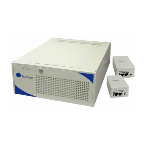
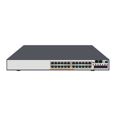
Telebyte 458-SM-2-16 User manual

Model 458-SM-2-16
Transparent Switching Module
Rev. B
7/30/2011
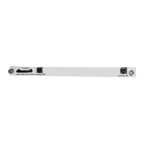
The 458-SM-2-16 shown installed in the 458-3SLB (not included).
“Results You Can Count On”

Customer Support
Contact Information:
Telephone E-mail/Internet
Fax: 1-631-385-8184 www.telebytebroadband.com
Mail
Telebyte, Inc.
355 Marcus Blvd
Hauppauge, NY 11788 USA

Warranty
Included With Your Purchase
One-year Warranty
• Telebyte will furnish parts and labor for the repair or replacement of products found by Telebyte to
be defective in material or workmanship during the warranty period.1
Extended Customer Care
Our three-year extended warranty extends the original warranty by an additional 36 months.
Three-Year Extended Warranty
You can extend the original one-year warranty that comes with your product by purchasing the
Three-Year Extended Warranty.2
Features:
·Telebyte will furnish parts and labor for the repair or replacement of products found by Telebyte to be defective
in material or workmanship during the warranty period.1
Disclaimer of Warranties and Other Terms and Conditions
1TELEBYTE, INC. warrants its broadband simulation equipment to be free from defects in material and workmanship, under normal and proper
use and in its unmodified condition, for 12-months, starting on the date it is delivered for use. TELEBYTE’S sole obligation under this warranty
shall be to furnish parts and labor for the repair or replacement of products found by TELEBYTE to be defective in material or workmanship during
the warranty period. Warranty repairs will be performed at the point of manufacture. Equipment approved for return for warranty service shall be
returned F.O.B. TELEBYTE factory and will be redelivered by TELEBYTE freight prepaid, except for non-continental U.S.A. locations. These
deliveries will be sent COD freight and import/export charges.
2 You must purchase the extended warranty at the time of purchase or during the initial warranty period.
The above warranty is in lieu of all other warranties, expressed or implied, statutory or otherwise, including any implied warranty of merchantability
or fitness for a particular purpose. TELEBYTE shall not be liable for any damages sustained by reseller or any other party arising from or relating
to any equipment failure, including but not limited to consequential damages, nor shall TELEBYTE have any liability for delays in replacement or
repair of equipment.

Equipment Returns
Out of warranty equipment may be returned, prepaid, to the Hauppauge, N.Y.
customer service facility. Return shipping charges will be billed to the
customer. The repaired unit will have a 90-day warranty. In those cases
where "no trouble" is found, a reduced charge will be billed to cover handling,
testing, and packaging. Whether in or out of warranty, a Return Material
Authorization number (RMA) is required and may be obtained by going to
www.telebytebroadband.com and opening a technical support case.
Please be sure to reference the RMA number on the outside container.

Table of Contents
1.0 Specifications ........................................................................................ 1
2.0 Description............................................................................................. 2
2.1 General Description............................................................................... 2
2.2 Operation as a Multiplexer .................................................................... 4
2.3 Operation as a Demultiplexer................................................................ 5
3.0 Mechanical Specifications..................................................................... 6
4.0 Connector Interface............................................................................... 7
4.1 Pin Numbering RJ-45............................................................................ 7
5.0 Environmental Specifications................................................................ 8
6.0 Control................................................................................................... 9
6.1 Transparent Switching Module Commands .......................................... 9
6.1.1 Command Codes And Responses........................................................ 9
6.1.1.1 Codes .................................................................................................... 9
6.1.1.2 Responses............................................................................................. 9
6.1.2 Command Sequence........................................................................... 10
6.2 Transparent Switching Module Truth Tables ...................................... 11
6.3 Example Commands........................................................................... 12
6.4 Manual/Keypad Controls..................................................................... 13
6.4.1 LCD/Keypad (458-3SLB)..................................................................... 13
6.4.2 LCD/Keypad (458-CC-16/458-CM)..................................................... 13
6.5 458 Universal Graphical User Interface .............................................. 14

Model 458-SM-2-16 Transparent Switching Module Page 1 of 14
1.0 Specifications
Product Specifications
Signal Switching Capability Multiplexing:
16 balanced input lines to 1 of 2 balanced output lines (16x1); or
16 balanced input lines to both balanced output lines (8x2)
Demultiplexing:
1 balanced input line to 16 balanced output lines (1x16); or
2 balanced input lines to 8 balanced output lines each (2x8)
Insertion Loss Less than 0.5 dB from DC to 30 MHz
Less than 1 dB up to 60 MHz
Noise Floor Less than -140 dBm/Hz from DC to 30MHz
Tip and Ring Balance Better than 53 dB up to 12 MHz
Degrading by 20 dB per decade from 12 MHz to 30 MHz
Return Loss 26 dB minimum up to 30 MHz (100-ohm reference)
Crosstalk Between Lines Maximum -90 dB up to a minimum frequency of 30 MHz
Temperature Operating: 0°C to 50°C (32°F to 122°F)
Storage -20°C to 70 °C (-18°F to 158°F)
Operating Relative Humidity 0% to 95% relative humidity (non-condensing)
Dimensions Overall: 12.21”H x 0.86”W x 20.85”D
(310mm H x 22mm W x 529mm D)
Connectors 16 RJ-45’s on front, 2 RJ-45’s on back
Relay Cycles of Operation 5,000,000 cycles
Toxic Materials Complies with RoHS Directive
Specifications are subject to change without notice. Made in USA.

Model 458-SM-2-16 Transparent Switching Module Page 2 of 14
2.0 Description
2.1 General Description
The Model 458-SM-2-16 Transparent Switching Module (referred to as the Switching Module throughout this document)
is a transparent, electronically neutral multiplexing device that allows up to sixteen incoming lines to share (be directed
to) one or two independent output channels.
The Switching Module is bi-directional and does not contain active electronic components in the signal path between
input and output connectors. Therefore, it may be used in the reverse direction as a demultiplexer to direct one channel to
one of sixteen independent lines, or two independent channels to one of eight independent lines.
A high-level block diagram of the Model 458-SM-2-16 as a Multiplexer connected to a Telebyte Line Simulator (Local
Loop Simulator) is shown in Figure 1. The Matrix Block switching is accomplished by double coil state-stable ‘latch’
relays that are powered and switched by logic commands generated by the firmware interface to select or change the input
to output paths. The Telebyte Line Simulators use the same state-stable relays to allow the selection of line lengths for
each of its various Channels. Therefore, the loss of power to the Switching Modules and Line Simulators do not change
settings allowing the Switching Modules and Line Simulators to continue functioning during power loss and at power
recovery at its last setting.
The 458-3SLA (3-Slot) Chassis shown on the front cover would utilize one Switching Module with each Line Simulator,
which allows the various input signals to be selected by the Module and provided to the input Channels of the Line
Simulator. However, the Switching Module may be used alone or in any mixed combination, and located in any desired
slot of the chassis enclosure.
Figure 1 shows a high-level block diagram of the Model 458-SM-2-16

Model 458-SM-2-16 Transparent Switching Module Page 3 of 14
Figure 1: High Level Block Diagram of Model 458-SM-2-16

Model 458-SM-2-16 Transparent Switching Module Page 4 of 14
2.2 Operation as a Multiplexer
The front of the Switching Module contains sixteen RJ-45 connectors in two groups of eight RJ-45’s. Therefore, each
Switching Module can accept and multiplex up to sixteen independent incoming differential lines to one or two outgoing
differential lines.
The rear of the Switching Module has two R-J45 Output Connectors where each connector can be assigned to one
differential Input Signal. Therefore, two of the sixteen Input Signals can be multiplexed to the two Output Connectors,
and the two Switching Module outputs can be directly connected to two independent channel inputs of the Telebyte
family of Local Loop Simulators, or other similar devices.
The Switching Module operates in three possible modes:
In the first mode, the Output Channel 1 RJ-45 rear connector can select any of the16 incoming lines (Input
Signals) from the 16 RJ-45 front connectors. Selection of incoming lines 9 through 16 is allowed only when
the Output Channel 2 rear RJ-45 connector path is disabled.
In the second mode, the Output Channel 2 RJ-45 rear connector can select any of the16 incoming lines (Input
Signals) from the 16 RJ-45 front connectors. Selection of incoming lines 1 through 8 is allowed only when
the Output Channel 1 rear RJ-45 connector path is disabled.
In the third mode, the block of 16 incoming lines (Input Signals) are partitioned into two groups of 8 signal
inputs. The Output Channel 1 RJ-45 rear connector can select any of the incoming lines 1 through 8, and the
Output Channel 2 rear RJ-45 connector can simultaneously select any of the incoming lines 9 through 16.
Switching between modes is permitted only when the specified Output Channel is selected. This prevents a channel from
being discontinued when not specified in a command. Therefore, when switching modes it may be necessary to disable
the other channel (see Truth Table).
The selection and control of the paths from input to output is through firmware installed on the Telebyte 458-CM that is
associated with the 458-CC-16 (16-Slot) chassis, or on the 458-3SL/3SLA (3-Slot) chassis. The commands are provided
in the Appendix. The basic command consists of three numbers:
The physical slot location of the Module in the chassis to be changed. The location of slot 1 is at the left side
of the 458-CC-16 (16-Slot) chassis and is the top slot of the 458-3SL/3SLA (3-Slot) chassis.
The Output Channel (output connector 1 or 2) that the signal is to go to. The location of Channel 1 is the
upper connector at the rear of the Switching Module.
The Input Signal (1 through 16) that is to be selected to go to the selected Output Channel, including no
signal. Input Signal 1 is the upper RJ-45 connector of the upper RJ-45 block, and Input Signal 16 is the
bottom RJ-45 connector of the lower RJ-45 block on the front of the Switching Module.
The same Input Signal of each of the sixteen inputs is prevented from being routed to more than one Output Connector by
two different control systems, which prevents impedance division.
The Matrix Block relay logic is configured as an ‘exclusive or’ (XOR) so that only one input can be switched
to only one output.
The firmware logic that controls the selection prevents the selection of more than one input of the group for
each output, and prevents the input from use at any other output.

Model 458-SM-2-16 Transparent Switching Module Page 5 of 14
To minimize input signal reflections and source noise, all unselected input signal lines are terminated with a 100-ohm
0.25 watt resistor, and all unselected channel output lines are source terminated with a 100-ohm 0.25 watt resistor.
2.3 Operation as a Demultiplexer
Model 458-SM-2-16 Transparent Switching Module may also be used as a demultiplexer. The paths between the input
and output connectors are bi-directional, which allow signals to flow in either direction without a change in the signal
characteristics. Therefore, two input signals may be connected to the RJ-45 rear connectors, and provide the selection of
up to sixteen outputs at the front 16 RJ-45 connector lines. The selection of the paths and the firmware control logic in the
demultiplexer configuration is identical to the control logic and selection when used as a multiplexer. The paths are:
Mode 1: The upper RJ-45 rear connector input signal may connect to any one of the front 16 RJ-45
differential lines when the lower-rear RJ-45 is not selected.
Mode 2: The lower RJ-45 rear connector input signal may connect to any one of the front 16 RJ-45
differential lines when the upper-rear RJ-45 is not selected.
Mode 3: The upper RJ-45 rear connector input signal may connect to any one of the front RJ-45 connectors 1
though 8 differential lines and the lower RJ-45 rear connector input signal may connect to any one of the front
RJ-45 connectors 9 through 16 differential lines.

Model 458-SM-2-16 Transparent Switching Module Page 6 of 14
3.0 Mechanical Specifications
The Model 458-SM-2-16 mechanical design is based on the mechanical dimensions of the Telebyte Line Simulator
product line. These units fit into the Telebyte 458-CC-16 (16-Slot) chassis and 458-3SLA (3-Slot) chassis which can be
mounted in a 19-inch rack.
The overall dimensions of the 458-SM-2-16 are provided in the Specifications section and include the front and rear
panels and handle dimensions.
The Switching Module contains sixteen RJ-45 connectors on the front panel that provide sixteen connection paths, and
two RJ-45 connectors on the rear panel that provide two connection paths.
When used in a Telebyte Model 458-CC-16 with 458-CM or a 458-3SLA chassis, a front panel LCD is available for
monitoring the selection or status of each Switching Module path.

Model 458-SM-2-16 Transparent Switching Module Page 7 of 14
4.0 Connector Interface
4.1 Pin Numbering RJ-45
The pin numbering and location of connections to the RJ-45 connector is shown in Figure 2. The front sixteen
input connectors are grouped in two blocks of eight RJ-45 connectors each.
Figure 2: RJ-45 Connector Pin Location

Model 458-SM-2-16 Transparent Switching Module Page 8 of 14
5.0 Environmental Specifications
All components used for the Transparent Switching Module exceed the specified temperature range of operation and
storage. The continuous power consumption of the components on each Module is less than 0.05 watts and intermittent
short peaks of 2.5 watts when banks of relays are being switched. These power levels are insignificant and do not
contribute to temperature rise of the module or its location of use.

Model 458-SM-2-16 Transparent Switching Module Page 9 of 14
6.0 Control
6.1 Transparent Switching Module Commands
The Transparent Switching Module Commands are applicable to RS232 and IEEE modes.
6.1.1 Command Codes And Responses
6.1.1.1 Codes
M= Module Number
A two digit number, with leading 0, that selects the physical location/slot of the Module in the chassis
(01, 02…16 for a 458-CC-16 chassis and 01, 02, 03 for a 458-3SLA chassis)
H= Channel Number
A one-digit number that selects one of the two rear (RJ-45) output channel connectors (referred to as Output
Channel 1 or Output Channel 2).
I= Input Signal Number
A one- or two-digit number that selects one of the sixteen front (RJ-45) connectors (and 0) associated with signal
inputs to its Matrix Block, for connection to the selected Output Channel. The examples refer to these as Input
Signal 1-16.
A= Reset
Resets ALL Input Signals and Output Channels of the selected Module to no signal input and no channel output,
and terminates each input and output in 100 ohms.
SC = Set Connection
Sets the selected Module Slot location to the selected Output Channel and the selected Input Signal.
RC = Read Connection
Reads the selected Input Signal at the selected Module and Channel.
6.1.1.2 Responses
*Indicates that a command is valid and completed execution.
? [###] ______ Indicates an invalid condition.
? [###] Card Not Found Indicates that a Module is not at the specified location.
? [###] Invalid Card Number Indicates that the Module number is outside of the system range.
? [###] Invalid Channel Number Indicates that the Output Channel number is outside of the Module range.
? [###] Invalid Command Indicates any error not covered by the above responses.
The bracketed numbers are internal control numbers.
Display responses are as above but abbreviated.\

Model 458-SM-2-16 Transparent Switching Module Page 10 of 14
6.1.2 Command Sequence
Set Connection Command
SC:M:H:I
Sets Module location/slot Mand Output Channel number Hto Input Signal number I, or to 0 (terminated).
The response is * when the Command is accepted and execution is completed, or an Invalid Command statement.
Read Connection Command
RC:M:H
Requests the Input Signal setting from Module location/slot M, Output Channel number H.
The response is M:H:I where M is the Module location/slot, H is the Output Channel number, and I is the Input
Signal number, or an Invalid Command statement.
Channel Reset Command
SC:M:H:0
Sets Module location/slot Mand Output Channel number Hto 0 (no Line Number). Output Channel H
differential line is terminated with a 100-ohm resistor.
The response is * when execution is completed, or an Invalid Command statement.
Module Reset Command
SC:M:A:0
Sets Module location/slot M, ALL Output Channels to 0 (no Line Number). Each differential Input Signal and
Output Channel source of the Module is terminated with a 100-ohm resistor.
The response is * when execution is completed, or an Invalid Command statement.
Valid Module Commands (see Truth Table)
Output Channel 1 may be assigned to any Input Signal number 1-16 when Output Channel 2 is not assigned to an
Input Signal.
Output Channel 1 may be assigned to any Input Signal number 1-8 when Output Channel 2 is assigned to any
Input Signal number 9-16.
Output Channel 2 may be assigned to any Input Signal number 1-16 when Output Channel 1 is not assigned to an
Input Signal.
Output Channel 2 may be assigned to any Input Signal number 9-16 when Output Channel 1 is assigned to any
Input Signal number 1-8.

Model 458-SM-2-16 Transparent Switching Module Page 11 of 14
6.2 Transparent Switching Module Truth Tables
Table 1 - Input Line Group Selection vs. Output Channel 1-2 for Input Signals 1-16 in Mode 3
0 = not selected input line; no active output signal is available.
1 = selected input line; an active output signal is available.
T = Invalid Selection or indeterminate.
Channel 1 allows line 1-16 to be selected and is limited to lines 1-8 when Channel 2 is active in lines 9-16.
Channel 2 allows line 1-16 to be selected and is limited to lines 9-16 when Channel 1 is active in lines 1-8.
Line Input Selects Active Outputs
Channel 2 Select Channel 1 Select Channel 1 Channel 2
Line 9-16 Line 1-8 Line 9-16 Line 1-8
0 0 0 0 0 0
0 0 0 1 1 0
0 0 1 0 1 0
0 0 1 1 T 0
0 1 0 0 0 1
0 1 0 1 T* T**
0 1 1 0 T* T**
0 1 1 1 T T**
1 0 0 0 0 1
1 0 0 1 1 1
1 0 1 0 T* T**
1 0 1 1 T T**
1 1 0 0 0 T
1 1 0 1 T* T
1 1 1 0 T* T
1 1 1 1 T T
* If Channel 1 is selected first it disables Channel 2 from using the same Line group.
** If Channel 2 is selected first it disables Channel 1 from using the same Line group.

Model 458-SM-2-16 Transparent Switching Module Page 12 of 14
6.3 Example Commands
The below examples are for Input Signals 1-16 and Output Channels 1-2, for the Module in location/slot 5 of the
enclosure. Each example is dependent on the prior example selection state. A table is displayed that shows the same
examples in a different format.
EXAMPLE STATEMENT CODE/RESPONSE
Example 1
Read the Input Signal number that is at Output Channel 2, of the Module in slot 5 RC:05:2
Response is: Input Signal is (0) reset/inactive and terminated. 05:2:0
Example 2
Set Input Signal 3 to Output Channel 1, at the Module in slot 5. SC:05:1:3
Response is: command completed. *
Note: Valid as Output Channel 2 of Ex 1 is inactive.
Example 3
Set Input Signal 6 to Output Channel 2, at the Module in slot 5. SC:05:2:6
Response is: invalid. ? [###] Invalid Connection
Note: Input Signal 6 cannot be selected by Output Channel 2 as the Module is in Mode 1.
Example 4
Set Input Signal 10 to Output Channel 2, at the Module in slot 5. SC:05:2:10
Response is: command completed. *
Note: Output Channel 1 connection is unchanged. The Module is in Mode 3
with both Output Channel 1 and 2 active.
Example 5
Set Module in slot 5, Output Channel 1, to 0. SC:05:1:0
Response is: command completed. *
Note: Output Channel 2 is unchanged. Output Channel 1 is terminated
in 100 ohms and Input Signal 3 is terminated in 100 ohms.
Example 6
Terminate all Input Signals/all Output Channels of the Module SC:05:A:0
in slot 5.
Response is: command completed. *
Note: All 16 Input Signals and 2 Output Channels of the Module are set to
a 100-ohm termination.
Examples Shown Above, in Table Format
Command Slot
(1-3 or 1-16)
(2 Digits)
Output Channel
(1-2 or A for ALL)
(1 Digit)
Input Signal
(1-16 or 0)
(1 or 2 Digits)
RC 05 2
SC 05 1 3
SC 05 2 6
SC 05 2 10
SC 05 1 0
SC 05 A 0

Model 458-SM-2-16 Transparent Switching Module Page 13 of 14
6.4 Manual/Keypad Controls
6.4.1 LCD/Keypad (458-3SLB)
The example above shows a setting of “slot 01, rear channel 1, input signal 12”
6.4.2 LCD/Keypad (458-CC-16/458-CM)
The example above shows a setting of “slot 01, rear channel 1, input signal 12”

Model 458-SM-2-16 Transparent Switching Module Page 14 of 14
Keypad Controls (458-SM-2-16)
1. Up Arrow: increase slot/channel number
2. Down Arrow: decrease slot/channel number
3. Left Arrow: decrease input signal number
4. Right Arrow: increase input signal number
5. C: Config switch used to access second menu for communications settings such as RS232
baud rates, GPIB addresses, etc.
Baud Rates: 19200, 9600, 4800, 2400, 1200, 600
GPIB Addresses: 1 – 30
Please note the information in this section pertains to the 458-SM-2-16 only. If using a loop simulator in the same
chassis, the values shown for the slot containing the loop simulator will relate to selections appropriate for
product installed. For example, the right and left arrows will increase and decrease line lengths for slot 2 if a loop
simulator is installed in slot 2.
6.5 458 Universal Graphical User Interface
Refer to the 458 Universal Graphical User Interface Reference Manual for more information.
Table of contents
Other Telebyte Switch manuals
