Teleco TVNRG868E04 User guide

Product:
TVNRG868E04
Doc:
T928.01_EN
Date:
02/09/2021
Control system for garage doors
Installer’s instruction manual

2
PRODUCT DESCRIPTION
1
TVNRG868E04
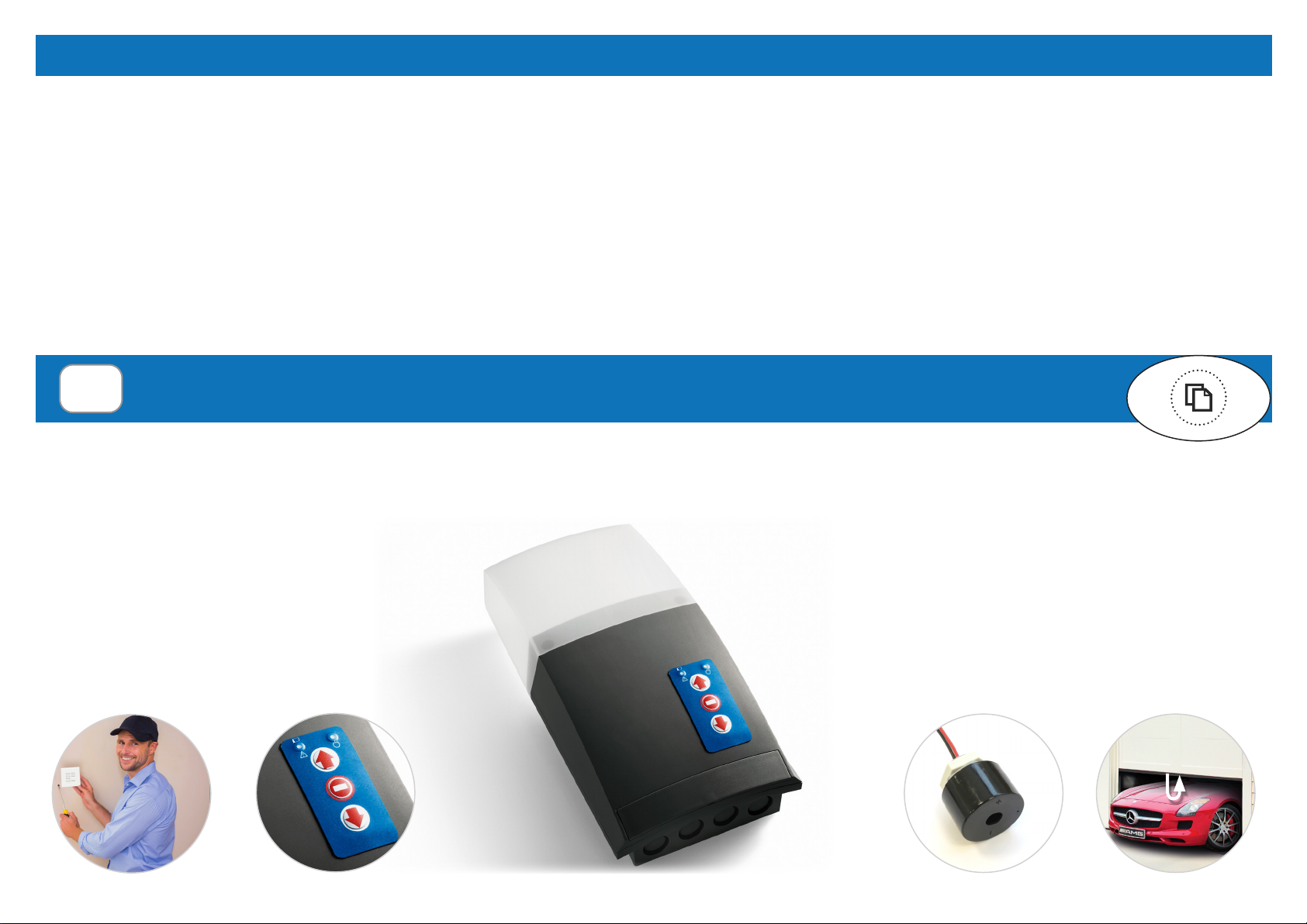
Control unit with integrated radio receiver for the remote control of tubular motors up to 450W, with built-in limit switch, for rolling shutters and rolling doors.
FEATURES
- Compact plastic case with easy fixing
- Front cover with buttons for up/stop/down commands and
LED for alarms status
- Integrated LED courtesy light
- Wireless control via radio transmitters
- Wireless safety edge with auto-test
- Bidirectional communication: door status is shown by the
transmitter LED with different colour
- Alarm function, in combination with shock sensor (TVSSH868A01 and
BST25S) and integrated speaker
W
i
r
e
l
e
s
s
s
y
s
t
e
m
e
a
s
y
t
o
c
o
n
n
e
c
t
W
i
r
e
l
e
s
s
s
a
f
e
t
y
s
y
s
t
e
m
F
r
o
n
t
c
o
v
e
r
w
i
t
h
u
p
/
s
t
o
p
/
d
o
w
n
b
u
t
t
o
n
s
O
p
t
i
o
n
a
l
a
l
a
r
m
b
u
z
z
e
r
t
o
b
e
fi
t
t
e
d
i
n
t
h
e
c
a
s
e
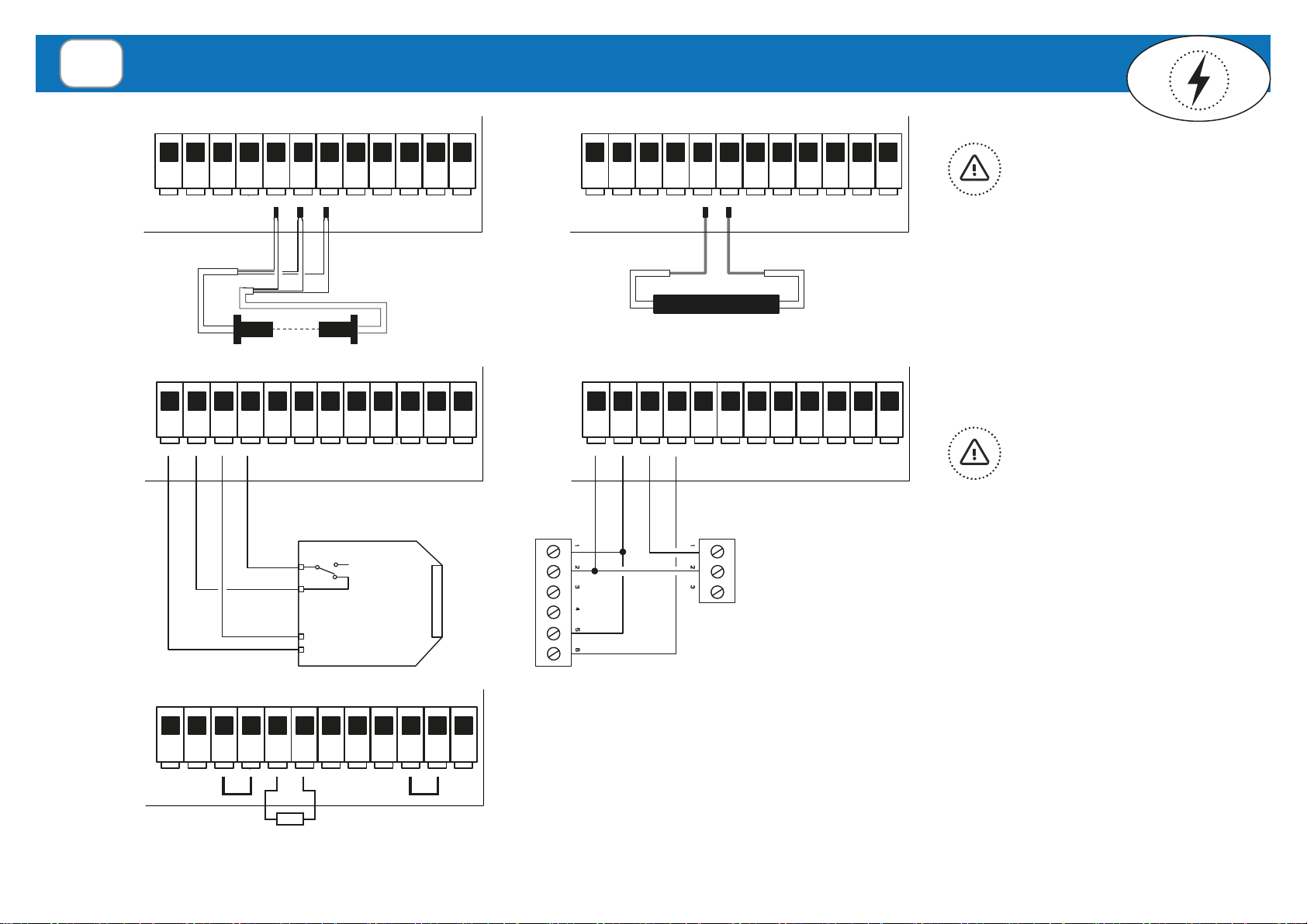
CONNECTIONS & FUNCTIONING
- Wired inputs for safety edge (both resistive 8K2 and infrared)
- Wired inputs for command push-button and emergency STOP push-button
- Possibility to connect an external 240Vac courtesy light
- 2 Functioning modes: semi-automatic (automatic opening + hold-to-run
closing) and automatic
- Automatic closing with programmable pause time
- Exclusion of the safety edge in the last part of the closure, in case of bumpy
floor
- Motor torque control
- “Holiday mode” to lock the control unit with the front cover
INDEX
1. Product description ----------------------------------------------------------------page 2
2. Installation -----------------------------------------------------pages 3 - 8
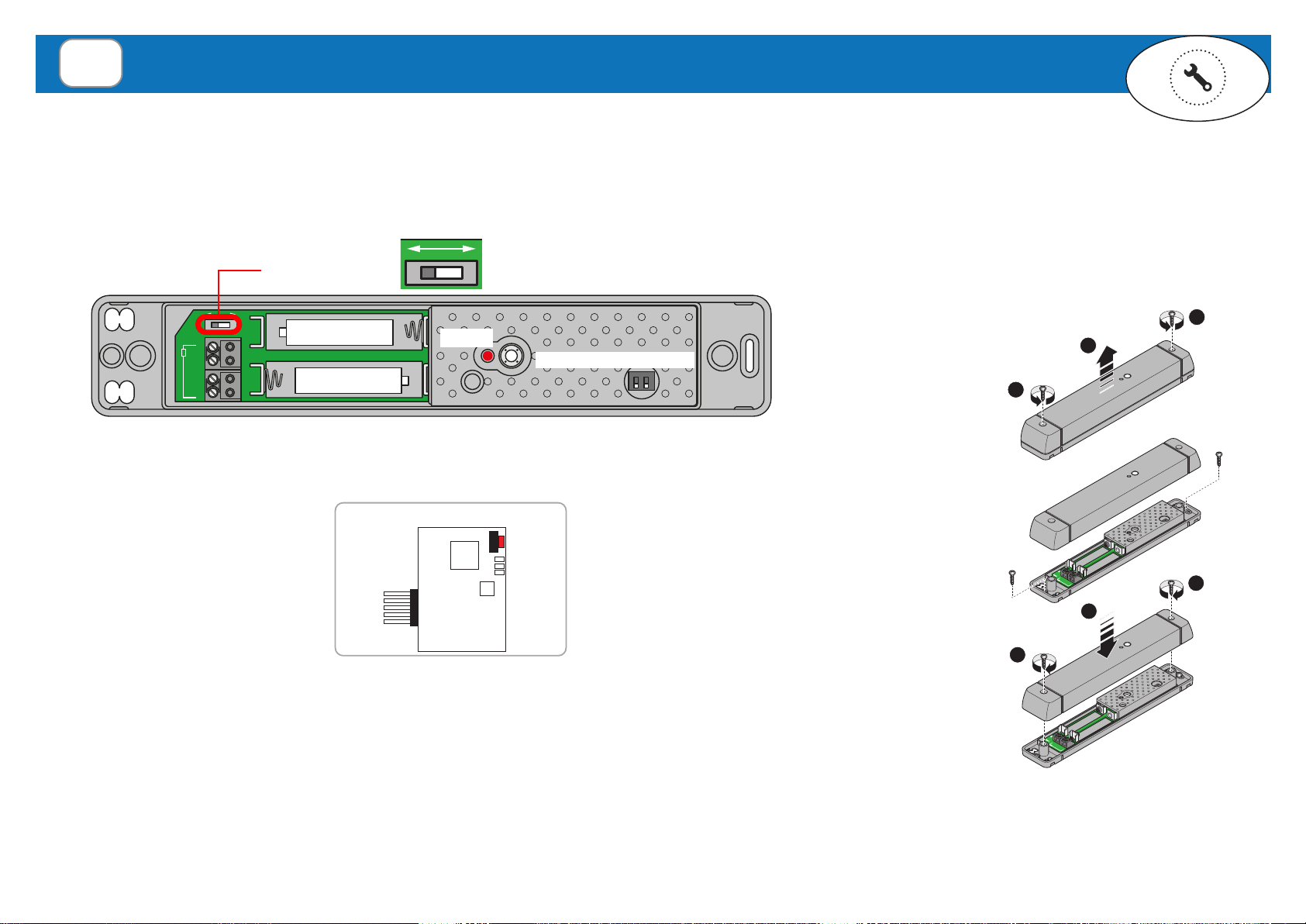
2.1 Mounting the product
2.2 Control Unit diagram
2.3 Electrical connections
2.4 Wired safety device connections
2.5 Mounting the wireless “shock” safety system (BST26)
3. Preliminary check and initial start-up ---------------------------------------------pages 9 - 10
3.1 Limit switch configuration and direction check
3.2 Matching of the wireless safety device system & Activation/Deactivation
3.3 Functioning mode
3.4 Exclusion of safety edge
4. Transmitters & memorization -----------------------------------------------------pages 12 - 15
4.1 Radio codes memorization
4.2 Single channel: door status request (ask)
4.3 Alarm function: shock sensor memorization
4.4 Remote memorization of the first transmitter
4.5 Remote memorization of further transmitters
5. Transmitters deletion --------------------------------------page 16
5.1 Remote deletion of a transmitter
6. Time setting ----------------------------------------------------------------page 17
6.1 Auto close time setting
6.2 Courtesy light time setting
7. Other programming --------------------------------------------------------page 18
7.1 Motor torque control
7.2 “Holiday mode”
8. Troubleshooting --------------------------------------------------------page 19
Technical specification

3
INSTALLATION
2
Basic installation
1 - NRG control unit
2 - Tubular motor (240Vac)
3 - Hand transmitter
4 - Safety edge wireless transmitter
Complete installation
1 - NRG control unit
2 - Tubular motor (240Vac)
3 - Hand transmitter
4 - Safety edge wireless transmitte
5 - Wireless security keypad
6 - Wired photocells
7 - External courtesy light
8 - Alarm buzzer
1
4
2
3
CH1
CH2
64
35
6
10
5
8
1
4
2
3
6
7
CH1
CH2
64
35
6
10

4
BOX DIMENSIONS
OPENING THE COVER MOUNTING SIDE
MOUNTING THE PRODUCT
2.1
85 mm
145 mm
290 mm
80 mm
95 mm
120 mm
MOUNTING SIDE
GSM
1
4
5
2
3
6
7
89
10
11 13
12
14 3 4 5 6 7 8 9 12 13 14 15 16 17 18 19 20 21 22
Nr Description LED Meaning
1 High voltage terminals L1 Flashing: normal functioning
2 Low voltage terminals ON: transmission error or drained batteries
3 3.15A fuse L2 ON: activated safety alarm, transmission error or drained batteries
4 Aerial connection OFF: normal functioning
5 Programming/command buttons L3 ON: activated safety alarm, transmission error or drained batteries
6 Dip switches OFF: normal functioning
7 Status/alarm LED
8 LED courtesy light
9 Socket for radio card (MASTER)
10 Alarm buzzer output
11 Manoeuvre relays
12 Common relay
13 Transformer
14 Earth terminal
CONTROL UNIT DIAGRAM
2.2

5
# CONNECTION
1 Motor Earth
2 240Vac Power supply - Earth
3 240Vac Power supply IN - LIVE
4 240Vac Power supply IN - NEUTRAL
5 Motor - OPEN
6 Motor - COMMON
7 Motor - CLOSE
8240Vac LIGHT OUTPUT
(300W max. lamp)
9
ELECTRICAL CONNECTIONS
2.3
High voltage terminals
MOTOR
240Vac
Line IN
EARTH
Via dell'Artigianato, 16 - 31014 Colle Umberto (TV) ITALY
Tel. +39.0438.388511 Fax +39.0438.388536
Web site: www.telecoautomation.com
DATE: 02/03/17 REV: 1.0
ETI-MORS-RDSB02
Da stampare a colori
L N
Low voltage terminals
Wired
infrared/8K2
safety edge
Emergency
STOP (TB)
Push-
button
(TD)
Wired
photocells
TB COM
COM TD
Via dell'Artigianato, 16 - 31014 Colle Umberto (TV) ITALY
Tel. +39.0438.388511 Fax +39.0438.388536
Web site: www.telecoautomation.com
DATE: 02/03/17 REV: 1.0
ETI-MORS-RDSB02
Da stampare a colori
# CONNECTION
12 Photocells power supply (+12Vdc)
13 Safety common (COM)
14 Photocells power supply (0Vdc)
15 N.C. contact FTC (photocells)
16 Infrared/8K2 safety edge input (brown)
17 Infrared/8K2 safety edge input (green)
18 Infrared/8K2 safety edge input (white)
19 Push-button common (COM)
20 Push-button (step-by-step, N.O.)
21 Emergency STOP push-button (N.C.)
22 Emergency STOP push-button common
see par.2.3 for
connections

6
WIRED SAFETY DEVICE CONNECTIONS
2.4
12 13 14 15 16 17 18 19 20 21 22 23
16- BROWN
17- GREEN
18- WHITE
12 13 14 15 16 17 18 19 20 21 22 23
8K2
0V
12V
24V
N.O.
COM
N.C.
0V
12V
24V
12 13 14 15 16 17 18 19 20 21 22 23 12 13 14 15 16 17 18 19 20 21 22 23
RX FTC010
TX FTC010
REFLEX
+
-
COM
N.C.
12Vdc - 15Vdc
12 13 14 15 16 17 18 19 20 21 22 23
8K2
Infrared (IR) safety edge 8.2Kohm resistive safety edge
Connect a 8K2 resistor between terminals 16 and 17.
Terminals 14 and 15 must be closed by a jumper.
Terminals 21 and 22 must be closed by a jumper.
If no wired safety edge is used,
connect a 8K2 resistor between
terminals 16 and 17.
Reflex photocell Pair of standard photocells (N.C.)
If no photocells are used,
terminals 14 and 15 must
be closed by a jumper.
NO WIRED SAFETY DEVICE CONNECTED
12 13 14 15 16 17 18 19 20 21 22 23
16- BROWN
17- GREEN
18- WHITE
12 13 14 15 16 17 18 19 20 21 22 23
8K2
0V
12V
24V
N.O.
COM
N.C.
0V
12V
24V
12 13 14 15 16 17 18 19 20 21 22 23 12 13 14 15 16 17 18 19 20 21 22 23
RX FTC010
TX FTC010
REFLEX
+
-
COM
N.C.
12Vdc - 15Vdc
12 13 14 15 16 17 18 19 20 21 22 23
8K2
12 13 14 15 16 17 18 19 20 21 22 23
16- BROWN
17- GREEN
18- WHITE
12 13 14 15 16 17 18 19 20 21 22 23
8K2
0V
12V
24V
N.O.
COM
N.C.
0V
12V
24V
12 13 14 15 16 17 18 19 20 21 22 23 12 13 14 15 16 17 18 19 20 21 22 23
RX FTC010
TX FTC010
REFLEX
+
-
COM
N.C.
12Vdc - 15Vdc
12 13 14 15 16 17 18 19 20 21 22 23
8K2

7
MOUNTING THE WIRELESS SAFETY SYSTEM (BST24/BST25/BST25S)
2.5
The system is composed by a radio card (MASTER), plugged in the control unit, and a wireless transmitter (SLAVE) mounted on the door, usually close to the
bottom slat, connected to the safety device. The device has got infrared low-consumption barrier (both safety systems), or 8,2KOhm resistive barrier safety edge
(only for BST24/BST25). If an obstacle is detected during the closing, the SLAVE sends a signal to the MASTER that immediately stops the door and reverses its
movement. The system performs an auto-test before any movement.
RADIO CARD (MASTER)
1
BK2
2 3 4 5 6
BK2
1 2
1
BK2
2 3 4 5 6
BK2
1 2
2
2
1
1
BK2
2 3 4 5 6
BK2
1 2
1
1
2
1
BK2
2 3 4 5 6
BK2
1 2
1
BK2
2 3 4 5 6
BK2
1 2
2
2
1
1
BK2
2 3 4 5 6
BK2
1 2
1
1
2
1
BK2
2 3 4 5 6
BK2
1 2
1
BK2
2 3 4 5 6
BK2
1 2
2
2
1
1
BK2
2 3 4 5 6
BK2
1 2
1
1
2
1
BK2
2 3 4 5 6
BK2
Green
Brown
White
1 2
1
BK2
2 3 4 5 6
BK2
Green
Brown
White
1
3
1
BK2
2 3 4 5 6
BK2
1 2
1
BK2
2 3 4 5 6
BK2
Green
Brown
White
2
a b
+
B1
-
B2
3 4 5 6
BK2
1 2
+ -
- +
+ -
- +
+
B1
-
B2
3 4 5 6
BK2
1 2
a
b
+
B1
-
B2
3 4 5 6
BK2
1 2
+ -
- +
BOTTOM SLAT TRANSMITTER (SLAVE)
Powered by:
led *
dip switches **
+
B1
-
B2
34 56
BK2
12
+-
-+
+-
-+
+
B1
-
B2
34 56
BK2
12
2 x 3.6V
Lithium batteries
2 x 1.5V
Type AA batteries
Opening the lid
1. Remove the screws.
2. Lift the lid up.
Closing the lid
1. Place the lid.
2. Tighten the screws.
Fixing the
transmitter
Use the screws and
the holes in the picture.
Insert batteries and check polarity.

8
RESISTIVE SAFETY EDGE
?
?
?
?
?
?
We recommend installing at the base of the door, on
both side of the safety edge, two rigid bumpers.
In case of uneven floors, this can avoid an accidental
activation of the safety edge. Use the exclusion of
the 5cm in case the floor is not flat (par. 3.4).
?
?
?
OK
RIGID BUMPERS
FLOOR
Install both the control unit and bottom
slat transmitter inside. Make sure that
there are no obstructions between
devices. Check that the maximum
distance between the devices is no
more than 10m.
1
BK2
2 3 4 5 6
BK2
Green
Brown
White
1 2
1
BK2
2 3 4 5 6
BK2
Green
Brown
White
1
3
1
BK2
2 3 4 5 6
BK2
1 2
1
BK2
2 3 4 5 6
BK2
Green
Brown
White
2
a b
+
B1
-
B2
3 4 5 6
BK2
1 2
+ -
- +
+ -
- +
+
B1
-
B2
3 4 5 6
BK2
1 2
a
b
+
B1
-
B2
3 4 5 6
BK2
1 2
+ -
- +
b
1
ON
B2B1
2
++
P1
6 5 4 3
8K2
6 5 4 3
4- GREEN
5- BROWN
6- WHITE
3 4 5 6
BK2
Green
Brown
White
1 2
a
3 4 5 6
BK2
Green
Brown
White
b
1 2
P1
L3
L2
L1
1 2
ON
DIP1 = OFF
1
BK2
2 3 4 5 6
BK2
Green
Brown
White
1 2
1
BK2
2 3 4 5 6
BK2
Green
Brown
White
1
3
1
BK2
2 3 4 5 6
BK2
1 2
1
BK2
2 3 4 5 6
BK2
Green
Brown
White
2
a b
+
B1
-
B2
3 4 5 6
BK2
1 2
+ -
- +
+ -
- +
+
B1
-
B2
3 4 5 6
BK2
1 2
a
b
+
B1
-
B2
3 4 5 6
BK2
1 2
+ -
- +
1
BK2
2 3 4 5 6
BK2
Green
Brown
White
1 2
1
BK2
2 3 4 5 6
BK2
Green
Brown
White
1
3
1
BK2
2 3 4 5 6
BK2
1 2
1
BK2
2 3 4 5 6
BK2
Green
Brown
White
2
a b
+
B1
-
B2
3 4 5 6
BK2
1 2
+ -
- +
+ -
- +
+
B1
-
B2
3 4 5 6
BK2
1 2
a
b
+
B1
-
B2
3 4 5 6
BK2
1 2
+ -
- +
Installation&Connections
Insert the cables.
Connect the wires to the clamps.
Secure the cable ties
1
2
3
INFRARED SAFETY EDGE
BST24 / BST25 BST25S
a
1 2
ON DIP1=ON
1 2
ON DIP2=ON
Infrared test activated for
30 s. Any beam interruption
turns the led ON .
1
BK2
2 3 4 5 6
BK2
Green
Brown
White
1 2
1
BK2
2 3 4 5 6
BK2
Green
Brown
White
1
3
1
BK2
2 3 4 5 6
BK2
1 2
1
BK2
2 3 4 5 6
BK2
Green
Brown
White
2
a b
+
B1
-
B2
3 4 5 6
BK2
1 2
+ -
- +
+ -
- +
+
B1
-
B2
3 4 5 6
BK2
1 2
a
b
+
B1
-
B2
3 4 5 6
BK2
1 2
+ -
- +
1 2
ON DIP1 = ON
1 2
ON DIP2 = ON
shock sensor
disabled 1 2
ON DIP1 = OFF
shock sensor
enabled
Infrared test activated for 30 s. Any
beam interruption turns the led ON .

9
A proper connection box should be used to set the limit switch before wiring the motor in the control unit or follow the procedure described on
par. 3.1. Start the system up, the buzzer emits 3 quick sounds if the memory is empty or 1 long sound if the memory has radio codes in. After the
power-on, the control unit executes only opening commands until the door is fully opened. Check the direction of the door. In case of any problem, refer to the
paragraph “Troubleshooting” (par. 8).
WARNING: the control unit executes an inversion of the movement untill a complete opening if any error occurs. In case that the safety devices
(except for TB input) are defective or they have been activated, it is possible to operate the door anyway, keeping pressed the command button
for more than 5 seconds. The control unit will automatically switch to hold-to-run mode.
PRELIMINARY CHECK AND INITIAL START-UP
3
HOLD TO
RUN
L4 FLASH
FAST
Open the door (in
hold-to-run mode)
in order to set up the
upper limit switch.
If the door is moving in the
wrong direction:
1- STOP the manoeuvre
2- Switch the control unit off
3- Swap BLACK and BROWN motor
wires over - terminals 5 & 7
4- Power the board up again
Close the door (in
hold-to-run mode)
in order to set up the
down limit switch.
LIMIT SWITCHES CONFIGURATION AND DIRECTION CHECK
3.1
P1+P2
Procedure only with hold to run commands. Warning: The safety devices are excluded!
hold-to-run
hold-to-run
ACTIVATION
X1
Press P1 and P2 1 time and keep it pressed for 3s The buzzer emits 1 beep
P2
P1
+
keep it
pressed
for 3s
DEACTIVATION
X1
Press P1 and P2 1 time and keep it pressed for 3s. The buzzer emits 1 beep
P2
P1
+
keep it
pressed
for 3s
Factory setting
ACTIVATED

10
• Matching of the wireless safety device system: check that the bottom slat transmitter (SLAVE) is supplied by the batteries, the voltage selector is in the
right position and all the connections are correctly made, as decribed at par. 2.5.
Check the system pressing the button of the bottom slat transmitter (SLAVE) and keeping it pressed:
- Slave led solid ON = matching MASTER/SLAVE OK
- Slave led flashing = matching MASTER/SLAVE not performed
- Master L1 led must costantly flash
RADIO CARD
(MASTER)
L3 led
L2 led
L1 led
BOTTOM SLAT TRANSMITTER (SLAVE)
1
BK2
2 3 4 5 6
BK2
Green
Brown
White
1 2
1
BK2
2 3 4 5 6
BK2
Green
Brown
White
1
3
1
BK2
2 3 4 5 6
BK2
1 2
1
BK2
2 3 4 5 6
BK2
Green
Brown
White
2
a b
+
B1
-
B2
3 4 5 6
BK2
1 2
+ -
- +
+ -
- +
+
B1
-
B2
3 4 5 6
BK2
1 2
a
b
+
B1
-
B2
3 4 5 6
BK2
1 2
+ -
- +
led button
button
1- Push the button of the radio card (MASTER) for 2 seconds, L1
and L2 led will flash and the buzzer emits a sound.
2- Push the button of the bottom slat transmitter (SLAVE) for 2
seconds. Its led will flash and the buzzer emits a sound. In case of
correct memorization L1 will costantly flash and L2 led off.
MATCHING OF THE WIRELESS SAFETY DEVICE SYSTEM & ACTIVATION/DEACTIVATION
3.2
DEACTIVATION
30 SECONDS TIMEOUT
X1
Switch the unit on Move DIP1 from ON to OFF position
By default DIP1 is ON (system activated)
Press P1 button 1 time and keep it pressed for 5s The buzzer emits 6 beep
ON P1
( 5 s)
keep it
pressed
for 5s
1 2 3
ON
1 2 3
ON
ON to OFF
ACTIVATION
30 SECONDS TIMEOUT
X1
Switch the unit on Move DIP1 from OFF to ON position Press P1 button 1 time and keep it pressed for 5s The buzzer emits 7 beep
ON
1 2 3
ON
OFF to ON
1 2 3
ON P1
( 5 s)
keep it
pressed
for 5s
L1 led Flashing: normal functioning.
ON: transmission error or
drained batteries.
L2 led ON: activated safety alarm,
transmission error or drained
batteries.
OFF: normal functioning.
L3 led Not used.
DIP2 ON: AUTOMATIC mode.
DIP2 OFF: SEMI-AUTOMATIC mode. Automatic
opening and hold-to-run closing.The automatic closure
function is deactivated.
DIP2 + DIP3 ON: Automatic closure function
activated (only if DIP2=ON). Default time is 30 sec.This
function has effect only when the door is totally open
DIP3 OFF: Automatic closure function deactivated
(default setting)
1 2 3
ON
1 2 3
ON
1 2 3
ON
1 2 3
ON
FUNCTIONING MODE
3.3

11
In case of uneven floors, it could be necessary deactivating the safety edge in the last part of the closure (not more than 5 cm to comply with the
standards) in order to avoid any accidental activation of the safety edge.
This procedure must be performed by qualified installer only, who will take charge of its correct application.
WARNING: this procedure can be used only for doors which require more than 10 seconds each manoeuvre. The exclusion of the safety edge is applied only if the
closure starts from the upper limit switch and it is not stopped.
EXCLUSION OF SAFETY EDGE IN THE LAST 5 CM OF THE CLOSURE
3.4
P2
ACTIVATION
30 SECONDS TIMEOUT
X10
Within 30s from power ON Press P1 button 10 times and keep it pressed for 5s The buzzer emits 3 beep
ON P1
... ( 5 s)
keep it
pressed
for 5s
1. Open the door completely by means of a memorized transmitter. The
buzzer emits a long beep when the upper limit switch is reached.
2. Put on the floor, exactely under the door, a sturdy object not more than 5
cm high.
3. Close the door (in hold-to-run mode), with no interruption. The door will
stop at the obstacle and the control unit will make a long beep.
4. Open the door completely and remove the object. Close the door to verify
the correct application of the procedure.
hold-to-run
max. 5 cm
X
1. 2.
3. 4.
DEACTIVATION
30 SECONDS TIMEOUT
X11
Within 30s from power ON Press P1 button 11 times and keep it pressed for 5s The buzzer emits 5 beep
P1
... ( 5 s)
keep it
pressed
for 5s
ON

12
TRANSMITTERS & MEMORIZATION
4
T
R
A
S
M
I
T
T
E
R
S
7 channel
CH1
CH2
CH3
CH4
CH1
CH2
CH3
CH4
CH5
CH6
CH7
CH5
CH6
CH7
CH1
CH1
CH2
4 channel 3 channel 2 channel 1 channel
CH1
CH2
CH3
CH4
OPEN
CLOSE
STOP
LIGHT ON - LIGHT OFF
CH1
CH2
CH3
CH4
CH5
CH6
CH7
OPEN (STOP)
CLOSE (STOP)
OPEN (STOP)
CLOSE (STOP)
OPEN
STOP
CLOSE
CH1
CH2
CH3
CH4
CH5
CH6
CH7
OPEN/STOP/CLOSE
OPEN/STOP/CLOSE
OPEN/STOP/CLOSE
OPEN/STOP/CLOSE
OPEN/STOP/CLOSE
OPEN/STOP/CLOSE
OPEN/STOP/CLOSE
TYPE “D”
for MOTOR/
LIGHT
TYPE “B”
for MOTOR
TYPE “A”
for MOTOR
CH1
CH2
CH3
CH4
CH5
CH6
CH7
LIGHT ON/LIGHT OFF
LIGHT ON/LIGHT OFF
LIGHT ON/LIGHT OFF
LIGHT ON/LIGHT OFF
LIGHT ON/LIGHT OFF
LIGHT ON/LIGHT OFF
LIGHT ON/LIGHT OFF
TYPE “C”
for LIGHT
TRANSMITTERS
MEMORIZATION
Only for a 7-CH and 4-CH transmitter

13
*The buzzer will make a beep each time the button is pressed. No more than a second should pass between one press to another one.
TYPE OF MEMORIZATION P1
AOpen-Stop-Close *
x1
Press the button of the transmitter
relative to the code to memorize.
BOpen (Stop)/Close (Stop) *
x2
CLight On-Light Off *
x3
DOpen/Close/Stop/
Light On-Off
*
x6
keep it pressed
continuous sound
intermittent sound
...
RADIO CODES MEMORIZATION
4.1
P1

14
(CH4)
In case of using bidirectional transmitters it’s possible to receive a feedback about the
door status, shown by means of the transmitter’s LED:
- Red led: open door
- Blue led: closed door
- Flashing led: missing feedback
Warning: the remaining free buttons of the transmitter should be memorized using the
procedure 4.1.
TRTXI868xx04
TRTXP868x04
DOOR STATUS REQUEST (“ASK”)
ASK
SINGLE CHANNEL: DOOR STATUS REQUEST (ASK)
4.2
P1
TYPE OF MEMORIZATION P1
ASK function *
x7
Press any button of TRTXP or
CH4 of TRTXI transmitter to
memorize.
keep it pressed
continuous sound
intermittent sound
...
intermittent sound
ON
2
1
DIP1 DIP2 Sensitivity
Off Off High
On Off Medium
Off On Low
On On Extra-low
TVSSH868A01
The garage door must be completly close.
Only for TVSSH868A01 NOTE: It is not necessary if you use BST25S (with its DIP1=OFF)
The wireless shock sensor (optional) detects any attempt of breaking or entering and
send a signal to the control unit that will activate the speaker (optional) for 1 minute.
L6 flashes. It is possible to set the sensor sensitivity by means of the dip switches
(see at side). Sending any opening or closing door command will stop the alarm.
Warning: optional speaker must be connected!
ALARM FUNCTION: SHOCK SENSOR MEMORIZATION
4.3
P1
TYPE OF MEMORIZATION P1
Shock sensor *
x8
Activate the shock sensor
to memorize.
keep it pressed
continuous sound
...
ACTIVATE THE
SHOCK SENSOR

15
* P3 button is located inside the transmitter. Every time P3 is pressed the lights switch ON.
REMOTE MEMORIZATION OF FURTHER TRANSMITTERS
4.5
The added transmitter will have the same functions of the transmitter used for the memorization.
This procedure is compatible with any type of transmitter.
5 SECONDS TIMEOUT 5 SECONDS TIMEOUT
Press 1 time P3 button (twice if
within 30 seconds from power
on) of a memorized transmitter
for 2 sec.
The buzzer emits
a continuous
sound.
Press the button
of a transmitter
already
memorized.
The buzzer stops
for 1s
The buzzer emits
a continuous
sound.
Press the button of a new
transmitter to memorize with the
same functions.
The buzzer emits a fast
intermittent sound
1 s
...
( x1)
memorized new
P3
memorized
3x
Warning: The memory must to be empty in order to perform this procedure.
The added transmitter will have the double-channel function (TYPE B).
30 SECONDS TIMEOUT 5 SECONDS TIMEOUT
Press 1 time P3 button for 2s The buzzer emits a
continuous sound.
Press any button of the pair to memorize The buzzer emits a fast
intermittent sound
REMOTE MEMORIZATION OF THE FIRST TRANSMITTER
4.4
...
ON
( x1)
P3
new
3x

16
5 SECONDS TIMEOUT
Press 3 time P3 button of a
memorized transmitter and hold it for 2s
The buzzer emits an
intermittent sound
Press the button of the transmitter to
delete within 5 sec.
The buzzer emits a
continuous sound
...
to delete
P3
memorized
3x
REMOTE DELETION OF A TRANSMITTER
5.1
( x3)
Press P2 4 times and holt it. The buzzer emits an intermittent sound. Press the button of the transmitter to delete.
Once the deletion is successfully completed, the buzzer emits a continuous sound.
TYPE OF DELETION P2
SINGLE RADIO CODE *
x4
Press the button of the transmitter
relative to the code to memorize.
TRANSMITTERS DELETION
5
P2
continuos
sound
keep it pressed
... intermittent sound
* P3 button is located inside the transmitter. Every time P3 is pressed the lights switch ON.
Press P2 five times and keep it pressed for at least 10 seconds. The buzzer emits an intermittent sound. Release the button once the sound becomes
continuous.
ALL THE RADIO CODES *
x5 (10 s)
continuos
sound
...
intermittent sound

17
This procedure configures the time of activation of the courtesy light (internal and external, if present).
The default time is 90 seconds. It is possible to set the time from 60 seconds to 12 hours.
30 seconds timeout 5 seconds timeout
Press P3 button of a memorized transmitter and hold it for
5 s. The buzzer sounds 1 beep.
Release and press it again 5 times within 5
seconds and hold it for 2s. The buzzer sounds
3 beeps
Press once P3 to start the
counting of time. The buzzer
sounds 1 beep
Press again P3 to stop the
counting after the desired lapse.
The value will be memorized by
the control unit
In case of time-out, the control unit will sound four beeps and exit the procedure automatically.
This procedure configures the time lapse between complete opening and the automatic closure (if enabled).
The default time is 30 seconds. It is possible to set the time from 5 seconds to 180 seconds.
30 seconds timeout 5 seconds timeout
Press P3 button of a memorized transmitter and hold it for
5s, the buzzer sounds 1 beep
Release and press it again 8 times within 5
seconds and hold it for 2s, the buzzer sounds
2 beeps
Press once P3 to start the
counting of time. The buzzer
sounds 1 beep.
Press again P3 to stop the
counting after the desired lapse.
The value will be memorized by
the control unit
In case of time-out, the control unit will sound four beeps and exit the procedure automatically.
COURTESY LIGHT TIME SETTING
6.2
8x
( x1)
P3
memorized P3
memorized P3
memorized P3
memorized
( x5)
ON START STOP
keep it
pressed
for 5s
keep it
pressed
for 2s
AUTO - CLOSE TIME SETTING
6.1
8x
( x1)
P3
memorized P3
memorized P3
memorized P3
memorized
( x8)
ON START STOP
keep it
pressed
for 5s
keep it
pressed
for 2s
* P3 button is located inside the transmitter. Every time P3 is pressed the lights switch ON.

18
The procedure activates or deactivates the motor torque control. The control unit will costantly check the level of current required by the motor during the movement in
order to detect any anomaly in the normal operation of the door. In case of excessive effort, the control unit will stop and reverse the manoeuvre.
30 seconds timeout
5 seconds timeout
Press P3 button of a memorized transmitter and hold it for 5 s. The buzzer
sounds 1 beep.
Release and press it again 4 times within 5
seconds and hold it for 2s.
The buzzer will sounds 1 beep if the function is
not active or 2 beeps if it is activated.
The “Holiday mode” allows the user to temporarily lock the front cover buttons.
Note: when the mode is activated, wireless and wired input commands are still enabled.
ACTIVATION DEACTIVATION
10 seconds timeout
Press the STOP button in the front cover and keep it pressed for 10
seconds. The buzzer makes one beep
Press STOP button in the front cover and keep it pressed for 5 seconds. In case of any
transmitters have been not memorized the deactivation is automatic. In case of at least one
transmitter has been memorized the buzzer makes one beep and LED starts to flash faster.
Press any button of any memorized transmitter within 10 seconds. The buzzer makes one beep
and LED turns off.
8x
memorized
... ...
10 s
”HOLIDAY MODE”
7.2
10 s 5 s
MOTOR TORQUE CONTROL
7.1
DEACTIVATED
ACTIVATED
8x
( x1)
P3
memorized P3
memorized
( x4)
ON
keep it
pressed
for 5s
keep it
pressed
for 2s
* P3 button is located inside the transmitter. Every time P3 is pressed the lights switch ON.

19
Sequence Meaning Solution
1 costant beep (continuous or
intermittent)
Faulty control unit Replace the control unit
2 beeps Motor problem - Set the limit switches
- The thermal protection could be activated. Wait while the motor cools down.
- Check the motor connection
- Test the motor separately by means of a proper tool
3 beeps at startup Radio receiver is empty Memorize at least one transmitter
3 beeps (L1 = ON) Safety test failure: photocells (FTC input) Check photocells alignment and the connections
4 beeps Radio receiver is full Max. number of transmitter exceeded
5 beeps (L2 = ON) Safety test failure: wired safety edge - Check the rubber profile general condition
- Check photocells alignment and the connections
5 beeps
(see also led on the front
cover)
Safety test failure: wireless safety edge system Control unit checks
- The radio card (master) must be correctly inserted in the plug: check all the pins
- The radio card (master) must be paired with the bottom slat transmitter (slave)
Bottom slat transmitter checks
- Check type, polarity and charge level of the batteries
- Check functionality by pressing the button
- Check the DIP1 position (at par. 2.5)
- Check wiring between bottom slat transmitter and sensitive edge (terminals and wire colour)
Sensitive edge checks
- Check the rubber profile general condition
- Check the functionality by means of the testing procedure with DIP2 (at par. 2.5)
5 quick beeps every 5 seconds Low batteries in the bottom slat transmitter Replace the batteries as soon as possible. Pay attention to the polarity.
6 beeps (L3 = ON) Safety test failure: emergency STOP (TB) Check the safety device connected and the connections
8 beeps Limit switch error: the manoeuvre exceeded the working
time.
Check the limit switches and, in case, set them again
9/10 beeps One of the relay is defective (see the diagram at par 2.2) Replace the control unit
Acoustic signals from the control unit
TROUBLESHOOTING (WHAT TO DO IF...)
8
Other possible issues
Problem Solution
None of the previous signals, but the door doesn’t move downward Command an opening manoeuvre until the top limit has reached.
In the closure, the door hits the floor and opens again - The bottom limit could be too low, adjust it upwards
- In case of uneven floor use the procedure 3.4 to deactivate the safety edge in the last part of the closure. It
is necessary to command the closure starting from the upper limit switch in order to be effective
The door can be operated but the safety systems don’t activate Check the motor direction. If wrong, swap brown and black motor wires over (terminals 5 & 7)
The control units responds to the commands sent by transmitters, but the
front cover is not functioning
- Check if the connection flat cable is correctly inserted in the board plug
- If the led flashes, the “holiday mode” is activated
The fuse blows while operating the door Check again the wirings

Power supply 240Vac ÷ 50Hz
Operating temperature range -20°C ÷ +50°C
IP rating IP20
Reception frequency 868.3MHz
Radio memory capatibility (transmitters) 32
Maximum output power for light output 300W - resistive load (240Vac)
Motor characteristics:
Voltage 240Vac
Maximum power 450W
Wireless safety system:
Functioning range 10m
Answering time in manoeuvre < 100ms
Carrier frequency 2.4GHz
Power supply 2 x 3.6V lithium batteries
Consumption when transmitting 13mA
TECHNICAL SPECIFICATIONS
TELECO AUTOMATION OCEANIA PTY LTD
AUSTRALIA
Tel. +61.(07)5502.7801
info@telecoautomation.com.au
TELECO AUTOMATION BENELUX SPRL
BELGIUM
Tel. +32.67561967
info@telecoautomation.be
This document is the property of Teleco Automation Srl, which reserves all reproduction and copyrights
TELECO AUTOMATION S.R.L.
ITALY
Tel. +39.0438.388511
info@telecoautomation.com
TELECO AUTOMATION FRANCE
FRANCE
Tel. +33.(0)472.145080
info@telecofrance.com
TELECO AUTOMATION GMBH
GERMANY
Tel. +49.(0)8122.9563024
info.[email protected]
TELECO AUTOMATION IBÉRICA S.L.
SPAIN
Tel. +34.966.16.82.24
jv.lopez@telecoautomation.com
The above mentioned product must be installed only by qualified technical personnel in compliance with the standards of
automatic openings. All connections must be rated for a single-phase power supply of 240Vac. For the disconnection from the
power line, use an all-pole switch with contact with an opening of at least 3.5 mm. Only suitable materials for the connections
must be used to guarantee insulation that complies with current standards on the subject of electrical safety. All the necessary
safety devices are to be seen separately. Incorrect wiring will cause incorrect functioning impairing the safety purpose for which
the product has been designed so that people injuries could occur; failure to follow instructions can cause personal injury and/or
property damage. The correct functioning of the product must be checked once a year. Keep the 240Vac wires separately from
the low voltage safety wires. The earth-wires must be fixed with an additional fastening on the terminals; this fastening has to be
done by qualified technical personnel during the installation phase. The appliance has been tested with a power supply wire type
H05VV-F; the power supply wires for outdoor use have not to be lighter than the ordinary wires type H05RN-F. The safety devices
have to be in conformity with EN12978. The installation of the control unit has to be done by fixing the box vertically with the cable
glands downwards. The product is in conformity with the RAEE and RoHS directive.
The earth wire must be longer than the other wires because it must be the last to break off if the cable clamps are slack.
Remember that there are specific standards that must be complied with both as regarding the safety of the electrical systems
and as regarding the remote control of tubular motors for roller blind.
In the view of a constant development of their products, the manufacturer reserves the right for changing technical data and
features without prior notice.
The manufacturer, Teleco Automation s.r.l, declares that the type of radio equipment is compliant with Directive 2014/53/EU. The
full text of the EU compliance declaration is available at the following Internet address: www.telecoautomation.com/ce.
In the view of a constant development of their products, the manufacturer reserves the right for changing technical data and
features without prior notice.
The connection between the control unit and the auxiiliary device must be done using double insulated cables. The
auxliary device connected must be a Class II device. In case of an external aerial is connected the connections must
be done using double insuleted cables.
WARNINGS
Table of contents