Telecor VS-600 User manual

Telecor Inc.
1114 Westport Cr.
Mississauga, Ontario
Canada, L5T 1G1
Tel: (905) 564-0801
Fax: (905) 564-0806
www.telecor.com
For the VS-600 Resident Unit
November 2009
Revision 0.1 (PRELIMINARY)
VS-600 Resident Unit
Manual


LIMITED WARRANTY
Telecor Inc. warrants all products bearing the Telecor name to be free from defects of material and
workmanship under normal use and service for a period of one year from date of delivery. Telecor will
repair or replace (at our option), free of charge, any unit that is found to be defective and returned to us
under warranty. Telecor warrants all other products made by others, and distributed by us, to be covered
by the manufacturers' warranty period.
This warranty shall not apply to any Telecor products that have been subject to misuse, neglect, accident,
modification, water, fire, lightning, paint, or used in violation of instructions furnished, repaired or altered
outside of the factory. This warranty does not cover batteries, bulbs, fuses or damage caused by batteries
used in connection with the product. Telecor reserves the right to make the final decision on whether
there is a defect in materials or workmanship, and whether or not the product returned is within the
warranty period.
This warranty covers bench repairs only. Telecor will not be responsible for any costs incurred involving
on-site service calls. Repair or replacement by others, fire, transportation, labour charges, indemnity, etc.,
are not covered by this warranty and no responsibility for same will be assumed by us. Our liability does
not extend to consequential damage.
AUTHORIZED REPAIR STATION:
All participating Distributors and Dealers are authorized to accept Telecor products for return to us for
repair or replacement, or customers may return goods to us directly, providing that return authorization
has been obtained.
U.S. customers are required to ship any returns or repairs to:
Telecor Inc.
2434 Jerauld Avenue * U.S. customers must not
Niagara Falls, New York return products to Canada
USA, 14305
Canadian and all International customers are required to ship any returns or repairs to:
Telecor Inc.
1114 Westport Crescent
Mississauga, Ontario
Canada, L5T 1G1
For details on Telecor’s Return Policy, see our Published Merchandise Return Policy.
E:\VS-Care\VS-600 Manual.doc/AD
© Copyright 2009 by Telecor Incorporated. All rights reserved. No part of this publication may be
reproduced in any form, or by any means, without the prior written permission of Telecor Incorporated.
Telecor Inc. makes no representation of warranties with respect to this manual. Further, Telecor reserves
the right to make changes in the specifications o f the products described in this manual at any time
without notice, and without obligation of Telecor to notify any persons of such revisions or changes.
Windows XP and Windows Vista are Registered Trademarks of Microsoft in the United States and other
countries.
www.telecor.com

FCC Notice
PRODUCT NAME: VS-600 Resident Unit (VS-600)
FCC Registration Number: R73ERS001
PRODUCT NAME: VS-600 Wireless Pendant (VS-600-WP)
FCC Registration Number: R73ERS002
PRODUCT NAME: VS-600 Wireless Pull Cord (VS-600-WC)
FCC Registration Number: R73ERS003
FCC RULES: THIS PRODUCT HAS BEEN TESTED TO COMPLY WITH FCC PART 15,
SUBPART B, CLASS B – UNINTENTIONAL RADIATORS
OPERATING ENVIRONMENT: FOR USE IN RESIDENTIAL AREAS
FCC Compliance Statement:
This device complies with Part 15 of the FCC Rules. Operation is subject to the following two conditions:
(1) this device may not cause harmful interference and (2) this device must accept any interference
received, including interference that may cause undesired operation.
FCC Notice:
This equipment has been tested and found to comply with the limits for a Class B digital device, pursuant
to Part 15 of the FCC Rules. These limits are designed to provide reasonable protection against harmful
interference when the equipment is operated in a residential environment. This equipment generates,
uses, and can radiate radio frequency energy and, if not installed and used in accordance with the
instruction manual, may cause harmful interference to radio communications.
FCC Warning:
Warning: The user is cautioned that changes or modifications to the unit, not expressly approved by the
manufacturer, could void the user’s FCC or other authority to operate the equipment.
The Party Responsible for Product Compliance:
Telecor Inc.
1114 Westport Crescent
Mississauga, Ontario
Canada, L5T 1G1

TABLE OF CONTENTS
A. Introduction........................................................................................................... A-1
A.1 VS-600 Resident Unit Overview........................................................................A-1
A.2 Overview of Peripheral Devices.........................................................................A-2
B. VS-600 Programming ........................................................................................... B-1
B.1 Resident Unit Diagnostic Procedure..................................................................B-1
B.2 Configuring the Resident Unit for Programming................................................B-2
B.3 Using Resident Unit Configuration Software .....................................................B-2
B.3.1 Options Tab............................................................................................B-3
B.3.1.1 Numbers Tab ......................................................................................B-3
B.3.1.2 Supervision Numbers Tab...................................................................B-4
B.3.1.3 Misc. Tab.............................................................................................B-5
B.3.2 Saving Programming Information to a File..............................................B-5
B.3.3 Prog./Config. Tab....................................................................................B-6
B.3.4 Wireless Tool Tab...................................................................................B-8
B.3.5 Log File Tab............................................................................................B-9
B.4 Speech Param. Tab...........................................................................................B-9
B.5 Creating Dial Strings........................................................................................B-10
B.5.1 Default Dial String Table.......................................................................B-11
B.6 Configuring the Resident Unit for Common Areas...........................................B-12
C. Installation............................................................................................................. C-1
C.1 Installing Dome Lights...................................................................................... C-1
C.2 Powering Dome Lights ..................................................................................... C-3
C.3 Mounting the Power Supply Unit ...................................................................... C-4
C.3.1 Book Mount Installation.......................................................................... C-4
C.3.2 Picture Mount Installation....................................................................... C-5
C.4 Connecting PSU to Resident Units to Power Dome Lights............................... C-6
C.5 Installing the Wired Pull Cord Station............................................................... C-7
C.6 Enabling Wireless Pendant or Wireless Pull Cord Operation ........................... C-7
C.7 Wiring a Smoke Detector.................................................................................. C-8
C.8 Wiring and Mounting Resident Unit.................................................................. C-9

VS-600 Resident Unit Manual A-1
A. Introduction
This manual describes the VS-600 Resident Unit and the peripheral devices available for use
with it. It explains the diagnostic procedures and programming steps that must be completed
prior to installation.
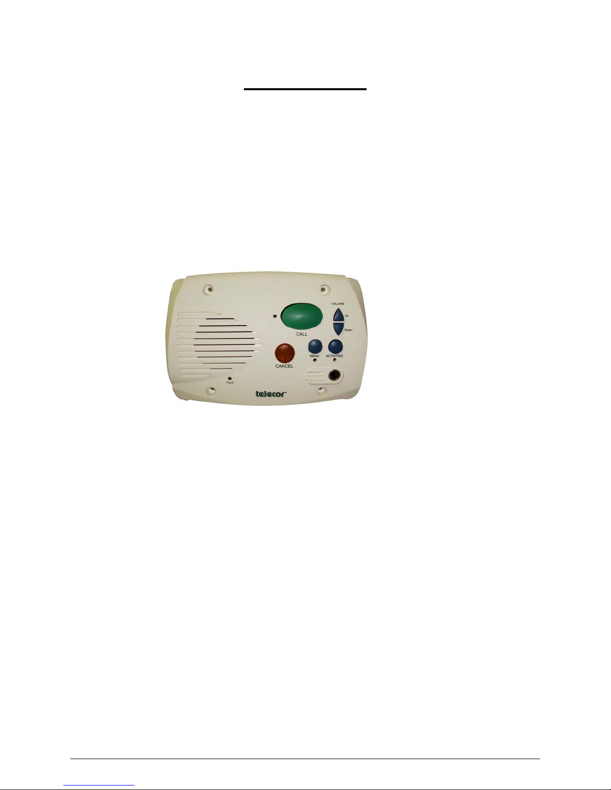
A.1 VS-600 Resident Unit Overview
The VS-600 Resident Unit is designed to allow hands-free and two-way communication between
the resident and an attendant. The Unit includes a Call Button to initiate calls to a designated
administrative staff location, a Call Cancel Button, a Volume Control, and Menu and Activity
Information Buttons. A built-in jack provides the ability to plug in a call cord, allowing the
resident to remotely initiate a call from the bedside.
Resident Unit (front
view)
The Unit is equipped with four status LEDs: Line, Activities, Menu, and Fault. The Line LED
illuminates when a call is initiated from the unit. When it illuminates in conjunction with the
Fault LED, it indicates a fault in the line. The Activities LED flashes when the Activities button
is pressed, and the Menu LED flashes when the Menu button is pressed to confirm selection.
The Fault LED illuminates and the unit signals a tone over the speaker to indicate a possible fault
in the Unit or the need for battery replacement.
The Unit can receive and decode signals from Wireless Pendants and Wireless Pull Cord Stations
and initiate calls to a designated administrative staff location. Each Pendant and Pull Cord
Station transmits a unique digital signal known only to the VS-600 Unit in the resident's room.
This provides assurance as to the exact origin of the call. The VS-600 has a reception range of up
to 50 feet (line of sight) from the Pendant or Pull Cord Station.
The Unit has an input provision for the connection of an external call-in device such as a Wired
Pull Cord Station, which provides call capabilities from resident bathrooms and showers. The
input can be assigned to one of six priority levels to clearly identify the origin of the call and
distinguish it from a cord call or a call initiated from the Unit’s call button.
With the addition of a Dome Light Module, the Unit has the ability to connect to a Dome Light
outside the resident's door, providing visual indication to staff of calls originating from the
resident's room. The Dome Light consists of three individual and different-colored lamps that
illuminate in distinct patterns to identify priority and the call-in device that the call originated
from.
A-2 Introduction
The Resident Unit is line powered from the single line station ports, eliminating the need for an
external power supply. The Unit is designed for installation into a standard 3-gang electrical
back box with 3-9/32" mounting centers.
A.2 Overview of Peripheral Devices
Described below are the peripheral devices that can function with the Resident Unit.
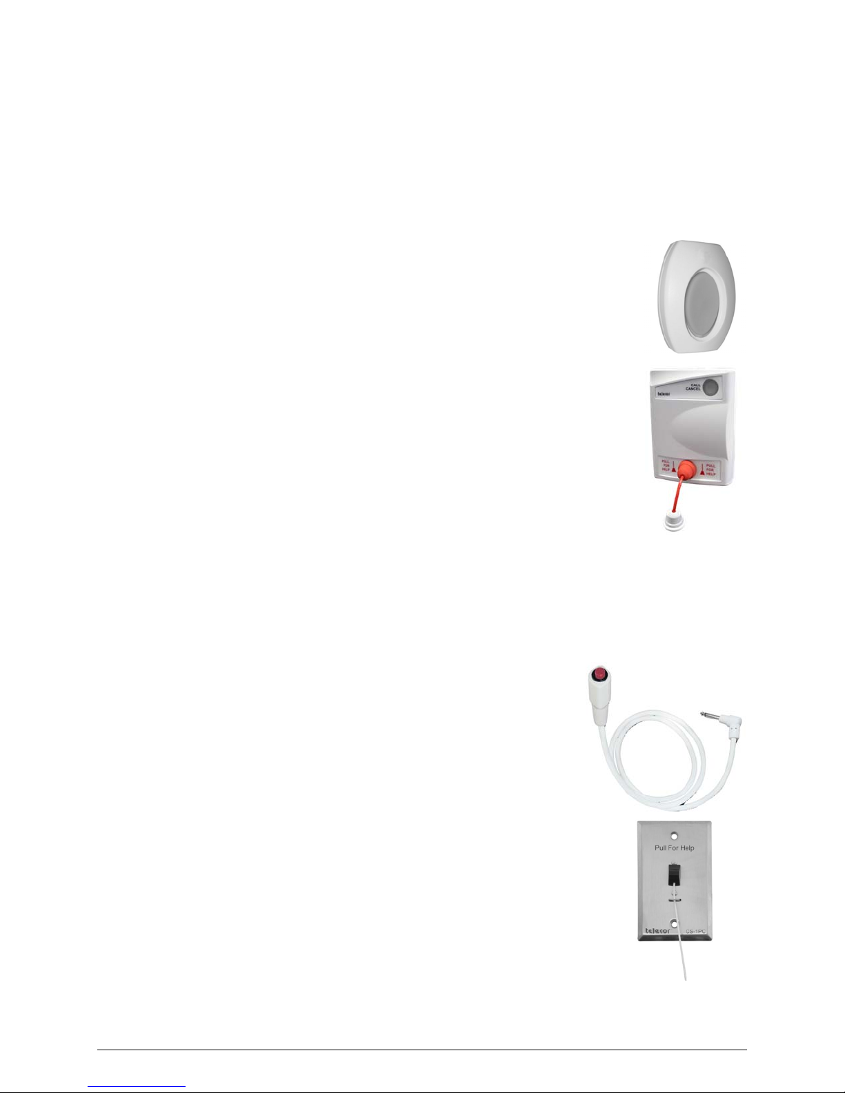
Wireless Pendant
The Wireless Pendant is worn by a VS-600 Resident user to allow him or her to
move freely about a room yet have the ability to place a call. Calls are initiated
by pressing a red call button on the Pendant.
Wireless Pull Cord Station
The Wireless Pull Cord Station offers the VS-600 Resident user the flexibility
of being able to position a Pull Cord Station anywhere in the room. This makes
it ideal for strategically positioning near furniture or in a bathroom or shower. It
makes it a cost effective "Add on" to the system without costly installation or
wiring upgrades.
Calls are initiated by pulling on the nylon pull cord. A call assurance LED
illuminates briefly and a soft tone sounds at the Station to confirm the
placement of the call. The call can be canceled at the Station by pressing a cancel button. An
illuminated LED and a tone at the Station confirm the cancellation of the call.
The Wireless Pull Cord Station is suitable for surface mounting directly to a wall. No backbox or
special mounting hardware is required.
NC-C1 Call Cord
A traditional Call Cord that plugs into the VS-600 Resident Unit to
provide the convenience of being able to initiate a call remotely from a
bedside.
Wired Pull Cord Station
The Wired Pull Cord Station provides call capabilities from resident
bathrooms and showers. The Station connects to the input on the VS-600
Resident Unit. Calls are initiated by pulling on the Station’s nylon call
cord, and annunciate at the attendant's telephone with a unique call priority.
The call can be canceled at the Resident Unit or from the attendant's
telephone.

VS-600 Resident Unit Manual A-3
NC1-LD3 Dome Light
The Dome Light is typically located outside the door of a room containing a
VS-600 Resident Unit to provide a visual indication of calls originating
from within the room. When a resident initiates a call, a LED in the Dome
Light illuminates. The Dome Light contains three LEDs with white, red and
green filters. Each lamp color represents a different call type that originates
from the Resident Unit’s call button or call cord, a Pull Cord Station, or a
Pendant.

VS-600 Resident Unit Manual B-1
B. VS-600 Programming
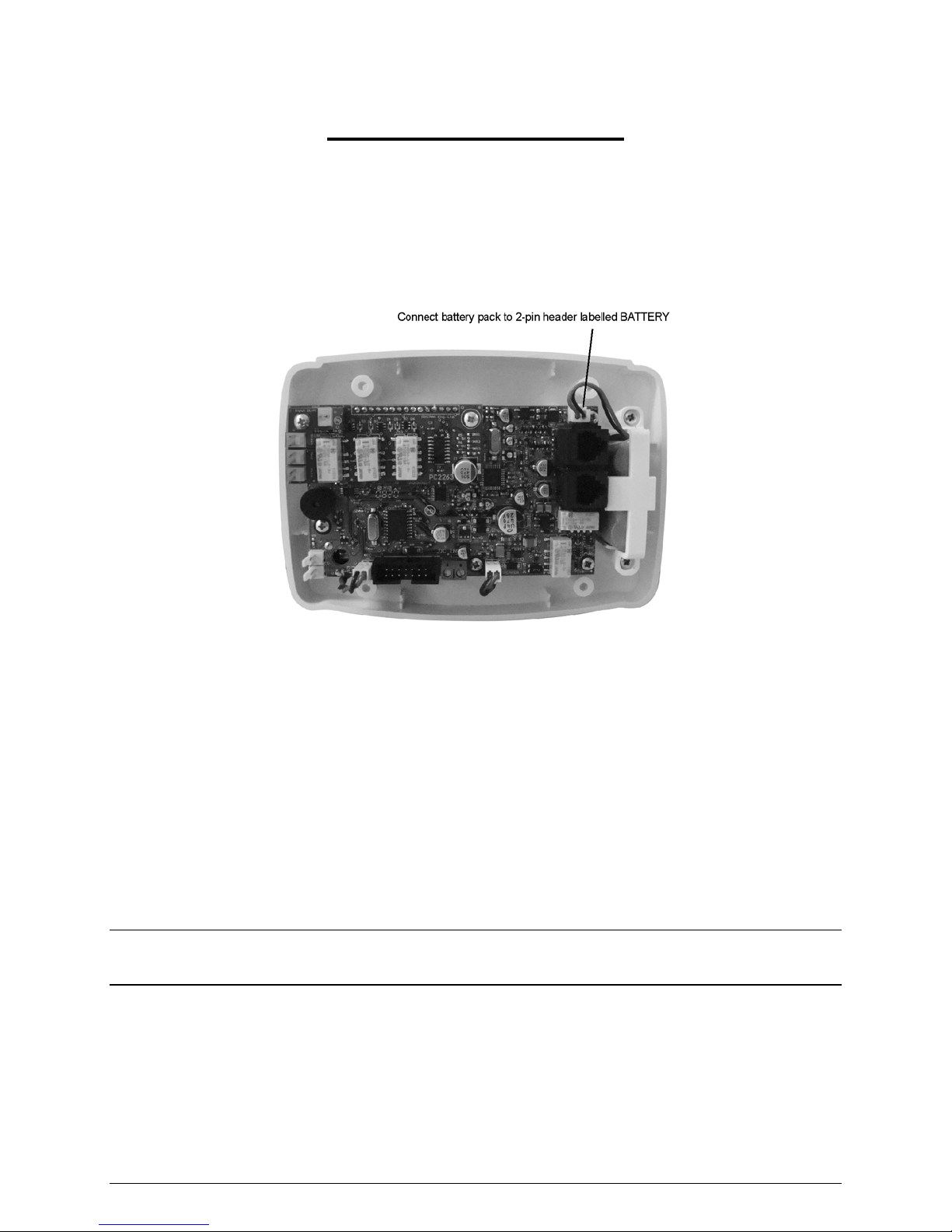
B.1 Resident Unit Diagnostic Procedure
Before programming and installing a Resident Unit, its diagnostic procedure first must be
completed. To run the diagnostic procedure, plug the battery pack onto the two-pin header
labeled BATTERY.
Once plugged in, the Unit should perform the following actions:
1. The four front LEDs and the Cancel button light up momentarily, then the line and fault
LEDs flash and the unit beeps. This indicates that the battery is functioning and the unit
has booted up properly.
2. The unit sounds three long beeps followed by three short beeps. This indicates that the
unit has gone through the cancellation routine, which prepares the unit for standby mode.
3. The unit checks if a telephone line has been connected to the upper LINE jack, closest to
the battery connector. After approximately five minutes, if a line still has not been
connected, the line and fault LEDs will flash and the unit will sound three short beeps.
Note: When the unit is in standby mode (idle, not in operation), it performs Diagnostic Check 3 every
five minutes. In working mode (the unit is in operation), it performs Diagnostic Check 3
continuously.
If all of the above actions have been performed, proceed with Resident Unit Programming
section B.2. If the unit fails to perform the above actions, contact Telecor VS-Care Technical
Support to request an RA.
B-2 VS-600 Programming
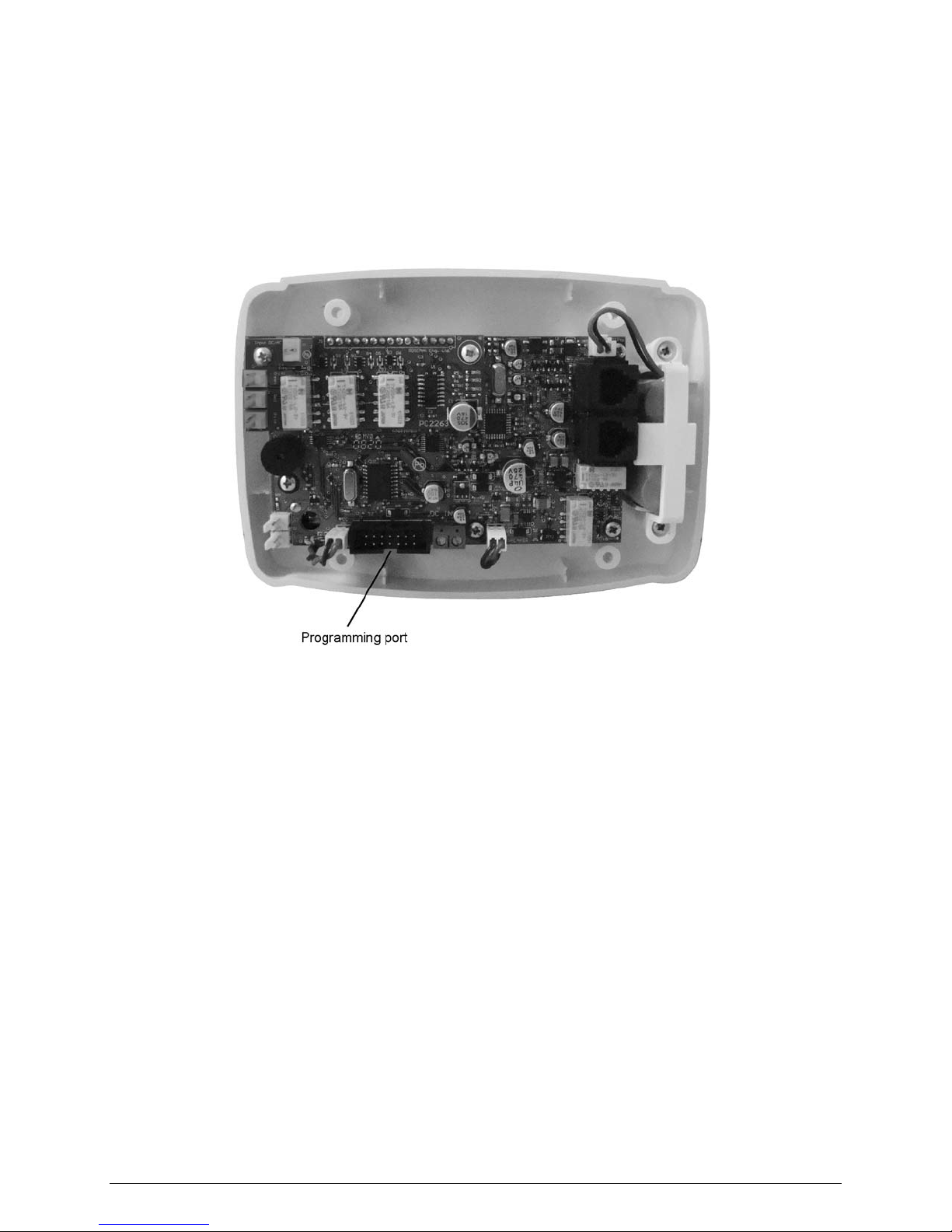
B.2 Configuring the Resident Unit for Programming
The VS-600 Resident Unit is programmed to operate in conjunction with the PBX using the
Resident Unit configuration software. The Resident Unit programming cable (sold separately)
plugs into the resident unit’s programming port and an available USB port of a PC running the
Resident Unit configuration software.
B.3 Using Resident Unit Configuration Software
When a resident unit or peripheral device such as a call cord or pendant makes a call, the resident
unit notifies the PBX what type of call device is making the call, and dials a number according to
the type of device making the call. This information is configured in the resident unit
configuration software and uploaded to the resident unit.
The Resident Unit configuration software is an application that works with Microsoft Windows
XP and Windows Vista®operating systems.
The Resident Unit configuration program consists of five tabs: Options, Prog./Config.,
Wireless Tool, Log File, and Speech Param. The Options tab is further divided into
Numbers, Supervision Numbers, and Misc (Miscellaneous) tabs. The Options, Prog./Config.,
and Speech Param. tabs contain settings for adjusting the behaviour of the resident unit. The
Wireless Tool and Log File tabs are used to download and review operational information from
the resident unit for troubleshooting.

VS-600 Resident Unit Manual B-3
B.3.1 Options Tab
The Options Tab shows the configuration options of the resident unit. The options tab is split
into two main areas: Set Number and Parameters. The Set Number area contains the dial
strings, priority and dome light settings for each call device and for the menu and activities
buttons. The Parameters area allows you to check the resident unit’s battery and internal clock.
The Options Tab is subdivided into three tabs: Numbers, Supervision Numbers, and Misc.
The Numbers Tab contains dial string, priority, and dome light settings for different call-in
devices. The Supervision Numbers Tab contains dial strings for situations triggered from
supervision. The Misc. tab contains dial string settings not covered in the previous tabs.
Use the Options Tab when you want to change dome light assignments, call phone destinations,
or call priorities.
B.3.1.1 Numbers Tab
The Numbers Tab contains the dial strings that the resident unit calls when a device makes a
call-in.
Options Tab,
Numbers Tab
Primary: The Primary boxes contain the primary dial string that the resident unit will call when
a particular device makes a call-in.
Secondary: The Secondary boxes contain the secondary or rollover dial string that the resident
unit will call when a particular device makes a call-in and the primary contact does not answer.
This number will only be dialed if the “Redial Primary num.” box is checked on the
Prog./Config. tab.
A dial string based on a required dial scheme must be entered into the Primary and Secondary
boxes. For an explanation of a dial string example, refer to Creating Dial Strings, section B.5.
Priority: A call device can be assigned a priority from 1 (highest) to 6 (lowest). For example, if
a resident presses the call button, it dials the assigned phone number and alerts the destination. If
the resident then triggers a higher-priority device, such as a call pendant, the call from the call
B-4 VS-600 Programming
button will be cancelled because of its lower priority, and the higher-priority device will dial its
assigned number.
Note: When a call device is triggered, there will be a delay of approximately five seconds before the
destination is alerted. If the resident activates a higher priority device within five seconds of
activating a lower priority device, the lower priority device will still be first to alert the destination.
Light:From the drop-down box, select which color in the dome light will illuminate when a call
is made by the call device. Options are none, red, green, or white.
Menu: The dial string that the resident unit will call when someone presses the Menu button.
Activities: The dial string that the resident unit will call when someone presses the Activities
button.
Battery: To check the resident unit’s battery, click Get below the Battery box. The current
battery voltage level will appear in the box. If the voltage level is below 3.6 V, replace the
battery.
Current Date/Time: The current date and time of your computer clock. Click Set to
synchronize the resident unit clock with your computer clock. The format is dd/MM/yy
HH:mm:ss where dd is the day, MM is the month, yy is the year, HH is the hour in 24-hour
format, mm is the minute, and ss is the second.
Device Date/Time: The date and time of the device’s internal clock. Click Get to retrieve the
resident unit’s internal time. The format is dd/MM/yy HH:mm:ss where dd is the day, MM is
the month, yy is the year, HH is the hour in 24-hour format, mm is the minute, and ss is the
second.
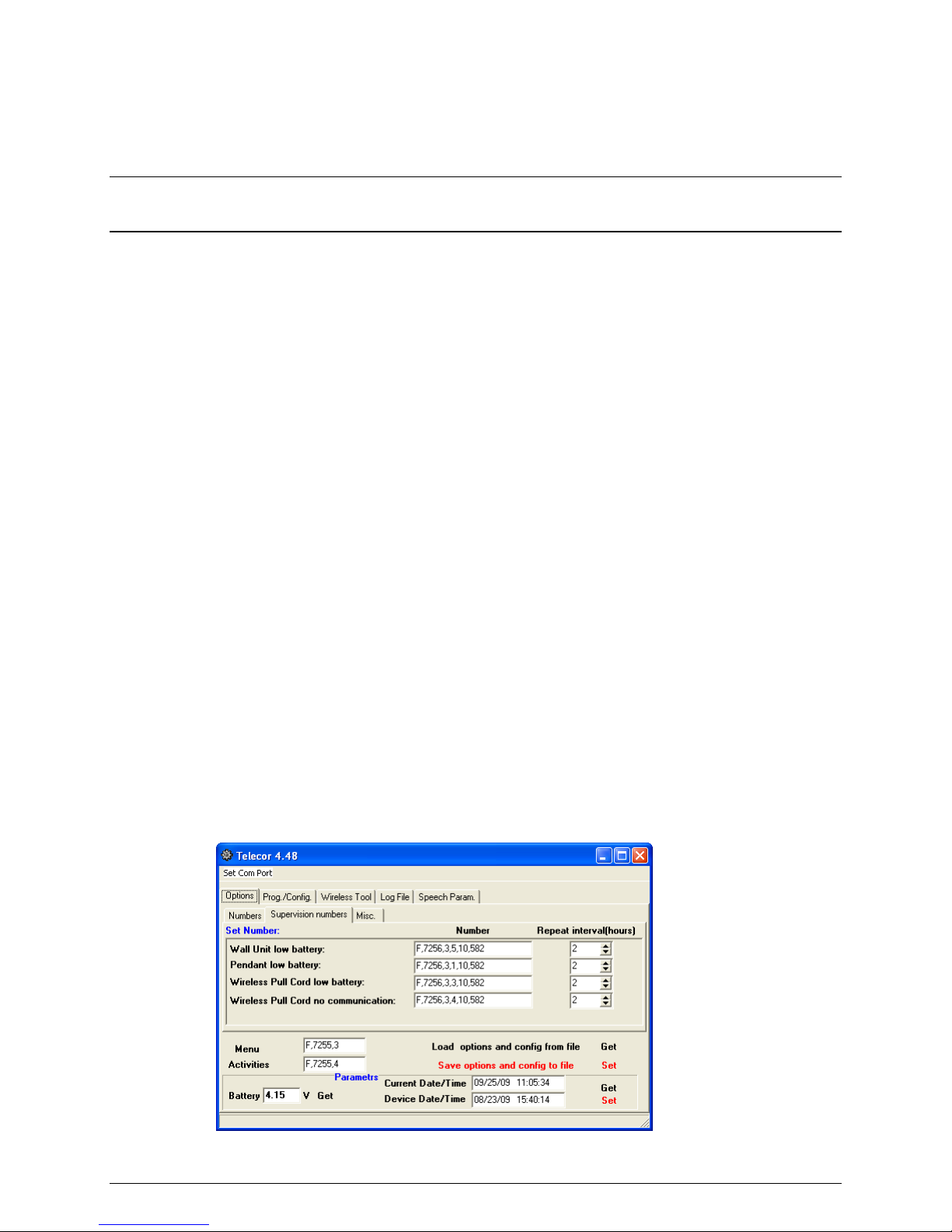
B.3.1.2 Supervision Numbers Tab
The Supervision Numbers Tab contains dial strings for situations triggered from battery or
device supervision.
Options Tab,
Supervision
Numbers
Wall Unit low battery: The dial string the unit will call when the resident unit’s battery is low.
VS-600 Resident Unit Manual B-5
Pendant low battery: The dial string the unit will call when a pendant’s battery is low.
Wireless Pull Cord low battery: The dial string the unit will call when a wireless pull cord
unit’s battery is low.
Wireless Pull Cord no communication: The dial string the unit will call when it loses contact
with the wireless pull cord.
Repeat interval (hours): The resident unit will redial the dial string after a certain number of
hours as long as the triggering condition is present.
For an explanation of a dial string example, refer to Creating Dial Strings, section B.5.
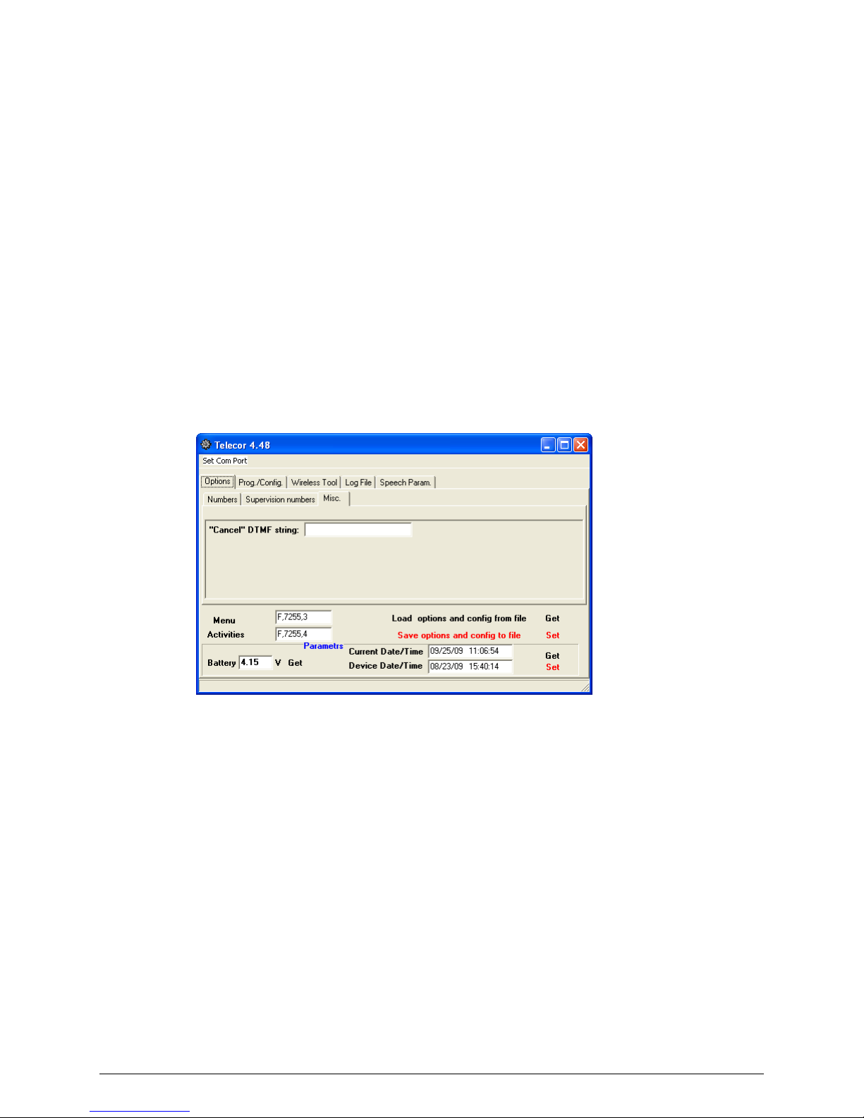
B.3.1.3 Misc. Tab
The Misc. tab contains dial string settings not covered in the other tabs.
Misc. Tab
“Cancel” DTMF string: The dial string the resident unit calls when the cancel button is pressed.
For an explanation of a dial string example, refer to Creating Dial Strings, section B.5.
B.3.2 Saving Programming Information to a File
You can save the current settings from the Options and Prog./Config. tabs to a file. This is
useful for quickly programming multiple resident units with the same settings.
To save the current configuration settings to a file, click Save options and config to file, type a
file name for your configuration file, then click Save.
To load configuration settings from a file, click Load options and config from file, select your
configuration file, then click Open.
Click Get beside Load options and config from file to download the settings from the resident
unit.
B-6 VS-600 Programming
Click Set beside Save options and config to file to upload the current settings to the resident
unit.
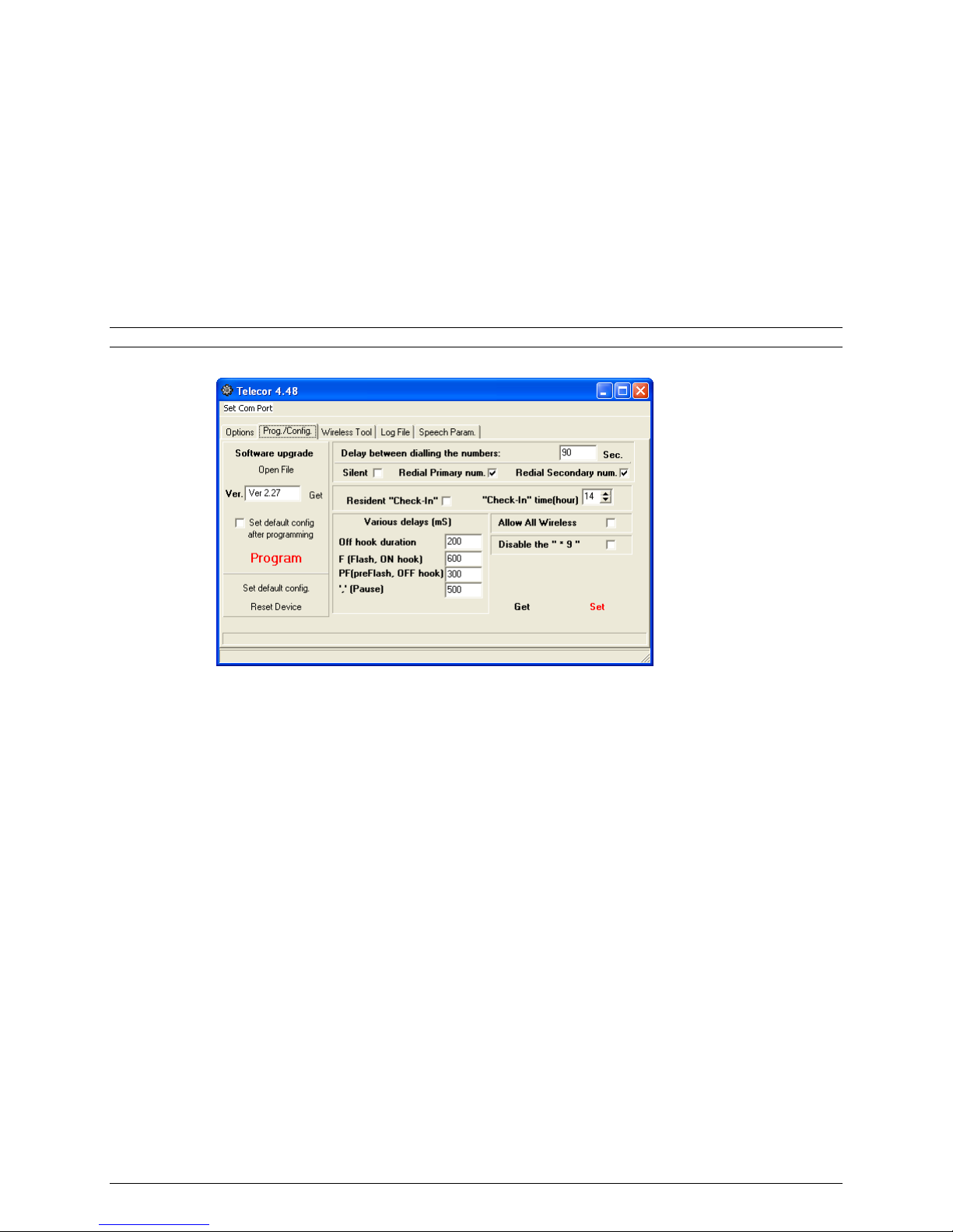
B.3.3 Prog./Config. Tab
The Prog./Config. Tab contains programming and configuration settings for the resident unit.
Use this tab to change the desired behaviour when a call goes unanswered, to upgrade the
resident unit software, to configure the unit for use in a common area, or configure whether a call
from the unit can be cancelled by dialling *9 at the destination.
Note: In a majority of installations, these settings do not need to change.
Prog./Config.
Tab
Software upgrade: This section is used to upgrade the resident unit software. It should not be
used unless instructed to do so by Telecor Technical Support.
Delay between dialing the numbers: After dialing a number, the number of seconds to wait
before dialing the secondary or rollover number if the call is unanswered.
Silent: Check the box to make the resident unit dial the phone voice server silently when a
device makes a call. If unchecked, you will hear the DTMF tones while the resident unit dials a
call.
Redial Primary num. (Redial secondary number if primary number does not answer):
Check this box to enable the device to redial or rollover to the secondary number after dialing the
primary number if the primary number does not answer. See the table on the next page for an
explanation of this feature.
Redial Secondary num. (Redial primary number if secondary number does not answer):
Check this box to enable the device to redial or rollover to the primary number after dialing the
secondary number if the secondary number does not answer. See the table on the next page for
an explanation of this feature.

VS-600 Resident Unit Manual B-7
The following table describes the effects of checking the Redial Primary or Redial Secondary
boxes:
Redial
Primary Redial
Secondary Result
1. Resident unit dials primary number.
2. Resident unit waits for the call to be answered or for the time in delay
to elapse.
3. If the call is unanswered, the resident unit ends the call (hangs up).
;
1. Resident unit dials primary number.
2. Resident unit waits for the call to be answered or for the time in delay
to elapse.
3. Resident unit dials secondary number.
4. Resident unit waits for the call to be answered or for the time in delay
to elapse.
5. If the call is unanswered, the resident unit ends the call (hangs up).
;1. Resident unit dials primary number.
2. Resident unit waits for the call to be answered or for the time in delay
to elapse.
3. If the call is unanswered, the resident unit ends the call (hangs up).
;;
1. Resident unit dials primary number.
2. Resident unit waits for the call to be answered or for the time in delay
to elapse.
3. Resident unit dials secondary number.
4. Resident unit waits for the call to be answered or for the time in delay
to elapse.
5. If the call is unanswered, the resident unit dials the primary number
again (goes back to step 1).
Resident “Check-In”: Not used.
“Check-In” time(hour): Not used.
Various Delays (ms): These values are set by default and should not be changed unless
instructed to do so by Telecor Technical Support.
Allow All Wireless: Check this box to allow the resident unit to accept calls from all wireless
devices without needing them to be programmed first. See section B.6 for more information
about configuring a resident unit for use in a common area.
Disable the “ * 9 ”: Check this box to disallow someone from cancelling a call from the resident
unit by dialing *9 at the destination station. Note that *9 can still be used to interrupt the playing
of menu entrées or activity schedules.
Click Get to download the settings from the resident unit.
Click Set to upload the current settings to the resident unit.

B-8 VS-600 Programming
B.3.4 Wireless Tool Tab
The Wireless Tool Tab allows you to view a list of wireless devices programmed on the resident
unit. A resident unit can support up to 4 wireless pendants and 4 wireless pull cords, for a total
of 8 devices.
If the maximum number of devices are programmed in the resident unit, one must be removed
before a new one can be programmed. Use this tab to deprogram devices from the resident unit.
Wireless Tool
Tab
Click Get all used to download a list of devices programmed on the resident unit. The list
shows the devices’ serial numbers.
To remove a device, select a device in the list and click Remove selected to remove the device.
To remove all the programmed devices from the resident unit, click Remove all.
For information about programming wireless pendants and pull cords in the resident unit, refer to
section C.6.
The resident unit can be configured to accept calls from all wireless devices without needing
them to be programmed first. See section B.6 for more information about configuring a resident
unit for use in a common area.
VS-600 Resident Unit Manual B-9
B.3.5 Log File Tab
The Log File Tab allows you to review the resident unit’s log file. The log file is used for
troubleshooting, but you will not need to access this tab in most situations. The log file stores
the dates, times, and descriptions of the last 50 events.
Log File Tab
Click Load to download the log file from the resident unit.
Click Save to File to save the log file to a disk. Type a file name, then click Save.
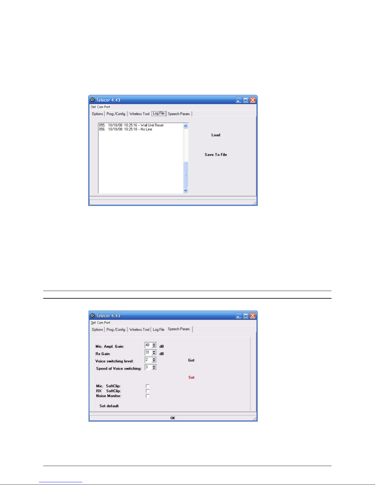
B.4 Speech Param. Tab
The Speech Param. Tab allows you to adjust the resident unit’s audio settings. Use this tab to
adjust microphone volume, speaker volume, or voice switching settings.
Note: In a majority of installations, these settings do not need to change.
Speech Param.
Tab
Mic. Ampl. Gain: Microphone amplifier gain. This value ranges from 39 to 54 dB and the
default is 48 dB. Click the up or down arrows to increase or decrease the microphone volume.

B-10 VS-600 Programming
Rx Gain: Speaker gain. This value ranges from 22 to 37 dB and the default is 31 dB. Click the
up or down arrows to increase or decrease the speaker volume.
Voice switching level: The noise level required to switch the speaker from talk to listen. This
value ranges from from 1 to 4 and the default is 2. Click the up or down arrows to adjust the
level.
Speed of Voice switching: Controls the speed of the speaker switching from talk to listen. This
value ranges from 1 to 4 and the default is 3. Click the up or down arrows to adjust the
switching speed.
Mic. SoftClip: Not used.
RX SoftClip: Not used.
Noise Monitor: Not used.
Click Set default to restore the settings to their default values.
Click Get to download the settings from the resident unit.
Click Set to upload the current settings to the resident unit.
B.5 Creating Dial Strings
This section contains an explanation of a sample dial string when used with a Telecor PBX.
In this example, the dial string in the Primary or Secondary column for a device is made up of six
comma-separated parts. The comma indicates a half-second pause. The dial string lets the
resident unit notify the phone voice server when a device makes a call. Below is an example
primary dial string for the call button:
Dial String part 1: The dial string begins with F, which performs a hook flash.
Dial String part 2: The resident unit sends the call to an Auto Attendant. In the example,
7256 sends the call to Auto Attendant 19.
Dial String part 3: Notes whether the call is a primary or secondary/rollover call. In the
example, 1is for a primary call and 2is for a secondary or rollover call.
This manual suits for next models
2
Table of contents
Other Telecor Conference System manuals

Popular Conference System manuals by other brands


Rath
Rath Refuge Command Center Installation and operation manual

Cisco
Cisco TelePresence IX5200 installation guide

Cisco
Cisco TelePresence ISDN Link Administrator's guide

VADDIO
VADDIO ConferenceSHOT AV Complete manual

FUTABA
FUTABA R7114SB user manual

Barco
Barco ClickShare CX-20 set Gen 2 installation manual