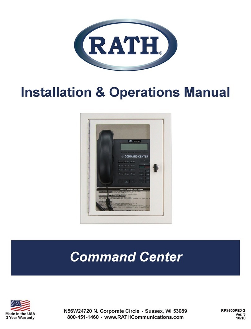
Rath Refuge Command Center User manual

Installation
&
Operations
Manual
N56 W24720 N. Corporate Circle Sussex, WI 53089
800-451-1460 262-246-4828 (fax)
www.rathmicrotech.com www.area-of-refuge.com 12/13
Made in the USA
3 Year Warranty
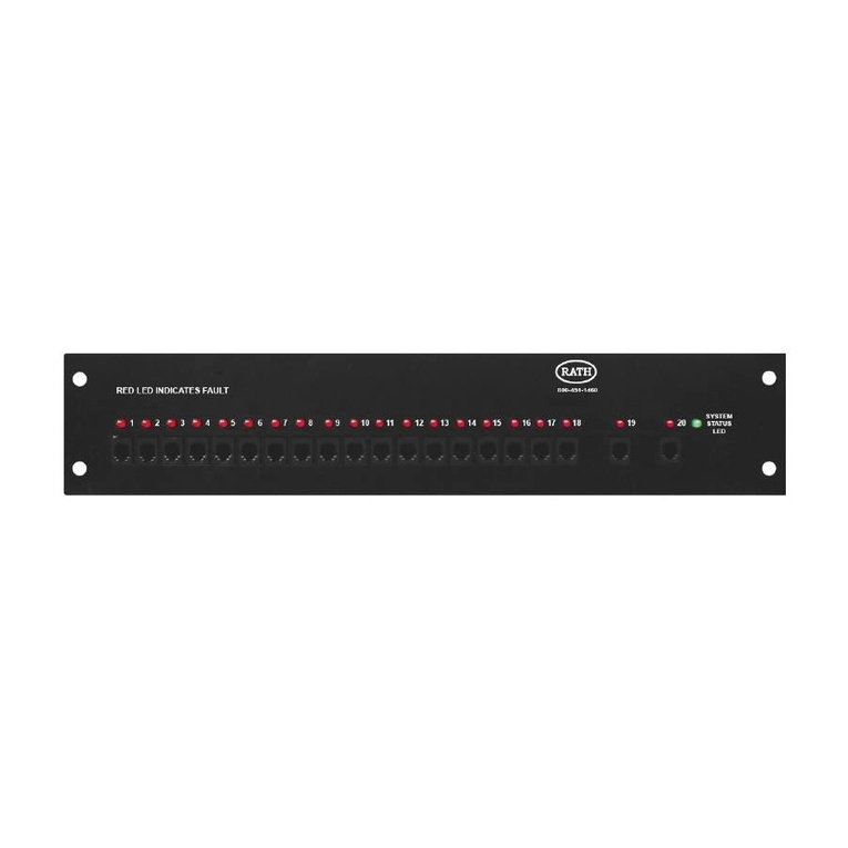
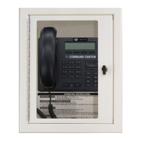
Refuge Command Center
RP8500PBX
Rev. 3
www.rathmicrotech.com www.area-of-refuge.com

Welcome to Rath.
Thank you for purchasing the Rath Refuge Command Center.
We take great pride in our products, service and support. Our #1 mission is customer satisfaction.
When evaluating emergency communication systems, you can rely on Rath to continually provide
Innovative Thinking, Design and Value.
Thank you for your business.
Tom Touchett, President
Installation . . . . . . . . . . . . . . . . . . . . . . . . . . . . . . . .
Distribution Module Programming . . . . . . . . . . . . .
Phone Programming . . . . . . . . . . . . . . . . . . . . . . . .
Operating Instructions . . . . . . . . . . . . . . . . . . . . . . . ..
Wiring Diagrams . . . . . . . . . . . . . . . . . . . . . . . . . . .
Table of Contents
Page 2
Page 3
Page 4
Page 4
Page 5-7
www.rathmicrotech.com www.area-of-refuge.com
N56 W24720 N. Corporate Circle Sussex, WI 53089
800-451-1460 262-246-4828 (fax)
www.rathmicrotech.com www.area-of-refuge.com

pg. 2
Installation
1. Install the Silver Stand on the back of the Base Station Handset for desk mount. For wall mount units
install cabinet on wall in desired location.
2. Mount the Distribution Module in an approved location.
3. Take one end of the Distribution Module Power Cable and Plug it into the DC Adapter Port on the
Distribution Module and the other end into a 110 volt AC outlet with Battery Backup or the Rath
Model RP7700104 (12-36 Zone) or Model RP7700105 (56-112 Zone).
4. If 12-36 Zone Remove screws on back of unit and take cover off to expose internal ports.
6. Connecting Phones to the Distribution Module
A. Phones connect to the Distribution Module via the special wiring harnesses.
7. Power On the Distribution Module
www.rathmicrotech.com www.area-of-refuge.com
5. Connecting Base Station to Distribution Module
B. Plug the RJ45 connectors of the wiring harness into the ports of the Module following
C. Wire the Phones to single pair 24 or 22 gauge cabling.
the Diagrams on Pages 6-10. (The number of ports on the Module will depend
on the number of Phones needed for your installation
D. Connect the cabling to the Distribution Module wiring harness following Wiring Diagrams
for proper port numbering and color coding
E. For Example: Phone 1 should connect to Port 1 via the Cable 1 harness.
Cable 1 is marked with a Dark Blue band. The connection will be made through the Blue and
Blue/White wiring in Cable 1
*Note: The maximum cable length to Phones is 112,500’ for 22 GA cable and 70,300’ for
24 GA cable.
A. The Base Station connects to Card 1, of the Distribution Module (see pages 6 & 8)
B. Use the Blue and White/Blue Striped Wiring in Cable 5 to make the connection
C. Cable 5 is marked by a Light Blue band
D. If additional wire needs to be added to the Cable 5 harness to connect the Command Center to
the Termination Module, use a single pair 24 or 22 gauge cable.
*Note:The maximum cable length to Command Center is 6200’ for 22 GA cable and 3900’
for 24 GA cable.
E. If Base Station includes auxillary Button Module, or Secondary Base Station connect to the Distribution:
1. Button Module 1 or Secondary Base Station (12-16 Zone): On DKP Port of card 1
2. Button Module 2 and/or a Secondary Base Station (28-112 Zone) with Button
Module per the following:
Module(s): Locate additional DKP port(s) on additional card and wire out with appropriate
pair for extenstion on port. (Will be either blue, blue-white or orange, orange-white)
wire out with orange, orange-white pair

pg. 3
Distribution Module Programming
Programming Time Zone
1. Enter programming mode
A. Dial 1#91
2. 1002 (time zone code)
Eastern 111
Central 112
Mountain 113
Pacific 114
3. Touch Check Mark Button in middle of Base Station Phone.
4. Exit programming – Dial 00 - Touch Check Mark
Programming Month – Day – Year
1. Enter programming mode
A. Dial 1#91
2. 1001 (Month – Day- Year)
Example: 1001 02152011 (February 15 2011)
3. Touch Check Mark
4. Exit Programming – Dial 00 - Touch Check Mark
Programming Time
1. Enter programming mode
A. Dial 1#91 1111
2. 1003 (Hours – Min – Sec)
Example: 1003 143000 (2:30 p.m.)
3. Touch Check Mark
4. Exit Programming Dial 00 - Touch Check Mark
www.rathmicrotech.com www.area-of-refuge.com
*Note: All programming for the Distribution Module will be done from the Base Station Handset.
B. Enter Password: 7284

pg. 4
Base Station Operating Instructions
Indicator Status
1. Blue LED Light – Phone calling Base Station
2. Blue LED Light Flashing – Phone is on Hold
3. Red LED Light – Phone calling Outside the building
4. Base Station LCD display will show extensions calling into unit
Answering Call at Base Station
1. Pick up Handset or press Speakerphone Button on Base Station to answer first incoming call
2. If multiple calls, press Blue LED Light of next desired Phone to talk (this will place original call on Hold
or you can press the Blue LED Light to place call on Hold)
3. To disconnect individual Phones press *, #. If all Phones have been answered Hang Up to
disconnect all calls
Calling into a Phone
1. Pick up Handset or press Speakerphone Button on Base Station
2. Press button on Base Station corresponding to desired phone
Joining an Existing Conversation between Phone & an Outside Party
1. Pick up Handset or press Speakerphone Button on Base Station
2. Press Red LED Light of the desired Phone, you will get a busy signal, Dial 5
3. Outside Party can either stay in conversation or hang up at this time
Call the Last Phone that Dialed the Base Station
1. Pick up Handset or press Speakerphone Button on Base Station
2. Dial 1092
www.rathmicrotech.com www.area-of-refuge.com
Phone Programming
Connect the Phone to an active Port on Distribution Module and follow the instructions below
Phone Calls the Base Station
1. For the Phone to call the Base Station, it must be programmed to dial 0
2. Follow the directions that came with the Phone to program Memory Location 1 to dial 0
Phone Calls a Number Outside of the Building
1. For the Phone to call a number outside the building, it must be programmed to first dial 9, Pause, Pause
then the phone number
2. Follow the directions that came with the Phone to program Memory Location 1 to dial 9, Pause, Pause
then digits of the outside phone number
Phone Calls the Base Station First then a Number Outside of the Building
1. The Phone can be programmed to call the Base Station first and if that call is not
answered, call an outside number.
2. Follow the directions that came with the Phone to program Memory Location 1 to dial 0.
3. Then program Memory Location 2 to dial 9, Pause, Pause then the outside phone number.
Phone Location Message
1. When programming the Phone to play a location message, it is recommended that
two pauses be added to the end of the programmed dialed number.
For example: For dialing the Base Station, program the Phone to dial 0, Pause, Pause

pg. 5
1 Wire Pair Per Phones
www.rathmicrotech.com www.area-of-refuge.com
SOLID LIGHT: CALLING
BLINKING LIGHT: RECEIVED
PHONEHELP
Power Supply
w/UPS
SOLID LIGHT: CALLING
BLINKING LIGHT: RECEIVED
PHONEHELP
SOLID LIGHT: CALLING
BLINKING LIGHT: RECEIVED
PHONEHELP
SOLID LIGHT: CALLING
BLINKING LIGHT: RECEIVED
PHONEHELP
e
Base
Station
Distribution
Module

Card Wiring for 12-36 Zone System
A. On back of unit, remove two screws in top left and right and slide cover off unit to expose internal cards.
B. On top of each card there is a table indicating what each port on that card is.
1. SLT is the port used for connecting Emergency Phones
2. DKP is the port used for connecting Base Station phone(s)
3.TWT is the port used for outside telco line
C.The first card installed will always be:
1. Port 1: (S01-S04) Connection for 4 Emergency Phones
2. Port 2: (S05-S06) Connection for 2 Telco Lines
3. Port 3: (S07-S08) Connection for 2 Base Station Phones
D. Plug RJ45 of wiring harness into appropriate port (See wiring diagram below)
Color Extension Number
S01-S04 S05-S06 S07-S08
Blue - (Blue & White)
Orange - (Orange & White)
Green - (Green & White)
Brown - (Brown & White)
2001
2002
2003
2004
Blue - (Blue & White)
Orange - (Orange & White)
TELCO LINE 1
TELCO LINE 2
Blue - (Blue & White)
Orange - (Orange & White)
AOR COMMAND CENTER
SECONDARY AOR
COMMAND CENTER
(Optional)
(Connect to Red and Green of Phone Cord)
www.rathmicrotech.com www.area-of-refuge.com
pg. 6
For additional extensions on SLT ports follow scheme below:
2005: Blue, Blue-White
2006: Orange, Orange-White
2007: Green, Green-White
2008: Brown, Brown-White
2009: Blue, Blue-White
2010: Orange, Orange-White
2011: Blue, Blue-White
2012: Orange-Orange, White
2013: Blue, Blue-White
2014: Orange, Orange-White
2015: Green, Green-White
2016: Brown, Brown-White
2017: Blue, Blue-White
2018: Orange, Orange-White
2019: Blue, Blue-White
2020: Orange, Orange-White
2021: Blue, Blue-White
2022: Orange, Orange-White
2023: Green, Green-White
2024: Brown, Brown-White
2025: Blue, Blue-White
2026: Orange, Orange-White
2027: Blue, Blue-White
2028: Orange, Orange-White
2029: Blue, Blue-White
2030: Orange, Orange-White
2031: Green, Green-White
2032: Brown, Brown-White
2033: Blue, Blue-White
2034: Orange, Orange-White
2035: Blue, Blue-White
2036: Orange, Orange-White
*Refer to top of cards to see what type of port and how many extentions are off of them

Card Wiring for 56-112 Zone System
A. Each card installed in 56-122 zone units will have 6 ports on each card.
B. Each slot is labeled below indicating what type of slot it is.
1. S00-S00 is the port(s) used for connecting Emergency Phones
2.The TD(1-2)(3-4) with a dot under the “D” is the port used for connecting Base Station phone(s)
3.TD(1-2)(3-4) with a dot under the“T” is the port used for outside telco line
C.The first card installed will always be:
1. Port 1: (T1-2) Connection for up to 2 outside Telco Lines
2. Port 2: (D1-2) Connection for Base Station Phone and 64 Button Console (If Using)
3. Port 3: (S01-S04) Connection for 4 Emergency Phones
4. Port 4: (S05-S08) Connection for 4 Emergency Phones
5. Port 5: (S09-S12) Connection for 4 Emergency Phones
6. Port 6: (S13-S16) Connection for 4 Emergency Phones
D. Plug RJ45 of wiring harness into appropriate port (See wiring diagram below)
www.rathmicrotech.com www.area-of-refuge.com
pg. 7
S01-S04S05-S08S09-S12S13-S16
TD 1-2 3-4 TD 1-2 3-4
2001
2002
2003
2004
(Connect to Red and Green of Phone Cord)
2005
2006
2007
2008
(Connect to Red and Green of Phone Cord)
2009
2010
2011
2012
(Connect to Red and Green of Phone Cord)
2013
2014
2015
2016
(Connect to Red and Green of Phone Cord)
E. For additional Cards follow pattern below
2017: Blue, Blue-White
2018: Orange, Orange-White
2019: Green, Green-White
2020: Brown, Brown-White
2021: Blue, Blue-White
2022: Orange, Orange-White
2023: Green, Green-White
2024: Brown, Brown-White
2025: Blue, Blue-White
2026: Orange, Orange-White
2027: Green, Green-White
2028: Brown, Brown-White
2029: Blue, Blue-White
2030: Orange, Orange-White
2031: Green, Green-White
2032: Brown, Brown-White
2033: Blue, Blue-White
2034: Orange, Orange-White
2035: Green, Green-White
2036: Brown, Brown-White
2037: Blue, Blue-White
2038: Orange, Orange-White
2039: Green, Green-White
2040: Brown, Brown-White
2041: Blue, Blue-White
2042: Orange, Orange-White
2043: Green, Green-White
2044: Brown, Brown-White
2045: Blue, Blue-White
2046: Orange, Orange-White
2047: Green, Green-White
2048: Brown, Brown-White
2049: Blue, Blue-White
2050: Orange, Orange-White
2051: Green, Green-White
2052: Brown, Brown-White
2053: Blue, Blue-White
2054: Orange, Orange-White
2055: Green, Green-White
2056: Brown, Brown-White
2057: Blue, Blue-White
2058: Orange, Orange-White
2059: Green, Green-White
2060: Brown, Brown-White
2061: Blue, Blue-White
2062: Orange, Orange-White
2063: Green, Green-White
2064: Brown, Brown-White
2065: Blue, Blue-White
2066: Orange, Orange-White
2067: Green, Green-White
2068: Brown, Brown-White
2069: Blue, Blue-White
2070: Orange, Orange-White
2071: Green, Green-White
2072: Brown, Brown-White
2073: Blue, Blue-White
2074: Orange, Orange-White
2075: Green, Green-White
2076: Brown, Brown-White
2077: Blue, Blue-White
2078: Orange, Orange-White
2079: Green, Green-White
2080: Brown, Brown-White
2081: Blue, Blue-White
2082: Orange, Orange-White
2083: Green, Green-White
2084: Brown, Brown-White
2085: Blue, Blue-White
2086: Orange, Orange-White
2087: Green, Green-White
2088: Brown, Brown-White
2089: Blue, Blue-White
2090: Orange, Orange-White
2091: Green, Green-White
2092: Brown, Brown-White
2093: Blue, Blue-White
2094: Orange, Orange-White
2095: Green, Green-White
2096: Brown, Brown-White
2097: Blue, Blue-White
2098: Orange, Orange-White
2099: Green, Green-White
2100: Brown, Brown-White
2101: Blue, Blue-White
2102: Orange, Orange-White
2103: Green, Green-White
2104: Brown, Brown-White
2105: Blue, Blue-White
2106: Orange, Orange-White
2107: Green, Green-White
2108: Brown, Brown-White
2109: Blue, Blue-White
2110: Orange, Orange-White
2111: Green, Green-White
2112: Brown, Brown-White
Other Rath Conference System manuals
Popular Conference System manuals by other brands

TANDBERG
TANDBERG MPS 200 Administrator's guide

Huawei
Huawei MA5833-BS60 Commissioning Guide

COMMUNICATIONS-APPLIED TECHNOLOGY
COMMUNICATIONS-APPLIED TECHNOLOGY ICRI-E Setup and operating procedures

Samsung
Samsung SyncMaster VC240 reference guide

Panasonic
Panasonic KX-HTS Series Setup Reference Guide

Polycom
Polycom RealPresence Group Series setup sheet

Polycom
Polycom SoundStation IP 3000 user guide

Advanced Wireless Communications
Advanced Wireless Communications AWR-CB2200 Operator's manual

Pointmaker
Pointmaker CR-100 quick start guide

Aethra
Aethra AVC500 Use and installation manual

Relyon plasma
Relyon plasma Brush operating instructions

Blaupunkt
Blaupunkt CKT 1 Operating and installation instructions