TeleCorder TCwL-B4 User manual

TeleCorder
TCwL-B4
Voice Logging
Recorder
TeleCorder
Four Channels — Internal Hard Drive stores the most recent 11,000
Conversation Hours — Access recordings via USB & LAN
User Manual
Version 2.43, Revision 4, USA

TeleCorder # TCwL-B4, V2.43, Revision 4, USA 1
Table of Contents Page 1
Tele
Corder
Model TCwL-B4 — Description ................................ 3
Recorder Features.............................................................................................. 3
Supplied Accessories......................................................................................... 3
1. Identify the Front and Rear Panel Connections................................ 4
2. Cable Connections and Testing........................................................... 4
2.1 Connecting to Phone Lines and other Audio Sources ................................. 4
2.1.1 Connection for 4 channels with TCwL-B4................................. 4
2.2 Power Connection.......................................................................................... 5
2.3 Installing Software & Connecting to a PC (Win-2000/XP/Vista/Win-7).. 5
3. Setup via USB Connection to PC ....................................................... 6
3.1 Open Software................................................................................................ 6
3.2 Recording Process.......................................................................................... 6
3.3 Setting for Phone Line or Voice Activated Recording (VAR)................... 7
3.4 VAR Settings (Voice Activated Recording)................................................. 7
3.5 Setting Channels for Operation in VAR Mode........................................... 7
3.6 Configuring Tele
Corder
using a PC........................................................... 7
3.6.1 Channel/Port Setup ................................................................. 8
3.6.2 VAR Voltage Threshold (Voice Activated Recording).......... 8
3.6.3 Turn Off Delay Time (VAR Space Time) .............................. 8
3.6.4 VAR Timeout............................................................................ 8
3.6.5 Save or Delete Recordings Less Than 8 Seconds..................... 9
3.6.6 Hardware Information............................................................... 9
3.6.7 Date/Time Setting and Calibrating Time Keeping Accuracy........... 9
3.6.8 Audio Recording Mode (Quality of Recordings) ................... 10
3.6.9 Limitation for List Displaying ................................................ 10
3.6.10 Caller ID Detection Settings ...................................................10
3.6.11 About TeleCorder PC Software............................................ 10
3.6.12 Quit Hardware Information & Settings................................... 10
3.6.13 Notes for Setup via PC............................................................ 10
4. Setup for Accessing the Tele
Corder
via LAN................................. 11
4.1 Reflash Utility —Application to Find or Change IP Address ............. 11
4.1.1 Reflash Utility Application Notes (Version 1.55)................... 12
4.2 Settings that can only be accessed via LAN ........................................... 13
5. Managing and Playing the Recordings ............................................ 14
5.1 Managing and Playing Recordings with a PC ......................................... 14
5.1.1 Connection.................................................................................. 14
5.1.2 Using the Utility Software.......................................................... 14
5.1.3 Refreshing the List of Recordings.............................................. 15
5.1.4 Re-Order the List of Recordings ................................................ 15
5.1.5 Find Recordings using Search Criteria.................................... 15

2 TeleCorder # TCwL-B4, V2.43, Revision 4, USA
5.1.6 Files, Information .................................................................... 16
5.1.7 Conversion of Recordings and Saving to a PC........................ 16
5.1.8 Print and Save the List of Records .......................................... 17
5.1.9 Deleting Recordings from TeleCorder.................................. 17
5.1.10 Hardware, Info & Settings - Access to Hardware Menu......... 17
5.1.11 Hardware Information ............................................................. 18
5.1.12 Date and Time Setting............................................................. 18
5.1.13 Set Channels to Voice Activated Recording (VAR) ............... 18
5.1.14 VAR Voltage Threshold.......................................................... 18
5.1.15 VAR Turn Off Delay............................................................... 18
5.1.16 VAR Time Out ........................................................................ 18
5.1.17 Save VAR less than 8 seconds or less than 3 DTMF #........... 18
5.1.18 Audio Recording Mode (Quality of Recordings)...................... 18
5.1.19 Limiting the List of Displayed Recordings ............................. 19
5.1.20 Caller ID Detection Settings.................................................... 19
5.1.21 About TeleCorder PC Software............................................. 19
5.1.22 Quit or Exit the Hardware Info & Settings Window................. 19
5.1.23 Lock/Unlock with Password.................................................... 19
5.1.24 Modify Password....................................................................... 19
5.1.25 USB Password........................................................................... 19
5.1.26 Play Recordings from the List and Copy to PC......................... 20
5.1.27 Monitoring Port Activity and Listening over LAN................... 21
6. Guarantee & Liability .......................................................................... 22
7. Specifications........................................................................................ 22
8. Contact Information for Support and Service................................... 22
9. Popular Accessories .............................................................................. 23
TSA-3LM Adapter for Connecting to aPhone Set at Handset Jack ......... 23
TSA-SLM Adapter for Connecting to aPhone Set, with On/Off Switch.. 23
TSA-2A1 Adapter for Connecting to a Phone Set, with Audio Mixer... 23
RSA-U5 Radio Adapter,with Amplifiers,Mixing,and PTT Sensing ... 23
MOD-SC Adapter for converting modular phone plug to mini plug...... 23
10. Notes ................................................................................................... 24
11. User Notes .......................................................................................... 24

TeleCorder # TCwL-B4, V2.43, Revision 4, USA 3
Tele
Corder
Voice Logging Recorder — Model TCwL-B4
The TeleCorder model TCwL-B4 can simultaneously record analog audio from one to four phone
lines or other line-level analog audio sources. Recordings start and stop automatically using either phone
line voltage sensing or audio activation. They have an internal hard drive where the most recent 11,000
hours of digital call files are stored. When the maximum hard drive capacity is reached, it continues
documenting new conversations by overwriting the oldest recordings.
While the TCwL-B4 records as a stand alone recorder, set up, playback, and copying of the audio files
requires a PC (Win-2000/XP/Vista/Win-7, 32 or 64 bit) with USB or LAN access to the recorder. The
recorder includes software and cables for PC access via both USB and LAN.
Features include:
9Easy installation and administration
9Small footprint makes it easy to place in any location
9Internal 2.5" HDD capable of holding 11,000 hours of call data and up to 65,000 calls
9Search via Port #, Caller ID #, Dialed #, and Date
9Copy recorded files to your PC as .UPx or standard .WAV files
9User access to recordings and call data via USB and LAN (network)
9Master Recorder, Master LAN, PC LAN, and PC USB password protection of data
9Software can be installed on multiple PC’s
9Support for Ethernet (10Mbps) or Fast Ethernet (100Mbps)
9Port Monitoring and Listening via LAN
9After the recorder is installed, it is always monitoring inputs and recording when activity is
present. The software does not have to be open on a PC for it to function as a recorder. The
PC software is only used for setup, playback of recorded conversations, searching calls, and
copying recordings to the PC. The TCwL-B4 recorder does not rely on the PC for recording.
9The recorder uses software on aPC as the interface to search and play back calls. If connected
to a network (LAN), the unit can be placed in an equipment room or a supervisor’s office to
prevent tampering. All you need is power, a connection to the network, and access to the
equipmentyou need to record (phone lines,telephone handset audio,two-way radio audio,etc).
9Automatic copying of recordings and time synchronization to PC via LAN.
TCwL-B4 Recorders distributed by Omnicron Electronics are supplied with the following items:
9TCwL-B4 recorder
9Owner’s Manual
9Software CD
9USB cable
9LAN cable
9110 volt AC to +5 volt (2 Amp. regulated) DC power supply
9Four # T-18 (18' phone cable and “T” adapter)
9Two # MTJ-S2 (converts dual line jacks to two single line jacks)
9Master Password (keep in a secure place)
If any of these items are missing contact your place of purchase.
If you purchased optional items such as cables and/or adapters for installation to audio sources that
do not terminate in line level audio at standard RJ-11 phone jacks, see the instructions that were provided
with the optional accessories for additional installation and operation procedures.

4 TeleCorder # TCwL-B4, V2.43, Revision 4, USA
1. Identify the Front and Rear Panel Connections
Unpack and check the contents of the TeleCorder package. Locate the master password page and keep it in
a secure place.
Front view — top bar has LED’s that light to indicate power, HDD, and channel status.
Rear view — RJ-45 LAN jack for connecting to a computer network, USB jack for connecting
to a computer via USB, red LED to indicate an active 100Mbps LAN connection, green LED to show
LAN activity, two modular phone jacks for connecting to the source of the conversations to be
recorded (two channels per jack, image at right), and +5vDC input jack for connecting to power
using the supplied AC adapter.
2. Cable Connections and Testing
2.1 Connecting to Phone Lines and other Audio Sources
TeleCorder inputs require 2-wire analog audio such as a direct connection to analog phone lines, two-
way radios, amplified microphones, telephone handset or headset audio (analog or digital phones,
using direct connection to earpiece audio or optional TSA-3LM or TSA-SLM adapters), etc.
2.1.1 Connecting Audio Sources to the Four Channel TeleCorder Model TCwL-B4
Each modular phone jack on the back of the TeleCorder TCwL-B4 has connections for two
phone lines or other audio sources. When looking at the back panel, the jack on the left is for ports or
channels 1 and 2, the jack on the right is for ports or channels 3 and 4.
The modular jacks use pins 3 & 4 for the first input (center pair), and pins 2 & 5 for
the second input (see drawing at left). Each individual input can be referred to as either a
Channel or Port.
Four T-18 cables (18' phone line
cable with T-adapter, photo at right) are
supplied with the recorder. You can use
these or other suitable cables to connect to
your phone lines or other audio sources.
Connect audio sources for channels
one and two using the left jack, and
channels three and four to the right jack in a similar manner. The TCwL-B4 is supplied

TeleCorder # TCwL-B4, V2.43, Revision 4, USA 5
with two of the MTJ-S2 splitters (see image on right) to provide
individual jacks for each input and four T-18 cable sets for
connecting to phone lines.
If you wish to record from multiple line analog phones or
digital telephone sets, instead of individual phone lines, the most
popular way to connect is with a handset splitter or handset audio tap
such as the Omnicron TSA-3LM, TSA-2A1, or TSA-SLM that are
available from your TeleCorder representative. Your sales
representative can also assist you in selecting other cables or
adapters to simplify installation for your application.
If it is not convenient or possible to install using standard modular jacks, identify the pair of wires for
each line or audio source and connect in parallel to each individual input on the TeleCorder.
With bundled phone wiring, you must first identify the line pairs among the wiring cables and then
connect the wires from the TeleCorder inputs to these pairs. Equipment and wiring diagrams may be
required to expedite proper installation. Check with your phone or wiring provider for assistance as needed.
The TeleCorder connects in parallel to your audio sources.
2.2 Power Connection
Plug the supplied 5 volt power supply (photo at right) into a standard 110v
AC outlet and connect its output cable to the Power +5vDC jack on the
back of the TeleCorder. A blue LED on the front of the recorder will
indicate that power is connected. It can take up to 30 seconds to boot-up.
There are LEDs on the front of the recorder that will indicate recorder
activity, including one for each of the four channels.
2.3 Installing Software and Connecting to a PC (Win-2000/XP/Vista/Win-7 32/64)
If connecting a TeleCorder to a PC that has a previous version of the TeleCorder product, you have to
remove the previous software and old .dll files. Go to PC Start Menu > Control Panel > Add or Remove
Programs. Look for the .dll file name FTD2XXX and remove it. Then scroll down to TeleCorder software
and remove it. You are now ready to install the new software and drivers.
Install TeleCorder software onto your PC from the CD included with your recorder prior to connecting
the recorder to a USB port on the PC or to your network via the LAN connection.
See “Read-Me” notes on software CD for additional information and for instructions that will permit
you to update older TeleCorder recorders so that they can be used with a Win-7 and/or a 64-bit PC.

6 TeleCorder # TCwL-B4, V2.43, Revision 4, USA
Insert the CD into the drive on your PC. If it does not auto run, look at the files on the CD using file
manager and open “AUTO.BAT”(Win-2000 through Win-7) and follow on screen instructions.
When complete, the TeleCorder program will be installed on your computer. It will be listed in
Programs, and be listed in Control Panel add/remove programs. There should be an icon on your desktop
for TeleCorder software (image at left). If the PC will be used for configuring the recorder for LAN
access, copy the Reflash Utility file “TCwL_Reflash” from the software CD to your PC
desktop (you can also run it from the CD). Follow the instructions in Section 4 for LAN
setup using the Reflash Utility (image at right).
NOTE: If you run the TeleCorder program without a TeleCorder
connected to your PC, or if the TeleCorder power is off, you will
see “ERROR: No TeleCorder device connected!”. If it does not
find a recorder on the LAN, use the Reflash Utility (See Section 4)
to configure the recorder for LAN access from your PC.
The TeleCorder is normally left powered ON at all times, there
is no power On/Off switch. To turn it OFF, unplug the power cord.
If your TeleCorder is not already powered ON, connect it to AC
power using the supplied AC adapter. Connect the supplied USB
cable (photo at right) from the USB port on the back of the
TeleCorder to a USB port on your computer. The first time you
connect the TeleCorder to your computer, your PC should display
“New Hardware Found” “serial converter” message, and automatically install the proper driver (may
take 15-30 seconds).
Run the program by clicking on the TeleCorder icon on your PC desktop, or from the Start/Programs
list. Refer to manual Section 3 (below) for detailed information.
3. Setup via USB Connection to PC
3.1 Open Software and run the TeleCorder icon on your PC desktop or from the programs list
if the icon is not on your desktop. See manual Section 5.1.2 for screen image when connected to the
recorder via USB.
3.2 Recording Process
When connected to standard telephone lines, the TeleCorder will automatically record the telephone
number, or the number dialed with the duration of the recording and the voices of the conversation.You
don’t need to change your procedure for making or receiving your calls. Nevertheless, the following points
should be considered.Whenconnected to phone lines, channelsshould be set to start/stop recording using
the voltage sensing mode, not the VAR mode (this is set using Info & Settings screen from a PC using
either the USB or LAN connection).
a) If Caller ID numbers are not displayed, confirm with your telephone company that your phone
lines have the caller ID feature enabled. Otherwise, there will not be caller phone numbers recorded and
displayed when managing the recordings. If you are connected to telephone handset audio, the recorder will
not show caller numbers and will only show dialed out numbers if the handset has standard DTMF tones
when dialing. Also check to be sure phone line channels are set for voltage sensing, not for VAR start/stop.
b) Always wait to answer a call until after the second ring so that the phone number from the calling
party can be received and stored with the recording.
c) When channels are set to start and stop recording using Voice Activated Recording (VAR),
outgoing calls will not be saved unless they are longer than 8 seconds and contain a minimum of 3 dialed
digits (DTMF tones) if this feature is selected in the settings menu. This function can be used to minimize
false recordings and does not apply when using voltage sensing.

TeleCorder # TCwL-B4, V2.43, Revision 4, USA 7
3.3 Setting for Phone Line or Voice Activated Recording (VAR)
When you first connect a new TeleCorder, default settings for all channels will be for Voice
Activated Recording (VAR). Channels connected to phone lines should have their start/stop mode changed
to the voltage sensing start/stop mode. In this mode, instead of monitoring audio levels, the recorder will
monitor for DC voltages on the selected inputs to indicate on-hook and off-hook status. The phone line
voltage is high when the circuit is not in use and will drop to a lower voltage when it is being used. Any
channels set for on-hook/off-hook voltage sensing that are not connected to a phone line will not show any
recordings due to the lack of the DC voltage changes that are required to initiate a recording in this mode.
If you connect any of the TeleCorder inputs to audio sources that do not have standard on-hook/off-
hook voltages, these channels must be set for audio or voice activated recording (VAR).
3.4 VAR Settings (Voice Activated Recording)
Recorder channels set for the VAR mode will detect the voice level on the line to start a recording. It
will start recording when a preset audio level is reached (normal conversation levels), and stop after the
audio drops below this threshold (no sound other than weak background noise) for a preset period of time.
The length of quiet required for the recording to end is called “turn off delay”.
Phone Line Recording Voice Activated Recording (VAR)
Requirement
to Start Phone Line DC voltage lower
than the threshold (<20v DC) Audio level on input is loud enough or louder than
preset threshold required to start recording
Requirement
to Stop Phone Line DC voltage higher
than the threshold (>20v DC) Audio level is lower than preset level required to
continue recording for the selected turn off delay
Suggested
Uses
Recording from standard
Analog phone lines
1.Radio recording, broadcast or two-way
2.Amplified microphone
3.Audio picked up from handset or headset of
analog or digital telephone set (single or multi-
line phone)
4.Analog phone line recording where DC voltage
sensing cannot be used
Parameters
1. DC Voltage Threshold:
(This threshold is preset in the
TeleCorder through hardware
components and cannot be
changed via software).
1.VAR or Off-Hook Mode for each channel
2.Threshold in 4 levels
3.Turn off delay/VARspace:(4, 12, 32, or 100
seconds)
4.VAR Time-Out to limit long recordings and start a
new recording: (20, 40, 60, or 80 minutes)
3.5 Setting Channels for Operation in VAR Mode
You use your PC to select Phone Line recording or VAR mode (Voice/Sound Activates Recording),
and to change and confirm these and other operating parameters.
3.6 Configuring TeleCorder using a PC
Using your PC with the TeleCorder program running, select Info & Settings from the main screen.
You will open the Hardware Info & Settings screen as shown on the next page. From this button you
will gain information about the TeleCorder including version number, capacity, media’s usage, recorded
call items, deleted call items, etc.

8 TeleCorder # TCwL-B4, V2.43, Revision 4, USA
3.6.1 Channel/Port Setup: Each channel (Port) in the recorder can be set to start and stop recording
using either audio activation (VAR) or voltage sensing. Channels showing a check mark in the boxes
labeled Port 1, Port 2, Port 3, or Port 4, are set for VAR recording. Channels with no checkmark
indicate they are set for phone line recording. For any channel you want to start/stop recording using
the phone line voltage sensing mode, click on the box for that channel to remove the check mark, then
click the Write Hardware button to confirm any changes. The four channel TCwL-B4 uses Port 1, 2, 3,
and 4.
3.6.2 VAR Voltage Threshold: Default is Mid Sensitivity and is best for most applications where you
recording conversations. Set the threshold level to match the audio level on your audio source.
L0: Extra Sensitive, suitable for weak audio sources with low background noise level (for
example, with weak earphone or line-out recording).
L1: High Sensitivity, suitable for normal line level audio sources with low background noise
levels (normal phone handset earpiece audio or weak speaker of radio).
L2: Mid Sensitivity, suitable for higher than normal audio levels and/or higher background noise
levels (for recording from a noisy phone line when voltage sensing cannot be used due to non-
standard voltages or with normal speaker audio from a radio).
L3: Low Sensitivity, suitable for very high audio levels, and high background noise levels.
Recording may stop if audio levels are too weak (phone recording with non-standard and very
noisy DC voltages, or extra loud radio audio).
After making changes, click the button labeled Write Hardware to confirm
any changes (image at right). You may be asked to quit the program and try again.
You may also need to un-plug and re-connect the TeleCorder power or USB cable
to successfully change the TeleCorder operating parameters.
3.6.3 Turn Off Delay Time (VAR Space Time): Default is 12 seconds. If any channels have VAR
selected for recording start/stop, also select one of the four Voice Activated Recording turn-off-delay
options (VAR Turn Off Delay): 4, 12, 32 or 100 seconds. This setting will help to prevent recordings
from ending during quiet periods. Click the Write Hardware button to confirm any changes.
3.6.4 VAR Timeout: Default is 20 minutes. If any channels have VAR selected for start/stop, set the
timeout to one of the four choices: 20, 40, 60 or 80 minutes. This setting will limit the maximum length of
a recording for easier management of long conversations or for when recording from broadcast radio where

TeleCorder # TCwL-B4, V2.43, Revision 4, USA 9
pauses may not be long enough to separate individual recordings using VAR for start/stop. If a recording
reaches the maximum length of time that you select for VAR Time Out, that recording will end, and a new
recording on that channel will begin. Click the Write Hardware button to confirm any changes.
3.6.5 Save VAR and Outgoing Calls Less than 8s or Outgoing Calls with Less than 3DTMF Codes:
Click on this option to place a check mark in its box if you want to save recordings that are less than 8
seconds long. If this box is not checked, VAR recordings shorter than 8 seconds, and outgoing telephone
calls with less than 3 DTMF digits, will not be saved.
This setting is normally used if external noise causes frequent and unwanted false audio activated
recordings. It is normalto record all activity on the monitored circuits. Use carewhen setting to delete short
recordings. This setting can only be changed from the PC.
3.6.6 Hardware Information: Clickon this box to show information aboutyour TeleCorder: hardware
version, model type, number of calls recorded, number of calls deleted, total length of all recordings (in
hours, minutes and seconds), total length of deleted recordings, and percentage of storage space used.
Information displayed is only for files shown on the list of recorded calls shown on the PC.
3.6.7 Date/Time Setting and Calibrating Time Keeping Accuracy: Your Recorder has an internal
real-time-clock (RTC) that can be set to your local date and time by the TeleCorder program running on
your PC.
To set the date/time to the date/time from your PC, click on the
Date/Time Setting button and select YES by clicking on the Copy the
date/time setting from PC to TC device? button.
Time keeping accuracy is determined by operating temperature and quartz crystal accuracy. If the
RTC clock is not as accurate as expected, recorders with hardware version 4.06 can be calibrated for higher
accuracy using the Reflash Utility (V1.55) that was installed onto your PC (see Section 2.5 and 4.1 of this
manual). Changes to the RTC calibration numbers should be done carefully after observing if the clock is
gaining or losing time over many days. Changing the calibration numbers after monitoring accuracy for a
period less than a minimum of one or two days will not produce accurate results.
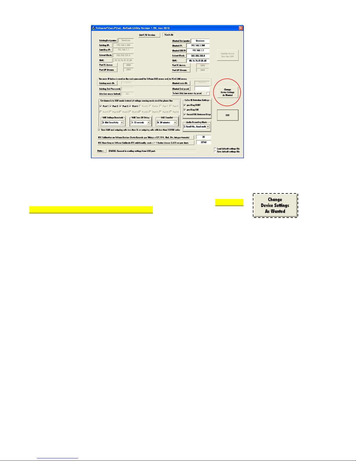
With the recorder connected to your PC via USB, open the TC Reflash Utility (V1.55). Note the
settings for RTC Calibration on TcVcom Devices and RTC Base Freq on TcVcom as shown in
the image below.
Calibration of the clock is accomplished by changing the numbers in the boxes shown as “0” and
“32768” in the above image. You must close TeleCorder software prior to using the Reflash Utility.
RTC Calibration on TcVcom Devices can be set to any number between 0 and 127. Each
increment will fine tune the RTC calibration slower by approximately ½ second per week. A lower number
will speed up the clock over a period of days and a higher number will slow down the clock.
RTC Base Freq on TcVcom can be set between 32665 and 32771. This is a course setting: each
increment changed to a lower number will force the clock to run faster by approximately 2.6 seconds per
day. Going to the next higher number will force the clock to run slower by approximately 2.6 seconds per
day. For example, changing two increments by going from 32768 to 32770 would cause the clock to run
about 5 seconds slower per day. Changing from 32768 to 32767 would cause the clock to run faster by
approximately 2.6 seconds per day. Calibration is periodic, not constant — check for improvement in RTC
accuracy after a few days. Checking after only a few hours will not provide accurate readings.
When finished, be sure to click on the Change Device Settings as Wanted
button. To lock the new settings into memory, power must be cycled (power the
recorder down by disconnecting power and re-connecting after a few seconds). Re-
sync time to the PC and confirm the improvement in accuracy after a few days.
Fine tune the calibration settings as necessary.

10 TeleCorder # TCwL-B4, V2.43, Revision 4, USA
NOTE: If the TeleCorder is connected to your network, the time can be set to synchronize with your PC
daily when the software is opened and at noon time and minimize the need to calibrate the RTC (see
Section 4.2).
3.6.8 Audio Recording Mode: From this sub-button you can set the quality of recordings.
Mode 0 --- Large file, good audio.
8bit linear PCM mode used in the 1st generation recorders.
Mode 1 --- Tiny file, poor audio.
2bit ADPCM mode.
Mode 2 --- Small file, good audio (default).
3bit ADPCM mode. Default mode set from factory.
Mode 3 --- Large file, best audio.
8bit nonlinear PCM mode.
3.6.9 Limitation for List Displaying: From this sub-button you can set the list display features to
speed up the list refresh process or to have more items displayed in the lists of recordings shown on your
PC in the main TeleCorder program screen. The default setting is 2000 for fastest speed. You can select a
different number, such as 10000, 32768 or 65536, respectively. This selection is saved in software, not as a
hardware setting and will be reset to 2000 every time the software is closed.
3.6.10 Caller ID Detection Settings: From this sub-button you can set (turn on/off) the caller ID
detection features.
Pre-Ring DTMF Detection: If the local caller ID mode is DTMF and sent before the ring, you
must turn this feature on. Otherwise, if erroneous caller numbers are
sometimes received, you should turn this feature off.
Pre-Ring FSK Detection: If the local caller ID mode is FSK and sent before the ring, you must
turn this feature on. Otherwise, if erroneous caller numbers are
sometimes received, you should turn this feature off.
Forced FSK Between Rings: If your caller ID signaling is FSK and sent between the rings, you
must turn this feature on. This is the normal setting for North America.
3.6.11 About TeleCorder PC S/W: From this sub-button, you can see additional information about
the TeleCorder software.
3.6.12 QUIT: Use this sub-button to exit the Hardware Information & Settings window.
3.6.13 Notes:
1. The above settings must be locked into the TeleCorder hardware by restarting the
recorder. After any of the above settings are changed, they will not take effect until the
recorder is restarted by turning off or disconnecting AC power to the TeleCorder, waiting
a minimum of ten seconds, and powering the TeleCorder back on. Any changes made in
software should now be locked into the recorder’s internal memory.
2. To avoid interruption of active recordings, you should only set the above items while the
recorder is idle. Wait until no channels are active or unplug inputs prior to changing settings.
3. After the settings have been changed, check to make sure that the recorder is functioning
as expected.
4. Therecorder listens for outgoing numbersdialed using DTMF/touch-tonesignalingand

TeleCorder # TCwL-B4, V2.43, Revision 4, USA 11
stores them with the recording. It is possible for it to document and record false phone
numbers when the recorder is in the VAR mode (particularly when recording broadcast radio
music where the audio can mimic sounds of dialing). To avoid collecting and recording these
erroneous numbers, you can use the PC interface to disable storing of dialed digit signaling.
4. Setup for Accessing the TeleCorder via LAN
After installing the TeleCorder by connecting it to your phone lines or other sources of conversation
audio and confirming that it is functioning properly, you are now ready to use the Reflash Utility via a
USB connection to setup access to the recorder from a network (LAN). Configure the IP address, Subnet,
and Default Gateway. Then select “change device settings” button, and restart the unit (power Off and ON
and unplug and reconnect the USB cable).
4.1 Reflash Utility Application to Find or Change IP Address
Connect the LAN cable to a network switch or to the LAN port on the back of your PC and then to the
LAN port on the TCwL-B4. Check to see that the cable connection indicator (RED) LED and activity
(GREEN) LED are lit on the back of the unit. Then proceed to run the Reflash Utility to find the recorder
on the LAN.
With the recorder connected to your network (LAN) or Ethernet port on a PC, open the TC Reflash
Utility that was installed onto your PC earlier (Section 2.5) to find the unit on the network. Initially the IP
address for TCwL-B4 is set as "192.168.1.200". If the IP segment of your network is within the same range
(“192.168.1.*”) it should be found by your PC. Be patient, this may take some time (many seconds). If
more than onerecorder is connected tothe same LAN, the IP addresses must be different.
NOTE: The utility will look for TeleCorder recorders connected via USB first and if no TeleCorder is
found on the PC USB ports, it will look for TeleCorder on the LAN. When connecting to recorders on the
LAN, you will need to disconnect any recorders connected to the PC via USB.
Select Find the Device Over the LAN. It will display the factory set
IP address on the screen when it is found by the Reflash Utility application.
12 TeleCorder # TCwL-B4, V2.43, Revision 4, USA
If the recorder cannot be found via the LAN, the IP address of the unit can be entered into the “Connect
Directly Using Wanted IP” box to search for the specific IP address. If your IP address range is within the
default range of the unit (192.168.1.200) you will not need the USB connection to access the TCwL-B4.
If the recorder cannot be found via the LAN, connect a USB cable between a PC and the back of the
recorder, then run the Reflash Utility (V1.55 or higher) and edit the device settings.
When finished, be sure to click on the Change Device Settings button. To lock the
new settings into memory, power must be cycled (power the recorder down and up).
When done, disconnect the USB and run the Reflash Utility again. When the
Reflash Utility finds the device, you are ready to run the TeleCorder software and access the recorder via
the LAN connection.
When the Reflash Utility (V1.55 or higher) is open and the device is found over the LAN, port settings
can be changed using the Reset by IP command. Find the device over the LAN, make your setting
changes, select the “Reset by IP” button then select the “Change Device Settings As Wanted” button.
Close the SW and reopen to verify changes.
4.1.1 Reflash Utility Application Notes (Version 1.55):
TCwL-B4 can be connected via USB or LAN. The utility will check for recorders from USB at boot
stage automatically (first). If no USB is detected, you can force it to search for the recorder over the LAN
via the Find the Device Over the LAN button. The device default IP will have to be within the same range
as the network for this to work.
The Direct IP input field for direct connection and setting can be used if the device is not found over the
LAN. Enter the IP and select find.
If you have a problem reading the device, you may check the right-bottom corner box to Load default
settings file (factory defaults).
When the device is successfully found, you can read the existing settings information from the device.
All these settings are copied into the Wanted settings fields.Edit these as necessary for your application.
.F/W Version: ex. FCwL4.05.
.Existing IP: ex. 192.168.1.200.
.Subnet Mask: ex. 255.255.255.0.
.Existing MAC: ex. 00.16.76.5F.8E.A5.
.Port TC Access: ex. 2008.
.Port UP Stream: ex. 2009.
.Handy Player Support: Yes (check mark for YES is default).

TeleCorder # TCwL-B4, V2.43, Revision 4, USA 13
.Existing Main ID & Wanted Main ID: This is the Master Password and is not available to view.
.Existing 2nd Password: The 2nd password created by the user can be used to unlock access to the
LAN as well as the Master Password (original recorder ID) if it is locked (password protected).
.LAN Access Locked: Yes/No. Select if the LAN access is password locked (protected).
When editing and testing settings is complete, you should check the box to Save default settings file to
save the default settings (as a template).
Make necessary changes for the logger’s line parameter settings (VAR modes etc.).
.Port 1-4: Checked if VAR mode is wanted, default is audio activation.
.VAR Voltage Threshold: Define the VAR sensitivity, Levels 1-4, default is mid sensitivity (2).
.VAR Turn Off Delay: Define time to wait for audio before turning off, levels 1-4, default is 12 sec.
.VAR Time Out: Define the Max length of call, Levels 1-4, default is 20 min. default (0).
.Caller ID Settings: All selected unless erratic characters result. USA standard is FSK.
.Audio Recording Mode: Recommended setting is the default, default is Small file good audio (2).
After editing, you can click the Change Device Settings As Wanted button to save the new settings
into the device.
NOTE: Be aware that the new settings will take effect after the device restart (power off and on).
The new settings will be saved in files named TCwLSettingsDefault.ept and TCwLSettingsUser.ept.
The files are saved to your PC. You may load these settings back into the logger as necessary.
It is very important to check all settings before restart.
Quit this application and launch again to check and verify your settings.
NOTE: Most settings can be changed via the USB or LAN connections once the unit is installed. You
can force the new settings remotely via the Reset by IP and then Change Device Settings as Wanted.
4.2 TeleCorder Settings that can only be accessed via LAN connection to PC
Most recorder settings and functions that can be setup via LAN are
the same as setting up and operating via USB (see manual Section 3).
When you open the TeleCorder software and it connects to the
recorder via LAN, the lower left corner of the software window will
show as with the image on the right instead as what shows when
connected via USB connection as shown in manual Section 5.1.2.
Clicking on the Settings For Auto Upload, Refresh, RTC button provides access to the functions only
available via LAN and will open the window shown below (see Section 5.1.27).

14 TeleCorder # TCwL-B4, V2.43, Revision 4, USA
Interval Settings for Refresh and/or Uploading: If you wish the list of recorded calls to automatically
refresh, select the interval here. Select either 1 minute, 5 minutes, 15 minutes, or 1 hour and
place a check in Enable periodic Auto-Refresh button. When connected via USB, every 1
minute is the only option. Leave all boxes unchecked if you do not wish the list to be
automatically refreshed (click Refresh on main window to refresh manually at any time).
The interval setting is also used to set the frequency for automatically uploading copies of
the recordings to the PC when it is connected to the recorder via LAN. Use the buttons to
Enable periodic Uploading as above setting, etc. to enable this feature and manage the file
type and where the recordings are stored on your PC.
Auto-sync device date/time to this PC once at every launch time and daily noon-time:
Activate this function if you wish to have the recorder automatically set its time/date to the PC.
If selected, the update will only take place when the software is open on your PC and it is
connected to the recorder.
5. Managing and Playing the Recordings
5.1 Managing and Playing Recordings with a PC
The TeleCorder requires a PC for setup and playing back recorded conversations. With a PC you will
also be able to convert recordings to standard wave files and archive them to storage on your PC. Playing
selected recordings from a PC will not inhibit recording.
The PC does not have to be ON or connected to the TeleCorder for it to function. Connecting the
TeleCorder USB cable to your PC and/or turning the PC power on or off will not stop the recorder from
functioning. You can also disconnect the TeleCorder USB cable from a PC and connect it to a different PC
without interrupting the TeleCorder operation.
5.1.1 Connection:
Connect the TeleCorder to the USB port in your PC using the provided USB cable. The PC used for
managing/playing must be equipped with an available USB port, sound card as well as speakers, and use
Windows® operating system Win-2000/XP/Vista/Win-7. If the recorder is connected to your network
(LAN), you can use supplied software and the LAN connection to access the recorder.
5.1.2 Using the Utility Software:
You must install the supplied utility TeleCorder Manager/Player software from the provided disk to
your computer prior to being able to manage the recorder from the PC or playing recordings through PC
control (see manual page 5, Section 2.3, Installing Software and Connecting to a PC). The first time
that you connect your PC to your TeleCorder, you may be asked to install the USB device driver. This
driver should have been copied to your PC during install. If not, use the CD supplied with your TeleCorder
to install the required USB driver following the instructions displayed on your computer.
After installing the software, place a short cut icon on the desktop for easy access (if it was
not automatically installed during install). Click the software icon or the short cut created during
the install and the recordings will be listed in the main window (as shown in the screen image on
the next page). The listed information includes the ITEM or sequential recording number, the PORT that
was the source of the recording, CALLER ID NUMBER (if available when the recording was made) or
DIALED NUMBER (if available when the recording was made), DATE and TIME the recording started,
and the DURATION of each recording in minutes and seconds. All records are listed in the reverse order so
that the most recent recording is indexed as item number 1.
You can drag the slider bar on the right side of the display window to view the un-displayed part of
the list. On the lower part of the form, there are buttons for Refresh, Re-Order, Find, Files, Info & Settings,
Security (Lock/Unlock), and Exit.

TeleCorder # TCwL-B4, V2.43, Revision 4, USA 15
The buttons provide the following functions:
5.1.3 Refresh: Refresh the list to display the latest recordings in the TeleCorder at any time.
There is also a check box for “Auto-Refresh every 1 minute” (see 4.2. if via LAN).
5.1.4 Re-Order: User can select one of the following ordering rules to re-order the list.
1. Recorded – provides a list based on the time recordings ended.
2. Start Time – provides a list based on the time recordings started.
3. Record Duration – provides a list based on the length of recordings.
4. Channel Number – provides a list based on the channel number.
5. Un-answered List – provides alist of calls on phone linesthatwere notanswered.
(Note: Unanswered Listing is not supported with TCwL-B4)
6. Quit – exits the re-order window.
5.1.5 Find: You can search the records using a specific port/channel number, caller number, dialed
number, and/or within a date and time range that you input.
In the dialogue box, you can enter search conditions such as date range, digits from a phone number
such as 010, 6256 etc. The searched results will display on the screen after you select “Start Search”.
You may also enter only a start and stop date range to display a list of recorded items that took place
during the date range you entered.
The recorded items, after a search, can be played or used for further searching and for making Wave
files in a batch job.

16 TeleCorder # TCwL-B4, V2.43, Revision 4, USA
5.1.6 Files: This button provides the following functions for the displayed files. Click “File range” for
access to a select range of files that are to be saved to PC.
5.1.7 Conversion of Recordings to WAVE or .UPx (TeleCorder) Files and Saving to PC
Wave Files are a widely used and supported multimedia File Format for the PC and other computer
systems. Since the TeleCorder uses a unique format for saving the recordings in digital form, digitally
converting them is a better way to exchange information with other systems that do not have TeleCorder
software. You can use your PC to send audio recordings via e-mails or make backup CDs without worrying
that others may not be able to play them. .UPx files are stored in the TeleCorder format.
There is an option to save individual recordings when they are selected for playback (select the
button with red dot “Q” from playback menu). Use the Browse button to select the folder on your PC hard
drive where you wish to save the copies of the recordings.
These buttons provide the following functions:
zAll — Copy all of the records listed in the form, including both the ones displayed and the
ones not displayed. This button would be used to copy all recordings retrieved by a search.
zLast Month — The software will search again from all of the records in the TeleCorder
within the 1st and 31st of last month, then perform a batch job to generate the wave files. This
function is specially designed for users to make monthly backups.
zLast Week —The software will search again from all of the records in the TeleCorder
within the last week, and then it will do a batch job to generate the wave files.
zHelp — Producesawindow with more detailedinformation about converting to wavefiles.
zUse exclusive fast mode if possible — Use this button to speed up thefile conversion.
zFile Range — Use this button to
select a range of files that will be converted
to wave files from the list of calls. For
example, files numbered between 1 and 100. Select RangeGo button to see details on file
conversion and save process prior to selecting OK to start the process.
All the generated files will be placed in the file folder you select in the window left of the
Browse button. After the files have been converted and saved to your PC, the list of calls on the

TeleCorder # TCwL-B4, V2.43, Revision 4, USA 17
TeleCorder Recording List will show only those files and needs to be refreshed to show all calls.
Each file refers to a unique record. The name of each file contains date and time of the call,
caller or dialed number such as File P2 10-26-10 09=11=10 DIAL TO 18609280377.WAV
(recording made on TeleCorder Port 2on October 26th, 2010 at 09:11:10, call was outgoing and
dialed to 1-860-928-0377). The files are suffixed with “.Wav”. You can change the file names as
required, but you should not change the suffix unless there are special requirements.
Volume Balance Setting (DAVA): Digital Automatic Volume Adjustment capabilities. This is
done in software, not hardware. If the volume levels of the 2 sides of a conversation are different,
or if the line quality is not well adjusted, the Digital Automatic Volume Adjustment (DAVA)
function will amplify the lower or far side to more closely match the level of the stronger or near
side of a recorded conversation during playback. Since background noise will also be amplified
together with the sound, there will be a compromise to permit weak voices to be played at higher
levels without raising background noise levels to objectionable levels. There are 2 possible
settings:
USE DAVA (auto volume adjustment) for Volume Balance: This setting is normally used
to enable DAVA when converting single files or batches of files to wave
files. It provides a medium amount of boost for weak audio.
DEEPER DAVA Mode (may have more noise): This setting provides a higher level of boost
to weak audio but may also increase weak background noise levels.
5.1.8 Print and Save the List of Records: The displayed list on the screen can be printed or saved
into a “.txt” file. No matter how the call list is re-ordered, the searched and sorted list can be printed.
5.1.9 Delete Recordings: The recorded calls can be selectively orentirely deleted.To avoid
unauthorized deletion, the password must be entered before deleting recordings. If no password has been
set, you will need the master password that was supplied with your TeleCorder. Options are to delete the
most recent recording, all recordings, or a selected range of recordings. Unanswered is not supported with
TCwL-B4 recorders.
From Delete Item(s) box click on Select Range button and follow screen messages to select which
recordings you wish to delete from the recorder’s hard drive. After selecting which recordings to delete,
you will be provided with an option to “Confirm: Files are deleted as desired?”. Follow on screen
instructions to recover the recordings as needed. If file recovery is selected, recovery will take place when
the TeleCorder software is closed and re-opened. Recordings made after selecting recovery and re-opening
the software will be permanently lost.
5.1.10 Hardware: From the Info & Settings button you can access all of the recorder’s hardware and
information settings:

18 TeleCorder # TCwL-B4, V2.43, Revision 4, USA
5.1.11 Hardware Information: From thissub-buttonyouwill gain information about the TeleCorder
including version number, capacity, media’s usage, recorded call items, deleted call items, etc.
5.1.12 Date/Time Setting: Fromthis sub-buttonyou can read and set the real time clock in therecorder.
5.1.13 Set Channels to VAR Mode Instead of Voltage Sensing Mode used for Recording from
Phone Lines: Each channel (Port) in the recorder can be set to start and stop recording using either audio
activation (VAR) or voltage sensing. Channels showing a check mark in the boxes labeled Port 1, Port 2,
Port 3, or Port 4, are set for VAR recording. Channels with no checkmark indicate they are set for phone
line recording. For any channel you want to start/stop recording using the phone line voltage sensing mode,
click on the box for that channel to remove the check mark, then click the Write Hardware button to
confirm any changes.
5.1.14 VAR Voltage Threshold: Set the threshold level to match the audio level on your audio source.
L0: Extra Sensitive, suitable for weak audio sources with low background noise level: (for
example, with weak earphone or line-out recording).
L1: High Sensitivity, suitable for normal line level audio sources with low background noise
levels: (normal phone handset earpiece audio or weak speaker of radio).
L2: Mid Sensitivity, suitable for higher than normal audio levels and/or higher background noise
levels: (for recording from a noisy phone line when voltage sensing cannot be used due to non-
standard voltages or with normal speaker audio from a radio).
L3: Low Sensitivity, suitable for very high audio levels, and high background noise levels.
Recording may stop if audio levels are too weak: (phone recording with non-standard and very
noisy DC voltages, or extra loud radio audio).
After making changes, click the button labeled Write Hardware to confirm any changes. You may
be asked to quit the program and try again. You may also need to unplug and re-connect the TeleCorder
power to successfully change the TeleCorder operating parameters.
5.1.15 VAR Turn Off Delay: If any channels have VAR selected for recording start/stop, select one of
the turn off delay options (VAR Turn Off Delay): 4, 12, 32 or 100 seconds. This setting will help to prevent
recordings from ending during quiet periods. Click the Write Hardware button to confirm any changes.
5.1.16 VAR Time Out: If any channels have VAR selected for start/stop, set the timeout to one of the
four choices: 20, 40, 60 or 80 minutes. This setting will limit the maximum length of a recording for easier
management of long conversations or for when recording from broadcast radio where pauses may not be
long enough to separate individual recordings using VAR for start/stop. If a recording reaches the maximum
length of time that you select for VAR Time Out, that recording will end and a new recording on that
channel will begin. Click the Write Hardware button to confirm any changes.
5.1.17 Save VAR and Outgoing Calls Less than 8s or Outgoing Calls with Less than 3 DTMF
Codes: Click on this option to place a check mark in its box if you want to save recordings that are less
than 8 seconds long. If this box is not checked, VAR recordings shorter than 8 seconds, and outgoing
telephone calls (using voltage sensing for start/stop) with less than 3 DTMF digits, will not be saved.
This setting is normally used if external noise causes frequent and unwanted false audio activated
recordings,or if telephone line testing produces short off-hookconditionsthat are not associated with actual
phone line usage. It is normal torecord all activity on the monitored circuits.Usecare when setting to delete
short recordings.
5.1.18 Audio Recording Mode: From this sub-button you can read or set the quality of recordings.
Mode 0 --- Large file, Good audio.
8bit linear PCM mode, 28.80 MB/hour
Mode 1 --- Tiny file, Poor audio.
2bit ADPCM mode, 7.20 MB/hour
Mode 2 --- Small file, Good audio.
3bit ADPCM mode. Default mode set from factory, 10.84 MB/hour
Mode 3 --- Large file, Best audio.
8bit nonlinear PCM mode, 28.80 MB/hour

TeleCorder # TCwL-B4, V2.43, Revision 4, USA 19
5.1.19 Limitation for List Displaying: From this sub-button, you can select the number of
recordings that will be listed on the PC to speed up the list refresh process. The default setting is 2,000.
This setting will cause your PC to display the most recent 2,000 recordings after a refresh. You can select a
different number, such as 10,000, 32,768 or 65,536. This selection is saved in software, not as a hardware
setting and will reset to 2,000 if the software is closed and reopened.
5.1.20 Caller ID Detection Settings: From this sub-button you can set (turn on/off) the caller ID
detection features.
Pre-Ring DTMF Detection: If the local caller ID mode is DTMF and sent before the ring,
you must turn this feature on. Otherwise, if erroneous caller numbers are
sometimes received, you should turn this feature off.
Pre-Ring FSK Detection: If the local caller ID mode is FSK and sent before the ring, you
must turn this feature on. Otherwise, if erroneous caller numbers are
sometimes received, you should turn this feature off.
Forced FSK Between Rings:If your caller ID signaling is FSK and sent between the
rings, you must turn this feature on. This is the normal setting for North
America.
5.1.21 About TeleCorder PC Software: From this sub-button, you can view information
about the software supplied with the TCwL-B4 recorders.
5.1.22 QUIT: From this sub-button, you can Quit or Exit the Hardware Info & Settings window.
5.1.23 Lock/Unlock: This button provides access to security settings for the recorder.
Lock: After the recorder is locked, it will ask the user to input a password each time a
user tries to access the recorder. A password must be entered to use this function.
Unlock: To unlock the recorder so that a password is not needed, the password
must be entered.
5.1.24 Modify Password: The recorder comes with a factory-set password, which is in the machine
code that is set by its hardware and cannot be changed. This password is written on a sheet that comes
with the recorder and will be an effective password forever (keep this password in a secure place). The
TeleCorder also allows you to set a second password that can be easier to remember. Use the Modify
Password button to set asecond password of 6-8 characters. You must enter the factory-set password prior
to being given the opportunity to add a second password. After the second password has been set, it will
have the same effect as the first password. The new password is also stored in the hardware of the recorder
so that it will work even if the recorder is connected to, and used with, another PC. Use Unlock to disable
the second password.
5.1.25 USB Password:
Locking the Unit from Access via the USB Only: Open the TeleCorder SW and select the
SECURITY button at the bottom of the screen. You will have option buttons for LOCK, UNLOCK,
and MODIFY PASSWORD (PC). To lock the unit from USB access only using the supplied MASTER
PASSWORD, select the LOCK button and enter the supplied Master Password when prompted. The
unit is now locked and will require the Master Password when the SW is opened.
Other manuals for TCwL-B4
1
Table of contents
Other TeleCorder Voice Recorder manuals


