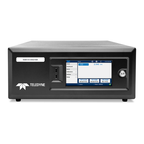
083730100 DCN8060 Teledyne API T100 SO2Analyzer with NumaView™ Software xi
Figure 2-24. Pneumatics with Zero/Span Valves Option ............................................................................ 47
Figure 2-25. Pneumatics with Ambient Zero/Pressurized Span Valves Option.......................................... 48
Figure 2-26. Pneumatics with IZS Option ................................................................................................... 49
Figure 2-27. Pneumatics with O2Sensor.................................................................................................... 50
Figure 2-28. Status Screens at Startup....................................................................................................... 51
Figure 2-29. Home Page Example.............................................................................................................. 51
Figure 2-30. Viewing Active Alerts Page..................................................................................................... 52
Figure 2-31. Sample Dashboard Page ....................................................................................................... 53
Figure 2-32. User Interface Orientation ...................................................................................................... 55
Figure 2-33. Concentration and Stability Graph (top) and Meter Graph (bottom) ...................................... 56
Figure 2-34. Dashboard Page..................................................................................................................... 57
Figure 2-35. Navigating to the Active Alerts Page ...................................................................................... 58
Figure 2-36. Active Alerts Cleared .............................................................................................................. 59
Figure 2-37. Utilities>Alerts Log of Active and Past Alerts and Events ...................................................... 59
Figure 2-38. Datalog Configuration, New Log Page ................................................................................... 61
Figure 2-39. Datalog Configuration, Existing Log ....................................................................................... 61
Figure 2-40. Creating a New Data Log ....................................................................................................... 62
Figure 2-41. Datalog Periodic Trigger Configuration .................................................................................. 63
Figure 2-42. Datalog - Conditional Trigger Configuration ........................................................................... 64
Figure 2-43. DAS Download Page.............................................................................................................. 64
Figure 2-44. Events List .............................................................................................................................. 65
Figure 2-45. Event Configuration ................................................................................................................ 65
Figure 2-46. Configured Event Sample....................................................................................................... 66
Figure 2-47. Edit or Delete an Event........................................................................................................... 66
Figure 2-48. Dashboard Display and Configuration.................................................................................... 67
Figure 2-49. Homescreen Configuration..................................................................................................... 69
Figure 2-50. Digital Outputs Setup.............................................................................................................. 70
Figure 2-51. Analog Output Configuration Example ................................................................................... 71
Figure 2-52. Analog Outputs Group Calibration Screen ............................................................................. 72
Figure 2-53. Analog Outputs Manual Calibration Screen (AOUT2 Example)............................................. 72
Figure 2-54. Setup for Checking / Calibrating DCV Analog Output Signal Levels ..................................... 73
Figure 2-55. Setup for Checking / Calibration Current Output Signal Levels ............................................. 74
Figure 2-56. Alternative Setup Using 250Ω Resistor for Checking Current Output Signal Levels ............. 75
Figure 2-57. Communications Configuration, Network Settings ................................................................. 77
Figure 2-58. Configuration Transfer............................................................................................................ 78
Figure 3-1. MODBUS via Ethernet.............................................................................................................. 82
Figure 3-2. MODBUS via Serial Communication (example)....................................................................... 83
Figure 3-3. Serial Communication, Setting Hessen Protocol...................................................................... 84
Figure 3-4. Hessen Gas List Configuration................................................................................................. 87
Figure 4-1. Setup for Manual Calibration without Z/S Valve or IZS Option ................................................ 93
Figure 4-2. Multi-Point Calibration Page..................................................................................................... 94
Figure 4-3. Setup for Manual Calibration Check with Z/S Valve or IZS Option .......................................... 95
Figure 4-4. Zero and Span Calibration Screens ......................................................................................... 96
Figure 4-5. Auto Cal Page........................................................................................................................... 97
Figure 5-1. Report Generation Page......................................................................................................... 104
Figure 5-2. Remote Update Page ............................................................................................................. 105
Figure 5-3. Manual Update Page (and other utilities) ............................................................................... 105
Figure 5-4. Touchscreen Calibration Page ............................................................................................... 106
Figure 5-5. Time Zone Change Requirements ......................................................................................... 107
Figure 5-6. Replacing the Particulate Filter............................................................................................... 108
Figure 5-7. Critical Flow Orifice Assembly................................................................................................ 111
Figure 5-8. Critical Flow Orifice Assembly................................................................................................ 112
Figure 5-9. Flow Calibration Menu............................................................................................................ 116
Figure 5-10. Simple Leak Check Fixture................................................................................................... 117
Figure 5-11. Hydrocarbon Scrubber Leak Check Setup........................................................................... 117


