I610 GB PL 07 19 31100447
1
WARNING!
– Carefully read the manual before the installation or use.
– This equipment is to be installed by qualified personnel, complying to current standards, to avoid damages or safety
hazards.
– Remove eventual dangerous voltage from the product before any maintenance operation on it.
– The manufacturer cannot be held responsible for electrical safety in case of improper use of the equipment.
– Products illustrated herein are subject to alteration and changes without prior notice. Technical data and descriptions in
the documentation are accurate, to the best of our knowledge, but no liabilities for errors, omissions or contingencies
arising therefrom are accepted.
– A circuit breaker must be included in the electrical installation of the building. It must be installed close by the equipment
and within easy reach of the operator.
It must be marked as the disconnecting device of the equipment: IEC /EN 61010-1 § 6.11.
– Fit the instrument in an enclosure or cabinet with minimum IP51 degree protection.
– Clean the instrument with a soft dry cloth, do not use abrasives, liquid detergents or solvents.
INTRODUCTION
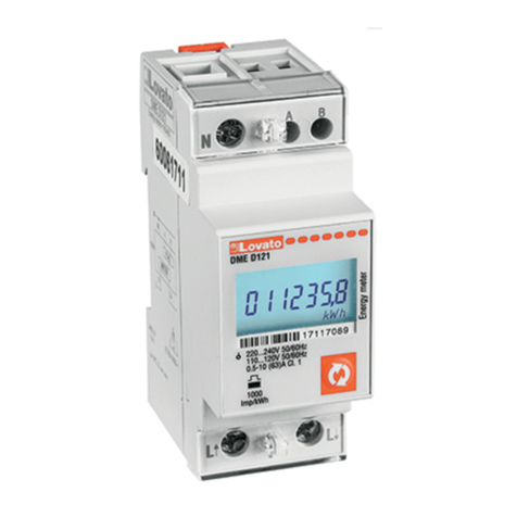
The DME D111 is a single-phase active and reactive energy meter for direct connection, for currents up to 40A, equipped with
a built-in RS485 serial interface.
The energy accuracy is compliant with standard IEC/EN 62053-21 class 1.
Apart from energy metering, it can measure additional indications, for a total of 14 measurements that can be visualized on
the LCD display.
The DME D111 has a standard 1U (18mm wide) modular housing and is supplied with sealable terminal blocks.
DESCRIPTION
– Modular DIN-rail housing, 1U (18mm wide).
– Direct connection for currents up to 40A.
– Active energy measure complies IEC/EN 62053-21 class 1.
– Counter with 5+1 digits.
– Button for measure selection and programming.
– Total active and reactive energy meters.
– Partial active and reactive energy meters, resettable.
– Hour counter, total and partial.
– Pulse LED for active energy consumption.
– Indication of instantaneous consumption (active power).
– RS485 interface with Modbus-RTU and ASCII protocols.
SELECTION OF READINGS
– Pressing briefly the button it is possible to select the readings on the display, following the sequence in the table
reported below.
– Each measure is indicated by the correspondent icon in the higher part of the display.
– After one minute has elapsed after the last keystroke, the display moves automatically back to the total active energy
screen.
UWAGA!!
– Przed użyciem i instalacją urządzenia należy uważnie przeczytać niniejszą instrukcję.
– W celu uniknięcia obrażeń osób lub uszkodzenia mienia tego typu urządzenia muszą być instalowane przez
wykwalifikowany personel, zgodnie z obowiązującymi przepisami.
– Przed rozpoczęciem jakichkolwiek prac na urządzeniu należy odłączyć napięcie od wejść pomiarowych.
– Producent nie przyjmuje na siebie odpowiedzialności za bezpieczeństwo elektryczne w przypadku niewłaściwego
użytkowania urządzenia.
– Produkty opisane w niniejszym dokumencie mogą być w każdej chwili udoskonalone lub zmodyfikowane. Opisy oraz
dane katalogowe nie mogą mieć w związku z tym żadnej wartości umownej.
– W instalacji elektrycznej budynku należy uwzględnić przełącznik lub wyłącznik automatyczny. Powinien on znajdować
się w bliskim sąsiedztwie urządzenia i być łatwo osiągalny przez operatora. Musi być oznaczony jako urządzenie służące
do wyłączania urządzenia: IEC/ EN 61010-1 § 6.11.
– Montować urządzenie w obudowie o stopniu ochrony (minimalnym) IP51.
– Urządzenie czyścić miękką szmatką, nie stosować środków ściernych, płynnych detergentów lub rozpuszczalników.
WPROWADZENIE
DMED111 jest jednofazowym licznikiem energii do podłączenia bezpośredniego do 40A, wyposażonym w interfejs RS485.
Pomiar energii jest zgodny z normą IEC/EN 62053-21 klasa 1.
Oprócz pomiaru energii jest w stanie dostarczyć dalszych informacji, łącznie 14 pomiarów, które można wyświetlić na dużym
wyświetlaczu LCD.
DMED111 ma standardową obudowę modułową o szerokości 1U (18 mm) i jest standardowo dostarczany z plombowanymi
osłonami zacisków.
OPIS
– Wykonanie modułowe, szerokość obudowy 1U (18mm) do montażu na szynie DIN.
– Podłączenie bezpośrednie do 40A.
– Pomiar energii czynnej zgodny z IEC/EN 62053-21, klasa 1.
– Licznik: 5 cyfr + 1.
– Przycisk wyboru pomiarów i programowania.
– Całkowite liczniki energii czynnej i biernej.
– Liczniki energii częściowej z możliwością kasowania.
– Liczniki całkowite i częściowe.
– Dioda sygnalizująca zużycie energii czynnej.
– Wskazanie zużycia chwilowego (moc czynna).
– Interfejs RS485 z protokołami Modbus-RTU i ASCII.
WYBÓR POMIARÓW
– Po krótkim naciśnięciu przycisków na wyświetlaczu urządzenia można wybrać pomiary zgodnie z kolejnością
przedstawioną w poniższej tabeli.
– Każdemu wyborowi odpowiada ikona w górnej części wyświetlacza.
– Po jednej minucie bez naciskania przycisku pomiar przenosi się na licznik całkowity energii czynnej.
Icon Measurement Format
kWh Total active energy 00000,0
kWh + Part Partial active energy 00000,0
kvarh Total reactive energy 00000,0
kvarh + Part Partial reactive energy 00000,0
V Voltage 000,0
A Current 00,00
kW Active power 00,00
kvar Reactive power 00,00
PF Power factor 0,00
Hz Frequency 00,0
h
➊
Hour counter (hhhhh.mm) 0000,00
h + Part
➊
Partial hour counter (hhhhh.mm) 0000,00
kW +d
❷
Average active power (15 min demand) 00,00
kW+d+▲
❷
Max avg. active power (max demand) 00,00
Ikona Pomiar Format
kWh Całkowita energia czynna 00000,0
kWh + Part Częściowa energia czynna 00000,0
kvarh Całkowita energia bierna 00000,0
kvarh + Part Częściowa energia bierna 00000,0
V Napięcie 000,0
A Prąd 00,00
kW Moc czynna 00,00
kvar Moc bierna 00,00
PF Współczynnik mocy 0,00
Hz Częstotliwość 00,0
h
➊
Licznik (hhhhh.mm) 0000,00
h + Part
➊
Licznik częściowy (hhhhh.mm) 0000,00
kW +d
❷
Średnia moc czynna (zapotrzebowanie z 15 min) 00,00
kW+ d +▲
❷
Maks. średnia moc czynna (maksymalne zapotrzebowanie) 00,00
➊
These measurements are shown only enabling parameter P-08.
❷
These measurements are shown only enabling parameter P-09.
➊
Pomiary te widoczne są po włączeniu parametru P-08.
❷
Pomiary te widoczne są po włączeniu parametru P-09.
DME D111
GB
JEDNOFAZOWY LICZNIK ENERGII, PODŁĄCZENIE BEZPOŚREDNIE Z PORTEM RS485
Instrukcja techniczna
PL
LOVATO ELECTRIC S.P.A.
24020 GORLE (BERGAMO) ITALIA
VIA DON E. MAZZA, 12
TEL. 035 4282111
E-mail info@LovatoElectric.com
Web www.LovatoElectric.com
SINGLE-PHASE DIRECT CONNECTION ENERGY METER WITH RS485 INTERFACE
Installation manual
METROLOGICAL LED
– The red LED on the front emits 1000 pulses for every kWh of consumed Energy (that is, one pulse every Wh).
– The pulsing frequency of the LED gives an immediate indication of the energy flowing in every moment.
– The pulse duration, LED colour and intensity are compliant with the reference standards that define its utilization in order
to verify the accuracy of the energy meter.
RS485 INTERFACE
– Via the RS485 interface the value of energy meters and can be read from DME D111 as well as all other measures.
– The device acts as a standard Modbus slave.
– The configuration of the serial communication is done with the setup parameters from P-20 to P-24.
– The map of the measures on the Modbus protocol is shown in the following Modbus address table chapter.
For a more detailed description, see technical instruction I315 (downloadable from website www.LovatoElectric.com).
– For wiring diagrams, see the end of this manual.
PROGRAMMABLE LIMIT THRESHOLD
– Through parameters from P-02 to P-07 it is possible to define the behaviour of a programmable limit threshold, whose
status can be read from the communication protocol (see modbus addresses table).
– The programmable limit threshold can be used for instance to signal alarm situation to a remote device.
– Note: during parameter setting (setup) the status of the programmable limit threshold is not updated.
INCORRECT WIRING INDICATION
– In case of incorrect wiring, when the device detects a reverse energy flow, the display shows the blinking code Error 3.
– This error is caused by either reverse connection of current wires (terminals L↑and L↓) or reverse voltage wiring
(terminals N - L↑).
– In these conditions, the energy is not counted.
WSKAŹNIK METROLOGICZNY LED
– Czerwona dioda przednia emituje 1000 impulsów na każdą kWh zużywanej lub oddawanej energii (czyli 1 impuls
na każdą Wh).
– Częstotliwość migania diody daje natychmiastowe wskazanie przepływu energii w danym momencie.
– Czas migania, kolor i intensywność diody są zgodne z normami, które określają jej wykorzystanie do celów
metrologicznej kontroli dokładności licznika.
INTERFEJS RS485
– Poprzez interfejs RS485 możliwy jest odczyt z DMED111 zarówno wartości liczników energii jak i innych pomiarów.
– Urządzenie pracuje jako Slave w standardzie Modbus.
– Ustawienia parametrów komunikacji dokonuje się w parametrach P-20 do P-24.
– Mapa protokołów Modbus podana została w tabeli adresów Modbus.
Bardziej szczegółowy opis znajduje się w instrukcji technicznej I315
(do pobrania ze strony www.LovatoElectric.com).
– Schematy połączeń znajdują się na końcu niniejszej instrukcji.
PROGRAMOWALNE PROGI LIMITÓW
– Pzy użyciu parametrów od P-02 do P-07 można zdefiniować zachowanie programowalnego progu limitu, którego stan
można odczytać za pomocą protokołu komunikacyjnego (patrz tabela adresów Modbus).
– Programowalny próg limitu może być używany na przykład do sygnalizacji zdalnej alarmów.
– Uwaga: podczas ustwień parametrów status programowalnego progu limitu nie jest aktualizowany.
WSKAZANIA BŁĘDU PODŁĄCZENIA
– W przypadku nieprawidłowego podłączenia, gdy urządzenie wykryje przepływ energii w przeciwnym kierunku, aktywuje
się migające wskazanie Error 3.
– Ten błąd może być spowodowany odwrotnym podłączeniem pomiaru prądu (zaciski L ↑i L ↓) lub odwrotnym
podłączeniem pomiaru napięcia (zaciski N - L↑).
– W tym przypadku energia nie jest zliczana.


