Samoa NEXU Operating manual

1
R. 06/21 838 861
SAMOA Industrial, S.A. · Pol. Ind. Porceyo, I-14 · Camino del Fontán, 831 · 33392 - Gijón - Spain · Tel.: +34 985 381 488 · www.samoaindustrial.com
2021_06_11-10:00
Part No. / Cód. / Art. Nr.:
NEXU FLUID
MANAGEMENT SYSTEM
Parts and technical service guide
Guía de servicio técnico y recambios
Service- und Ersatzteilhandbuch
NEXU INSTALLATION MANUAL 2
MANUAL INSTALACIÓN NEXU 58
NEXU INSTALLATIONSHANDBUCH 114
EN
ES
DE

2838 861 R. 06/21
SAMOA Industrial, S.A. · Pol. Ind. Porceyo, I-14 · Camino del Fontán, 831 · 33392 - Gijón - Spain · Tel.: +34 985 381 488 · www.samoaindustrial.com
2021_06_11-10:00
EN
1. HOW TO USE THIS MANUAL .......................................................................................................................... 4
2. COMPONENTS PRESENTATION..................................................................................................................... 4
2.1 KEYPADS (UDAT, UDAT POWER+)............................................................................................................................... 4
2.2 ADDITIONAL POWER SUPPLY (UPOWER, UPOWER+) ............................................................................................. 4
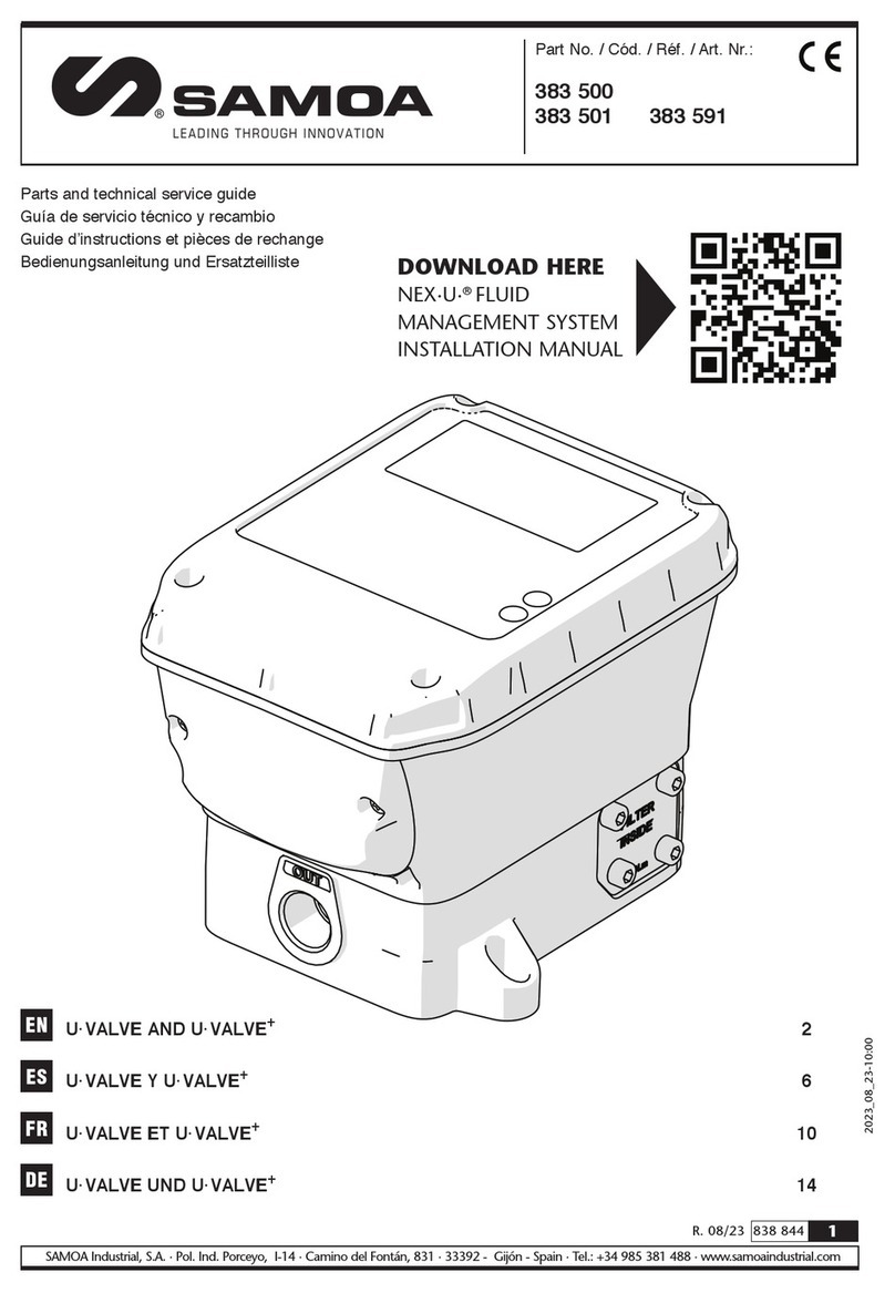
2.3 FLOW CONTROL UNIT (UVALVE)................................................................................................................................. 4
2.4 FLOW DISPENSE MANAGEMENT (UCOUNT)............................................................................................................. 5
2.5 REMOTE DISPLAY UNIT (UVIEW) ................................................................................................................................ 5
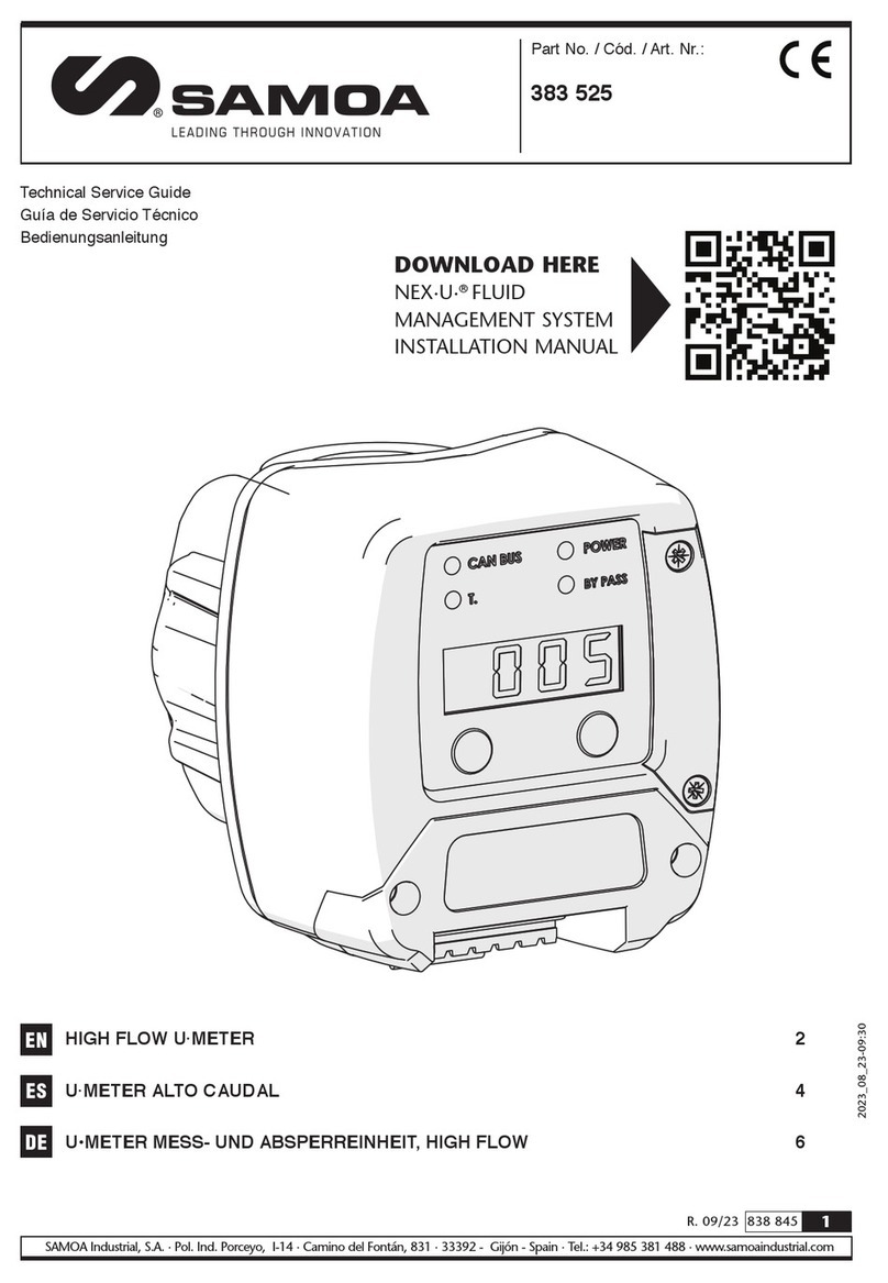
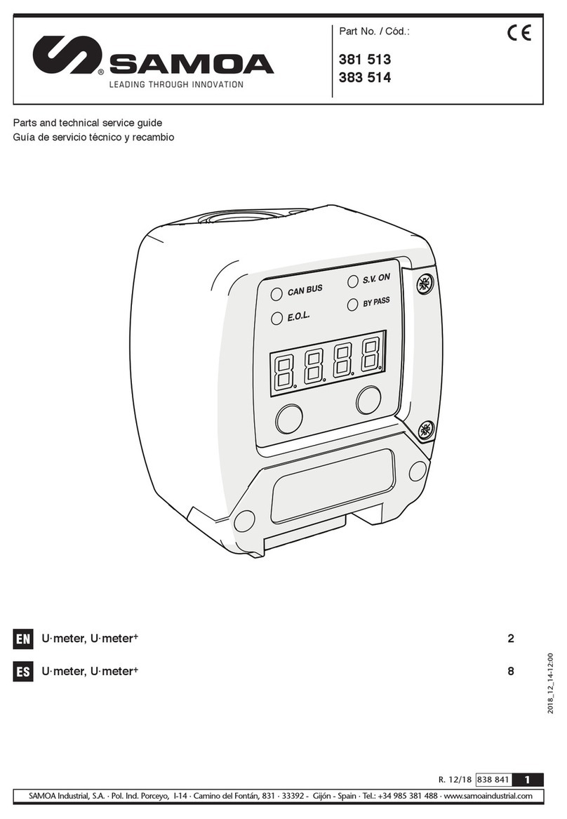
2.6 INTELIGENT COMPACT PULSE METER (UMETER, UMETER+)................................................................................ 5
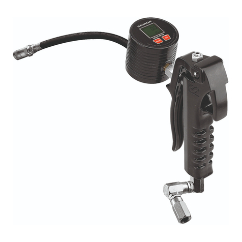
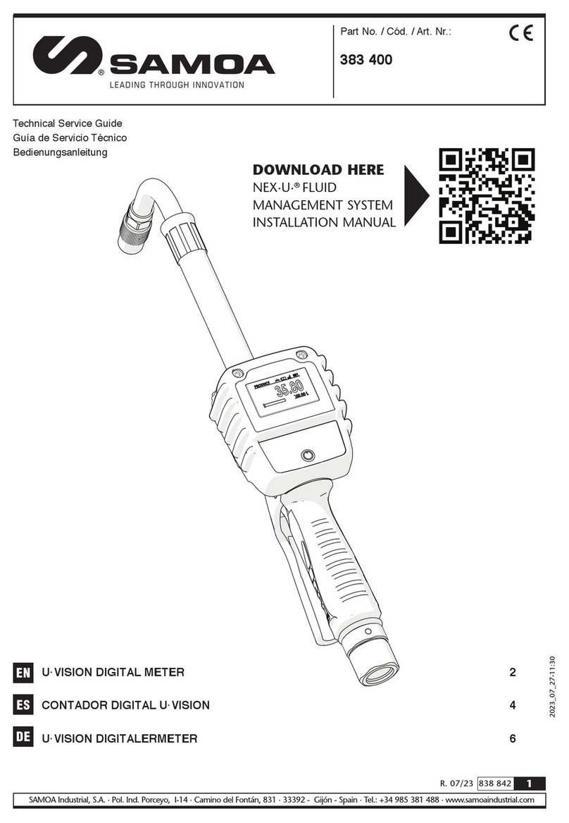
2.7 HAND HELD DISPLAY (UVISION, UVISION+) .............................................................................................................. 5
2.8 LINE PULSE METER (UPULSER, UPULSER+)............................................................................................................ 6
2.9 TANK LEVEL MONITOR MODULE (UTANK)................................................................................................................. 6
2.10 CENTRAL PROCESSING UNIT (UNET)...................................................................................................................... 6
2.11 CODED KEYS SET (CK5) ............................................................................................................................................ 6
2.12 FLOW CONTROL UNIT (UCF-24V) ............................................................................................................................. 7
2.13 FLOW CONTROL UNIT FOR WINDSCREEN LIQUID (UCFL-24V) ............................................................................ 7
2.14 VOLUMETRIC PROBE (VP-4M) .................................................................................................................................. 7
2.15 ADJUSTABLE LEVEL CONTACT PROBE ................................................................................................................... 7
2.16 FLASH LIGHT INDICATOR (ATS-FLASH) ................................................................................................................... 7
2.17 BAR CODE READER (LCB)......................................................................................................................................... 7
3. INSTALLATION AND CABLING ....................................................................................................................... 8
3.1 NETWORK TOPOLOGY................................................................................................................................................. 8
3.1.1 WIRED INSTALLATION.................................................................................................................................................... 8
3.1.2 WIRELESS INSTALLATION.............................................................................................................................................. 9
3.1.3 HYBRID INSTALLATION ................................................................................................................................................ 10
3.2 LOCATION OF THE CONNECTION POINTS / INDICATING LEDS .............................................................................11
3.2.1 UDAT / UDAT POWER+............................................................................................................................................................. 11
3.2.2 UPOWER / UPOWER+ ............................................................................................................................................................... 13
3.2.3 UVALVE / UVALVE+................................................................................................................................................................... 13
3.2.4 UCOUNT .................................................................................................................................................................................... 14
3.2.5 UVIEW ........................................................................................................................................................................................ 15
3.2.6 UMETER / UMETER+ ................................................................................................................................................................. 16
3.2.7 UVISION / UVISION+ ................................................................................................................................................................. 16
3.2.8 UPULSER / UPULSER+.............................................................................................................................................................. 16
3.2.9 UTANK ....................................................................................................................................................................................... 17
3.2.9.1 STAND BY DISPLAY .......................................................................................................................................................... 19
3.2.10 UNET........................................................................................................................................................................................ 20
3.3 FIXING OF THE ELEMENTS ....................................................................................................................................... 21
3.3.1 UDAT / UDAT POWER+................................................................................................................................................. 21
3.3.2 UPOWER / UPOWER+ ................................................................................................................................................... 21
3.3.3 UVALVE / UPULSER / UPULSER+................................................................................................................................. 21
3.3.4 UCOUNT / UVIEW.......................................................................................................................................................... 22
3.3.5 UMETER / UMETER+ ..................................................................................................................................................... 22
3.3.6 UVISION / UVISION+ ..................................................................................................................................................... 22
3.3.7 UTANK ........................................................................................................................................................................... 23
3.4 NETWORK CABLING................................................................................................................................................... 23
3.4.1 CABLING FROM UDAT / UDAT POWER+ TO UVALVE................................................................................................. 24
3.4.2 CABLING UVALVE / UMETER / UMETER+ TO UVALVE / UMETER / UMETER+ .......................................................... 24
3.4.3 CABLING FROM UDAT / UDAT POWER+ TO UDAT / UDAT POWER+........................................................................ 24
3.4.4 CABLING FROM UDAT / UDAT POWER+ TO UVALVE (UMETER / UMETER+) TO UDAT / UDAT POWER+
(ONLY FOR TWO CONNECTORS UDATS) .................................................................................................................... 25
3.4.5 CABLING FROM UNET TO UDAT / UDAT+................................................................................................................... 25
3.4.6 CABLING FROM UTANK TO UDAT / UDAT+................................................................................................................ 26
3.4.7 CABLING FROM UTANK TO UVALVE / UMETER / UMETER+...................................................................................... 26
3.4.8 POWER SUPPLY CONNECTION ................................................................................................................................... 26
4. SETTING PROCEDURE AND DEFINITION OF THE PARAMETERS ........................................................... 27
4.1 SETTING PROCEDURE .............................................................................................................................................. 27
4.2 ADDRESS DEFINITION ............................................................................................................................................... 27
4.3 END OF LINE (EOL) RESISTORS (FOR TWO-CONNECTOR UDATS) ..................................................................... 27
INDEX

3
R. 06/21 838 861
SAMOA Industrial, S.A. · Pol. Ind. Porceyo, I-14 · Camino del Fontán, 831 · 33392 - Gijón - Spain · Tel.: +34 985 381 488 · www.samoaindustrial.com
2021_06_11-10:00
EN
INDEX
4.4 END OF LINE (EOL) RESISTORS (FOR THREE-CONNECTOR UDATS)................................................................. 27
4.5 LOCAL PARAMETERS SETUP.................................................................................................................................... 28
4.5.1 LOCAL PARAMETERS SETUP ON A UVALVE / UVALVE +........................................................................................... 28
4.5.2 LOCAL PARAMETERS SETUP ON A UMETER / UMETER+.......................................................................................... 29
4.5.3 LOCAL PARAMETERS SETUP ON UDAT / UDAT POWER+ ......................................................................................... 30
4.5.4 LOCAL PARAMETERS SETUP ON UCOUNT ................................................................................................................ 31
4.5.5 LOCAL PARAMETERS SETUP ON UVIEW .................................................................................................................... 31
4.5.6 LOCAL PARAMETERS SETUP ON UVISION ................................................................................................................. 31
4.5.7 LOCAL PARAMETERS SETUP ON UVISION+............................................................................................................... 32
4.5.8 LOCAL PARAMETERS SETUP ON UTANK.................................................................................................................... 33
4.5.9 LOCAL PARAMETERS SETUP ON UNET ...................................................................................................................... 33
4.6 DIAGNOSIS OF THE NETWORK STATUS.................................................................................................................. 33
5. NEXU REQUIREMENTS ................................................................................................................................. 34
6. SOFTWARE CONFIGURATION...................................................................................................................... 34
6.1 INSTALLATION PROCESS .......................................................................................................................................... 34
6.1.1 HOW TO CHANGE THE IPV4 ADDRESS FOR A LOCAL NETWORK............................................................................ 34
6.2 CONFIGURATION PROCESS ..................................................................................................................................... 35
6.2.1 PRODUCTS.................................................................................................................................................................... 36
6.2.2 DEVICES ........................................................................................................................................................................ 37
6.2.2.1 UTANK.................................................................................................................................................................... 38
6.2.2.2 TANK ...................................................................................................................................................................... 38
6.2.2.3 UDAT...................................................................................................................................................................... 38
6.2.2.4 UVALVE / UVALVE+............................................................................................................................................... 39
6.2.2.5 UMETER / UMETER+ ............................................................................................................................................. 39
6.2.2.6 UCOUNT ................................................................................................................................................................ 40
6.2.2.7 UVIEW .................................................................................................................................................................... 40
6.2.2.8 UVISION ................................................................................................................................................................. 40
6.2.2.9 UVISION+............................................................................................................................................................... 40
6.2.2.10 AIR SV .................................................................................................................................................................. 40
6.2.2.11 MOBILE UNIT....................................................................................................................................................... 40
6.2.2.12 LUBE TRUCK ....................................................................................................................................................... 41
6.2.3 GROUPS ........................................................................................................................................................................ 42
6.2.4 DISPENSE SCRIPT......................................................................................................................................................... 42
6.2.5 ERP / DMS...................................................................................................................................................................... 43
6.2.6 SEND.............................................................................................................................................................................. 43
6.2.7 SYSTEM TOOLS............................................................................................................................................................. 43
6.2.8 NETWORK...................................................................................................................................................................... 44
7. MANAGER ...................................................................................................................................................... 44
7.1 HOME ........................................................................................................................................................................... 44
7.2 TRANSACTIONS.......................................................................................................................................................... 45
7.3 TANKS / MOBILE UNITS / TANK TRUCKS................................................................................................................. 47
7.3.1 TANKS............................................................................................................................................................................ 47
7.3.2 MOBILE UNITS............................................................................................................................................................... 48
7.3.3 TANK TRUCKS............................................................................................................................................................... 48
7.4 USERS.......................................................................................................................................................................... 49
7.5 EVENTS........................................................................................................................................................................ 50
7.6 DEVICES ...................................................................................................................................................................... 50
7.6.1 DISPENSE POINT........................................................................................................................................................... 50
7.6.2 UDAT.............................................................................................................................................................................. 52
7.6.3 UTANK ........................................................................................................................................................................... 52
7.6.4 UVISION+....................................................................................................................................................................... 52
7.6.5 AIR SV ............................................................................................................................................................................ 53
7.6.6 MOBILE UNIT................................................................................................................................................................. 53
7.6.7 LUBE TRUCK ................................................................................................................................................................. 53
8. QUICK PANEL................................................................................................................................................. 54
9. VIRTUAL TERMINAL...................................................................................................................................... 54
10. UDAT OPERATION ......................................................................................................................................... 55
11. UVISION+ OPERATION.................................................................................................................................. 55
12. HOSE REEL CALIBRATION........................................................................................................................... 56
4838 861 R. 06/21
SAMOA Industrial, S.A. · Pol. Ind. Porceyo, I-14 · Camino del Fontán, 831 · 33392 - Gijón - Spain · Tel.: +34 985 381 488 · www.samoaindustrial.com
2021_06_11-10:00
EN
This manual is divided into 12 chapters. Please read all of them before making the installation and configuration of the NexU.
• Chapter 2: describes all the elements of the system.
• Chapter 3: describes how fix and wire all the elements.
• Chapter 4 describes the setting procedure and the local parameters definition.
• Chapter 5 describes the requirements for connecting the NexU to the customer network.
• Chapter 6 defines how to make the configuration of the installation in the UTrack.
• Chapter 7 and 8: describe the menus for the person or persons who will be in charge of controlling the UTrack (NexU software).
• Chapter 9 to 11: describes the menu for the user (person or persons who will supply fluid).
• Chapter 12: describes how to calibrate hose reels.
NOTE: Chapters 7 to 12 are NOT part of the configuration process.
2.1. KEYPADS (UDAT, UDAT POWER+)
2.2. ADDITIONAL POWER SUPPLY (UPOWER, UPOWER+)
1. HOW TO USE THIS MANUAL
2. COMPONENTS PRESENTATION
This unit is one of the interfaces user / system through the keypad and
the display.
There are two versions for this unit:
• Udat Power+ which can open up to 8 solenoid valves.
(Max. output power 320 W).
• Udat which can open up to 2 solenoid valves.
(Max. output power 75 W)
The power supply is to be 115 VAC or 230 VAC – 50 Hz.
UPower connects using CAN bus cable to a UValve, UValve+, UMeter,
UMeter+, UCount or UView whenever the power supplied by a UDat
keypad is not present.
There are two versions for this unit:
• UPower+ which can open up to 8 solenoid valves.
(Max. output power 320 W).
• UPower which can open up to 2 solenoid valves.
(Max. output power 75 W).
The power supply is to be 115 VAC or 230 VAC – 50 Hz.
Nexu is made up of the following components:
2.3. FLOW CONTROL UNIT (UVALVE)
This flow control unit is composed by:
• A solenoid valve.
• A pulser (328 pulses per litre).
• A filter.
• An electronic board that controls part of the dispense procedure.
It includes an integrated display that can show the hose reel number
(in stand-by state) and the delivered quantity (when dispensing).
• A Bluetooth module that connects the device to a UVision.
It can be linked to the system via CANBUS or Wi-Fi®. The connection
threads are F1/2” (inlet and outlet). Compatible with oil and cooling.

5
R. 06/21 838 861
SAMOA Industrial, S.A. · Pol. Ind. Porceyo, I-14 · Camino del Fontán, 831 · 33392 - Gijón - Spain · Tel.: +34 985 381 488 · www.samoaindustrial.com
2021_06_11-10:00
EN
2. COMPONENTS PRESENTATION
2.4. FLOW DISPENSE MANAGEMENT (UCOUNT)
2.5. REMOTE DISPLAY UNIT (UVIEW)
2.6. INTELIGENT COMPACT PULSE METER
(UMETER, UMETER+)
2.7. HAND HELD DISPLAY (UVISION, UVISION+)
It is used for controlling an external flow control unit (24VDC solenoid
valve and pulser). It can be considered as the electronic part of an UValve
and, therefore, it has got a display that works in the same way as
in the UValve.
It can be linked to the system via CANBUS or Wi-Fi®.
It has a Bluetooth module that connects the device to a UVision.
It shows the dispensed quantity when a transaction through certain
UValve / UCount is taking place.
It is used to have a second indication (apart from the one in the
UValve / UCount display)
A UView can show the quantity dispensed by several UValve / UCount
(not simultaneously).
This compact pulse meter unit is composed by:
• A pulser.
• An electronic board that controls part of the dispense procedure.
• It includes an integrated display that can show the hose reel
number (in stand-by state) and the delivered quantity
(when dispensing).
• Additionally, a Bluetooth module can be installed to the device to
be linked to a UVision.
This module is a Hand-held display module to fit a SAMOA oil control
handle.
Includes a backlight display connected via Bluetooth®with a UValve,
UMeter+ or UCount module.
The UVision has a screen that repeats the measurement that is shown in
the previous devices
The UVision+ can do the same as the UVision and it has an access keypad
that allows introducing work orders.

6838 861 R. 06/21
SAMOA Industrial, S.A. · Pol. Ind. Porceyo, I-14 · Camino del Fontán, 831 · 33392 - Gijón - Spain · Tel.: +34 985 381 488 · www.samoaindustrial.com
2021_06_11-10:00
EN
2.8. LINE PULSE METER (UPULSER, UPULSER+)
2.9. TANK LEVEL MONITOR MODULE (UTANK)
2.10. CENTRAL PROCESSING UNIT (UNET)
2.11. CODED KEYS SET (CK5)
The UPulser+ is a high accuracy line pulse meter module combined with
a 24 V solenoid valve and an inlet filter screen. Reduces installation time
and eliminates the risk of leaks when using separate components.
Equipped with fast connection in/out CAN bus terminals. It can only be
connected to a UCount module. This meter does not have a display or
function buttons.
The UPulser is a high accuracy line pulse meter. It is equipped with
connection terminal and valve open indication light. It can only be
connected to a UCount module. This meter does not have a display or
function buttons a display or function buttons and requires a 24 V DC
solenoid valve.
This module is capable of controlling two tanks. When mounted in a
NEX·U·®system it keeps real time inventory and increases operation
safety preventing air entering pumps when the tank is empty and
overflow during clean oil delivery and in waste oil storage tanks. It can
also be used to control the general air supply to the pumps and the air
supply for each pump.
The UTank has two independent graphic displays and level bars, each of
them shows the inventory available in each tank. It also has a set-up
keypad for inventory adjustment if required.
The UNet is the key NEX·U·® component. It is the central processing unit
that controls the system communications and houses the UTrack
software. This has to be connected to the customer computer network.
The UNet includes a powerful 2.4 GHz processor and 4 GB RAM. It
controls the system functions and it manages the wired and wireless
communication between the NEX·U·® components.
It has two CAN bus ports (in/out) for wired communications and an
ethernet port that allows UNet to connect to an existing Wi-Fi® network
or to create a dedicated Wi-Fi® network
Coded key with a secret ID for quick identification on the coded key
reader on UDat and UDat power+.
2. COMPONENTS PRESENTATION

7
R. 06/21 838 861
SAMOA Industrial, S.A. · Pol. Ind. Porceyo, I-14 · Camino del Fontán, 831 · 33392 - Gijón - Spain · Tel.: +34 985 381 488 · www.samoaindustrial.com
2021_06_11-10:00
EN
2.12. CODED KEYS SET (CK5)
This flow control unit is composed by:
• A solenoid valve.
• A pulser.
• A filter.
The connection to the piping is F1/2” (inlet and outlet).
Compatible with oil and cooling.
It has to be controlled by a UCount.
2. COMPONENTS PRESENTATION
2.13. FLOW CONTROL UNIT FOR WINDSCREEN LIQUID
(UCFL-24V)
2.14. VOLUMETRIC PROBE (VP-4M)
2.15. ADJUSTABLE LEVEL CONTACT PROBE
2.16. FLASH LIGHT INDICATOR (ATS-FLASH)
2.17. BAR CODE READER (LCB)
This flow control unit is composed by:
• A solenoid valve.
• A pulser (328 pulses per litre).
• A filter.
The connection to the piping is F1/2”G (inlet and outlet).
Compatible with windscreen liquid.
It has to be controlled by a UCount.
Piezoelectric probe for controlling real stock on a tank:
• Maximum height: 4 meters
• Pressure setting: 400 mBar
• It has to be controlled by a UTank.
Please check liquid compatibility before using.
• Adjustable lenght contact probe
• Lenght: 5.0 meter
• Tank connection: M2”G
• It has to be controlled by a UTank.
Coded key with a secret ID for quick identification on the coded key
reader on UDat and UDat power+.
Bar code reader to be connected to a UDat.
For use with bar code work orders or bar coded ID users.

8838 861 R. 06/21
SAMOA Industrial, S.A. · Pol. Ind. Porceyo, I-14 · Camino del Fontán, 831 · 33392 - Gijón - Spain · Tel.: +34 985 381 488 · www.samoaindustrial.com
2021_06_11-10:00
EN 3. INSTALLATION AND CABLING
3.1 NETWORK TOPOLOGY
3.1.1 WIRED INSTALLATION
NexU allows three different configurations:
• Wired: In the standard case we have only one line common to all the units of the system. In this line you have to connect all the elements of
the system following the CANBUS philosophy.
• Wireless: In the standard case, communication is made via WiFi. The only wiring you have to connect is for power supply
• Hybrid: A mix of the two previous ones.
As a general rule, one power supply can supply a maximum of 8 units for UDat power+ or UPower+ and a maximum of 2 units
for UDat or UPower.
For two-connectors UDat (See paragraph 3.2.1), a clear example of how to lay a wired installation can be seen in this figure:
You see that there are two different colours for the same wiring. Magenta colour represents communication and power and red colour represents
only communication. It means that the right UDat powers up four elements at the right and the left UDat powers up four elements at the left.
Yellow wiring represents the customer computer network.

9
R. 06/21 838 861
SAMOA Industrial, S.A. · Pol. Ind. Porceyo, I-14 · Camino del Fontán, 831 · 33392 - Gijón - Spain · Tel.: +34 985 381 488 · www.samoaindustrial.com
2021_06_11-10:00
EN
3. INSTALLATION AND CABLING
In this case, you see only magenta wiring. This wiring carries power and communication.
Yellow wiring represents the customer computer network.
For Samoa cabling red and black wires are used for power and white, blue and screen are used for data.
NOTE: Although wiring colors could be used in another way, it is highly recommended to follow this rule.
For three-connectors UDat (See paragraph 3.2.1), a clear example of how to lay a wired installation can be seen in this figure:
3.1.2 WIreless
In this case the UNet is connected to a Wi-Fi Router (Samoa Supply) and it connects (and transfers information) to a UDat. This UDat powers up and
transfers information to the rest of the elements.

10 838 861 R. 06/21
SAMOA Industrial, S.A. · Pol. Ind. Porceyo, I-14 · Camino del Fontán, 831 · 33392 - Gijón - Spain · Tel.: +34 985 381 488 · www.samoaindustrial.com
2021_06_11-10:00
EN 3. INSTALLATION AND CABLING
3.1.3 HYBRID INSTALLATION
In this case, you can see a mix between wired installation and wireless installation (between the UValve and the Wi-Fi Router (Samoa Supply).
In all the cases, Wi-Fi and wired communication is made by Samoa but, as NexU is connected to the customer computer network, UTrack can be
accessed via any PC/Tablet/Mobile which is in the network (either wired or Wi-Fi).

11
R. 06/21 838 861
SAMOA Industrial, S.A. · Pol. Ind. Porceyo, I-14 · Camino del Fontán, 831 · 33392 - Gijón - Spain · Tel.: +34 985 381 488 · www.samoaindustrial.com
2021_06_11-10:00
EN
3. INSTALLATION AND CABLING
3.2. LOCATION OF THE CONNECTION POINTS / INDICATING LEDS
3.2.1 UDAT / UDAT Power+
For two-connectors UDat and UDat Power+, we can find this board:
1. By-pass key switch: It bypasses the units which are powered up by the UDat.
2. BUS OUT Quick Connector: It transfers power and communication to the network. Wiring from this BUS OUT connector has to be linked to
BUS IN connector if connected to another UDat / UDat Power+
3. BUS IN Quick Connector: It transfers communication (not power) to the network. Wiring from this BUS IN connector has to be linked to BUS
OUT connector if connected to another UDat / UDat Power+
IMPORTANT: In the last two cases (2 and 3), if the items to be connected need to be powered up, then all the wires (BLACK/RED/SCREEN/WHITE/
BLUE) must be connected and it must be done only in the BUS OUT connector. If they only need to be connected for communications then only
SCREEN/WHITE/BLUE have to be connected (no matter if it is made in BUS IN or BUS OUT connector).
4. RS232 Port: Allows peripheral devices connections. Mainly for service.
5. USB Port: Allows peripheral devices connections. Mainly for service and updating.
6. iButton Reader: Allows identification via iButton® key.
7. Power Connector: IEC Power Socket for 240 VAC or 110 VAC, 50 / 60 Hz. Wiring for this connector must be 3 x 1.5 mm2 minimum.
8. RFID reader: Allows identification via RFID card.
42
7
31 5 6
8
For three-connectors UDat and UDat Power +, we can find this board:

12 838 861 R. 06/21
SAMOA Industrial, S.A. · Pol. Ind. Porceyo, I-14 · Camino del Fontán, 831 · 33392 - Gijón - Spain · Tel.: +34 985 381 488 · www.samoaindustrial.com
2021_06_11-10:00
EN 3. INSTALLATION AND CABLING
You will see there is another connector (orange colour) and the philosophy is a little bit different and it implies different wiring.
Now BUS IN and BUS OUT are only used for transferring communication and GROUP is used for transferring power and communication to the
elements which are connected to that connector. As a guidance, the wire that is connected to GROUP is the one that is marked with a red arrow.
Wiring for UDat and UDat+ is as follow.
Be aware that this is the standard way of connecting.
Please check chapter 3.4 for particular wiring.
For two-connectors UDat and UDat Power +, we can find this board:
For thee-connectors UDat and UDat Power +, we can find this board:
Be aware that this is the standard way of connecting.
Please check chapter 3.4 for particular wiring.

13
R. 06/21 838 861
SAMOA Industrial, S.A. · Pol. Ind. Porceyo, I-14 · Camino del Fontán, 831 · 33392 - Gijón - Spain · Tel.: +34 985 381 488 · www.samoaindustrial.com
2021_06_11-10:00
EN
3. INSTALLATION AND CABLING
3.2.2 UPOWER / UPOWER+
3.2.3 UVALVE / UVALVE+
There are three terminals the ones that have to be used are the ones at
both sides. They are IN and OUT.
The one in the middle will be used for further features.
There are two terminals (IN and OUT).
Regarding LEDS and buttons you can find: Adress indication
Delivered quantity
Solenoid opening
indication
Bypass indication
Online CANBUS indication
End of Line indication
Configuration buttons

14 838 861 R. 06/21
SAMOA Industrial, S.A. · Pol. Ind. Porceyo, I-14 · Camino del Fontán, 831 · 33392 - Gijón - Spain · Tel.: +34 985 381 488 · www.samoaindustrial.com
2021_06_11-10:00
EN
3.2.4 UCOUNT
3. INSTALLATION AND CABLING
The device has 3 screen display modes, named “standby mode,
“standard” mode and “XXL” mode.
The “standby” mode (figure 1) is the display mode shown when no
transaction is in progress. While a transaction is being made, the screen
will show the “standard” mode (figure 2) or the “XXL” (figure 3)
according to the device configuration (see the “menu configuration”
section for more details).
Depending on the screen mode, the unit address (1), the fluid volume
dispensed (2), the progress status bar of the transaction (3) or the
indicator which shows that the solenoid valve is open (4),
will be displayed.
Connect the COM terminal of the pulse meter to the COM terminal (5) of the UCount electronic board. Connect the pulse generator terminal of the
pulser to terminal “A” (9) of the UCount. If the pulser has a double reed switch connect the other pulse generator terminal of the pulser to terminal
“B” (7) of UCount electronic board.
Regarding LEDS and buttons you can find:
• 1 - Address indication / Delivered quantity
• 2 and 3 - Configuration buttons
• 4 - Indication LEDS. From left to right Solenoid opening
indication, bypass indication, online CANBUS indication,
End of Line indication.
As per the UValve, there are two terminals (IN and OUT) for the CANBUS.
For connecting the UCount with external flow control unit (24VDC solenoid valve and pulser), you need to use the A B COM SV OUT1 terminals.
Fig. 1 Fig. 3
1 2
Fig. 2
3 2
14
95
7
321 4

15
R. 06/21 838 861
SAMOA Industrial, S.A. · Pol. Ind. Porceyo, I-14 · Camino del Fontán, 831 · 33392 - Gijón - Spain · Tel.: +34 985 381 488 · www.samoaindustrial.com
2021_06_11-10:00
EN
3.2.5 UVIEW
3. INSTALLATION AND CABLING
As per the UValve, there are two terminals (IN and OUT) for the CANBUS.
The device has 3 screen display modes, named “standby mode,
“standard” mode and “XXL” mode.
The “standby” mode (figure 1) is the display mode shown when no
transaction is in progress. While a transaction is being made, the screen
will show the “standard” mode (figure 2) or the “XXL” (figure 3)
according to the device configuration (see the “menu configuration”
section for more details).
Depending on the screen mode, the unit address (1), the fluid volume
dispensed (2), the progress status bar of the transaction (3) or the
indicator which shows that the solenoid valve is open (4), will be
displayed.
Regarding LEDS and buttons you can find:
• 1 - Address indication / Delivered quantity
• 2 and 3 - Configuration buttons
• 4 - Indication LEDS. From left to right Solenoid opening
indication, bypass indication, online CANBUS indication,
End of Line indication.
95
7
321 4
fig. 1 fig. 3
1 2
fig. 2
3 2
14

16 838 861 R. 06/21
SAMOA Industrial, S.A. · Pol. Ind. Porceyo, I-14 · Camino del Fontán, 831 · 33392 - Gijón - Spain · Tel.: +34 985 381 488 · www.samoaindustrial.com
2021_06_11-10:00
EN
BLUE
WHITE
MESH
RED
BLACK
3.2.6 UMETER / UMETER+
Plug in the 2 pole male connector (6) in the 2 pole female connector (7)
of the unit.
Connect each wire of the CAN BUS cable to the 5 pole male plug
according to the scheme.
NOTE: Depending on installation layout, it may be possible that in one
of the 5 pole plugs, the power wires (red/black) must be left unconnected.
Plug in the 5 pole connector (8) in either of the 5 pole female connectors
of the unit. In case that only one male connector is connected, use the
bottom female socket. Plug into the upper female socket of the unit the
protection cap (11).
In order to install the Bluetooth kit (if not already installed from factory),
follow the next steps:
• Turn off and disconnect the power source of the unit.
• Remove the plastic cover (1) unscrewing the screws (2).
• Insert the wireless PCB kit (3) in the socket as it is shown. Pay
attention to PCB orientation.
• Mount the new provided cover (4) with the two screws (2).
• Turn on and/or connect again the unit power source.
• At this point, the unit is already prepared to be paired with a
U-Vision or U-Vision+ unit.
All the items will be explained in the Local Parameters chapter.
• Regarding buttons F1 and F2, apart from being used for configuration,
they give more information.
• Press and hold F1 button to show the installed firmware version in
the display.
• Press and hold F2 button to show the power supply voltage
(in volts).
3. INSTALLATION AND CABLING
3.2.7 UVISION / UVISION+
These units have to be connected to a UCount module.
UPulser has a double channel reed switch. A (6) represents the first pulse
generator and B (8) represents the second pulse generator. COM (4) is
the common wire.
Regarding LED indications and buttons, UPulser label indicates the
meaning of each one.
UPulser+ has no buttons and it has to be connected as per the picture.
3.2.8 UPULSER / UPULSER+
6
69
8
7
11
12
3
4
2
6 4
8

17
R. 06/21 838 861
SAMOA Industrial, S.A. · Pol. Ind. Porceyo, I-14 · Camino del Fontán, 831 · 33392 - Gijón - Spain · Tel.: +34 985 381 488 · www.samoaindustrial.com
2021_06_11-10:00
EN
3. INSTALLATION AND CABLING
These are the main external elements of the UTank:
1. RGB LED graphic bars.
2. 128x64 backlight LCD display.
3. Keypad.
4. Status LEDs .
5. Bypass key switch.
This unit needs external mains power. You have to connect the PSU unit
to 240 VAC / 110 VAC 50 / 60 Hz mains supply. Wiring for this connector
must be 3 x 1.5 mm2minimum.
This unit can control up to two tanks with different kind of probes
(analogue or contact probes) and the communication has to be made via
CANBUS and it can control a general air supply solenoid valve and one
air solenoid valve for each pump.
3.2.9 UTANK
In the attached drawing, Channel 1 indicates the connectors for the
Tank 1 and Channel 2 indicates the connectors for the Tank 2
J21 and J22 connectors are both meant to connect the U-TANK unit to
the NEX-U CAN-BUS network.
No power lines (black/red wires) are required for the operation of this unit.
Connect each wire of the CAN-BUS cable to the 5 pole male plug
(951982) according to the scheme shown.
This unit can control up to 2 fluid tanks, each of them will be connected
into one channel of the unit. Both channels are symmetrical and has the
same functionality (inputs/outputs). If only one tank is connected to the
unit, it must be assigned to channel 1.
For each channel, these are the available inputs/outputs. The following
picture is for channel 1; channel 2 is identical:
1
1
4
3
2
5
POWER CONNECTION

18 838 861 R. 06/21
SAMOA Industrial, S.A. · Pol. Ind. Porceyo, I-14 · Camino del Fontán, 831 · 33392 - Gijón - Spain · Tel.: +34 985 381 488 · www.samoaindustrial.com
2021_06_11-10:00
EN
These three inputs allow connecting up to three contact probes (float
type or equivalent).
Each input has a different logic meaning:
S1 – IN 1 (SIGNAL): changes the stock level indicated in both the
display and the graph bar.
S2 – IN 2 (WARNING): triggers the warning level into the system and
turns into yellow colour the graph bar.
S3 – IN 3 (STOP): triggers the stop level into the system, turns into red
colour the graph bar and gives power to the External Alarm Input.
Also, it is possible to use only one or two contact probes: if only one probe
is used, it must be connected to S3 (STOP) input; if only two probes are
used, they must be connected to S2 (WARNING) and S3 (STOP).
NOTE: Analogue and contact probes cannot be used simultaneously into
the same tank.
This input allows connecting an analogue level probe in order to get in
real time an exact measurement of the fluid level inside the tank.
Currently, only barometric level probes Samoa code 382120)
are supported.
The probe must be connected as follows (red to +24V, black to IN, shield
to GND; leaving +12V disconnected).
This input allows connecting a safety contact probe (float type or
equivalent). Only normally-closed (NC, the electrical contact inside the
probe must stay closed when the fluid level is below the probe) switch-
type probes can be used.
This input, together with the overfill valve output, is meant as a safety
device to prevent overfilling the tank. By setting the overfill probe at the
maximum allowed fluid level inside the tank (full tank level), it stops the
fluid from entering the tank as soon as the overfill level probe is reached.
NOTE: this input/output is independent from the system, does not
require any setup, and will not trigger any warning into the system. In
can be used together with both analogue and contact probes.
OUTPUT LOGIC:
• Active (24VDC OUT) when the fluid reaches the overfill probe
• Inactive (0VDC OUT) when the fluid is below the contact probe.
This output allows controlling the compressed air supply to the pump
associated with this tank: when there is an active transaction that requires
fluid from the tank, the pump is supplied with compressed air in order to
make it work; and when there is no active transaction requiring fluid from
this tank, the pump does not get any compressed air supply and,
therefore, is depressurized.
This helps to minimize compressed air leaks and reduces the physical
stress of the pump.
NOTE: Analogue and contact probes cannot be used simultaneously into
the same tank.
Contact probe inputs (Signal / Warning / Stop)
Note that the three probes must be set at different heights depending on
the type of tank being monitored (fresh fluid tank or waste fluid tank):
Overfill input/output Pump control output
3. INSTALLATION AND CABLING
Fresh fluid
tank Waste fluid
tank
S1 S3
S2 S2
S3 S1

19
R. 06/21 838 861
SAMOA Industrial, S.A. · Pol. Ind. Porceyo, I-14 · Camino del Fontán, 831 · 33392 - Gijón - Spain · Tel.: +34 985 381 488 · www.samoaindustrial.com
2021_06_11-10:00
EN
Active (24VDC OUT) while one or more FCU units (U-Valve, U-Meter,
U-Count) physically connected to the tank are performing a transaction,
and at the same time, the level is not below Stop contact level (S3) or
while the unit is in bypass mode.
Inactive (0VDC OUT) when there is no transaction in any of the
aforementioned units.
This output is intended to control an external (remote) flash indicator
and/or warning buzzer. It is controlled by the system’s warning and stop
levels (regardless of the type of probes being used): if the warning level
of stop level is triggered for this tank, this output becomes active.
OUTPUT LOGIC:
• Active (24VDC OUT) when the fluid reaches either the warning or
stop level
• Inactive (0VDC OUT) when the fluid is above (for fresh fluid tank) or
beyond (for waste fluid tank) the warning level.
Active (0VDC OUT) when the fluid is below the contact probe.
Inactive (24VDC OUT) when the fluid is in touch with the Stop contact
level (S3).
This output is intended to control the general air supply into the
workshop. A time schedule can be set into the U-Track software with the
working periods during which the air supply must be available.
Alternatively, this output can be controlled manually from the U-Track
(without time schedule).
OUTPUT LOGIC:
• Active (24VDC OUT) when the general air status is set to ON
(according to the time schedule or by setting it manually), or while
the unit is in bypass mode
• Inactive (0VDC OUT) when the general air status is set to OFF.
Fresh product
External alarm output
Waste oil
General air supply solenoid valve
3. INSTALLATION AND CABLING
When the unit is in standby mode (the switch key is in “normal”
position), the following screen will appear like this.
Several items provide the user with information about the system’s status:
The arrow above each tank indicates whether it is a fresh fluid tank (arrow
pointing upwards) or a waste fluid tank (arrow pointing downwards).
The symbol at the right side of each tank indicates that the setup
information for the tank has been successfully received from the
U-Track software.
The symbol at the right side of each tank indicates that an analogue
probe is currently connected to the analogue input of the tank. If this
probe is sending an acceptable value, the symbol is also displayed.
If the tank has been set to use digital probes, up to three indications (S1,
S2, S3) will appear at the left side of the tank, indicating which digital
probes have been enabled. Note that the order of the probes changes
depending on whether it is a fresh fluid tank (Stop probe/S3 will be at
the bottom of the tank) or a waste fluid tank (Stop probe/S3 will be at
the top of the tank).
The volume of fluid inside the tank is displayed in real time above each
tank, expressed in the units of the system (L for litres, G for gallons). If
the tank is using analogue probes, this quantity is the exact volume
measured by the unit; if the tank is using digital probes, this quantity is
the volume estimated by the U-Track.
3.2.9.1 STAND BY DISPLAY
Below each tank, the tank number inside the system is displayed (1 to
52), along with the status of the pump control output:
• READY: pump is depressurized and ready for delivering fluid.
• RUNNING: pump is pressurized and delivering fluid to one or more
dispensing points.
• STOP: pump is depressurized and is locked from delivering fluid
because either the tank is empty (fresh fluid tank) or the tank is full
(waste fluid tank).
Also, the fluid level is displayed graphically inside the tank, and through
the associated LED graph bar, and will change accordingly with the
measured level.
Note that the lighting colour of the graph bar segments will change
depending on the status of the tank: if the tank is in “normal” status, the
lighting colour will be green; if the tank is beyond “warning” level, the
lighting colour will be yellow; and if the tank is beyond “stop” level, the
lighting colour will be red.

20 838 861 R. 06/21
SAMOA Industrial, S.A. · Pol. Ind. Porceyo, I-14 · Camino del Fontán, 831 · 33392 - Gijón - Spain · Tel.: +34 985 381 488 · www.samoaindustrial.com
2021_06_11-10:00
EN
1. Ethernet terminal. To be connected to the customer computer
network or Samoa Wi-Fi router
2/3. USB ports (4 units). In one of them you will find a USB dongle in
which a backup is made periodically.
4. CAN Bus connections.
5. End of Line switch.
1. Power input. This is a 5 VDC input but the UNet has got a transformer
to convert mains power (110 VAC or 240 VAC) to 5 VDC
2. HDMI connector. Only for service.
3. Micro USB connector. Only for service.
The wiring has to be made as shown in the picture.
If two CANBUS connections have to be made, then connect the upper
terminal in the same way. In this case, the EOL resistor has to be
deactivated (see local parameters chapter)
Regarding LED indications and buttons, UNet label indicates the meaning
of each one.
1. Reset button.
In the event of restarting the UNet, it has to be pressed.
2. Status Indicator.
Power: It indicates if there is power to the unit.
Status: It indicates if CANBUS is OK.
Onine: It indicates if it is ready for working.
RX: Communication Flow to the unit.
TX: Communication Flow from the unit.
Rear View
Side View
3.2.10 UNET
3. INSTALLATION AND CABLING
32 54
1
3
2
1
12
Other manuals for NEXU
1
Table of contents
Languages:
Other Samoa Measuring Instrument manuals

Samoa
Samoa 411100 User manual

Samoa
Samoa 383 700 How to use

Samoa
Samoa 383 401 Operating manual

Samoa
Samoa U-VISION 383 400 How to use

Samoa
Samoa U-VISION 383 400 Operating manual

Samoa
Samoa 415000 How to use

Samoa
Samoa MP30 Operating manual

Samoa
Samoa U-METER User manual

Samoa
Samoa Oval Gear Meter User manual

Samoa
Samoa 365601 Operating manual