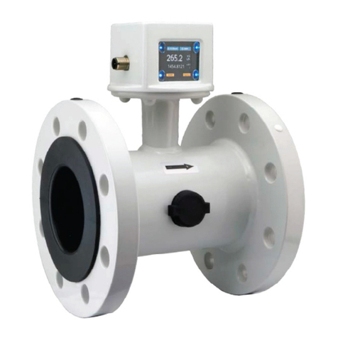
Kobold KME User manual

BA_KME_e // V1.3 // Technical data subject to change // 194573
Operating instructions
KME
Flow meter
for compressed air and gases

KOBOLD Messring GmbH provides no warranty of any kind for this publication and accepts no liability for improper
use of the products described.
This publication might contain technical inaccuracies or typographical errors. The content is revised regularly and is
not subject to change management. The manufacturer reserves the right to modify or change its described products
at any time.
© Copyright KOBOLD Messring GmbH
All rights reserved.
USA
FCC notice:
This device has been tested and found to comply with the conditions for a category B device according to part 15
of the FCC rules and regulations. These conditions were designed to provide adequate protection against EMI in a
residential environment. This device generates, uses and can radiate high-frequency energy. If it is not installed and
used in accordance with the operating instructions, it may cause electromagnetic interference to radio communica-
tions. However there is no guarantee that electromagnetic interference will not occur in a particular installation. If the
device does cause electromagnetic interference to radio or television reception (this can be determined by turning
the device off and on), the user is advised to remedy the interference with the following measures:
• Reorient or relocate the receiving antenna.
• Increase the distance between the device and receiver.
• Connect the device to a different circuit to that of the receiver.
• Consult the dealer or an experienced radio/TV technician.
Caution:
Any changes to the device not expressly approved by an EMI representative could void the user's authority to op-
erate this device.
CANADA
ICES-003 notication:
This category B device complies with Canadian standard ICES-003.

3
Operating instructions for KME ow meter for compressed air and gases
CONTENT
Hardware 4
1 General .................................................................................................................................................4
1.1 Explanation of symbols .................................................................................................................................4
1.2 Safety instructions .........................................................................................................................................4
1.2.1 Intended use ........................................................................................................................................................4
1.2.2 Mounting, start-up and operation .........................................................................................................................5
1.3 Environmental aspects ..................................................................................................................................5
2 Product description ............................................................................................................................6
2.1 Modular design..............................................................................................................................................6
2.1.1 Changing the pipe diameter.................................................................................................................................7
2.2 Functions.......................................................................................................................................................7
2.2.1 Analogue output (OUT 1).....................................................................................................................................7
2.2.2 Switch (alarm) outputs (OUT 1 and OUT 2).........................................................................................................7
2.2.3 Pulse output (OUT 2) and consumption meter.....................................................................................................8
2.2.4 Setting the standard conditions............................................................................................................................8
2.2.5 Lowowcut-off ....................................................................................................................................................8
3 Mechanical installation .......................................................................................................................9
3.1 Installation dimensions ..................................................................................................................................9
3.2 Choosing the appropriate mounting location.................................................................................................9
3.2.1 Process pressure ...............................................................................................................................................10
3.3 Installation position......................................................................................................................................10
3.4 Inlet and outlet measurement path..............................................................................................................11
3.5 Installation of the gauge mounting block .....................................................................................................12
3.5.1 Operating the pipeline without transmitter .........................................................................................................12
3.6 Mounting the transmitter unit into the gauge mounting block......................................................................12
4 Electrical installation ........................................................................................................................13
4.1 Connection diagram ....................................................................................................................................13
4.1.1 Switch and pulse outputs ...................................................................................................................................14
4.2 Bus output (projetcted) ................................................................................................................................14
4.2.1 M-Bus (Meter Bus) (projected)...........................................................................................................................14
4.2.2 Modbus RTU (projected)....................................................................................................................................15
4.3 USBcongurationinterface.........................................................................................................................17
5 Display................................................................................................................................................17
5.1 Measured value display...............................................................................................................................18
5.2 Display menu ..............................................................................................................................................18
6 Error messages .................................................................................................................................20
7 Maintenance.......................................................................................................................................20
7.1 Removing the transmitter from the gauge mounting block..........................................................................20
7.2 Cleaning the sensing head..........................................................................................................................21
7.3 Ordering guide for accessories ...................................................................................................................21
8 Technical data....................................................................................................................................22
8.1 Factory settings of the outputs DN15 / DN20 / DN25..................................................................................23
8.2 Factory settings of the outputs DN32 / DN40 / DN52..................................................................................24
8.3 EU Declaration of Conformance..................................................................................................................25

4
Operating instructions for KME ow meter for compressed air and gases
HARDWARE
1 General
This operation manual is part of the scope of supply and serves for ensuring proper handling and
optimal functioning of the device.
The operation manual shall be read before commissioning the equipment and it shall be provided
to all staff involved in transport, installation, operation, maintenance and repair.
The operation manual may not be used for the purposes of competition without the written
consent of KOBOLD Messring GmbH and may not be forwarded to third parties. Copies may be
made for internal purposes.
All information, technical data and diagrams included in these instructions are based on the infor-
mation available at the time of writing.
1.1 Explanation of symbols
This symbol indicates safety information.
It is essential that all safety information is strictly observed. Failure to comply with this informa-
tion can lead to personal injuries or damage to property. KOBOLD Messring GmbH assumes no
liability if this happens.
This symbol indicates instructions.
The instructions shall be observed in order to reach optimal performance of the device.
1.2 Safety instructions
1.2.1 Intended use
Theowmeter(device)isdedicatedtothemeasurementofcompressedair,non-corrosiveand
non-ammablegasesinpipelines.Pleaseconsultthemanufacturerbeforeemployingthedevice
in wet or dirty gases.
Theowmeterisappropriateforoperationinpressurizedsystemsupto16bar(232psi)(PN16).
Installation, electrical connection, maintenance and commissioning may only be performed by
qualied,trainedandauthorizedstaff.
Use other than described in the present operation manual may represent a security risk for peo-
ple and the entire measuring chain and is therefore not permitted. The manufacturer may not be
made liable for injuries damages caused by inappropriate or non-intended use or installation.
To prevent safety risks and damages, and assure full functionality of the device, the user shall
strictly observe the start-up, inspection and maintenance steps described in this manual. Fur-
thermore, the device may not be manipulated in any other way than described in these operating
instructions, and may not be exposed to any excessive mechanical stress.
Theowmetermaybeoperatedonlyundertheambientconditionsasdenedinthetechnical
data sheet. Use under other ambient conditions may lead to device malfunctions.

5
Operating instructions for KME ow meter for compressed air and gases
1.2.2 Mounting, start-up and operation
Theowmeterhasbeenproducedunderstateoftheartmanufacturingconditions,hasbeen
thoroughlytestedandhasleftthefactoryfulllingallsafetycriteria..
The manufacturer has taken all precautions to ensure safe operation of the device. The user
must ensure that the device is set up and installed in a manner that does not have a negative
effect on its safe use.
The user is responsible for observing all applicable safety guidelines, local and international, with
respect to safe installation and operation on the device. This operating manual contains informa-
tion and warnings that must be observed by the user in order to ensure safe operation.
• Mounting,start-up,operationandmaintenanceofthedevicemaybeperformedbyqualied
staffonly.Suchstaffmustbeauthorizedbytheplantoperatortocarryoutthementioned
activities.
• Thequaliedstaffmusthavereadandunderstoodthisoperatingmanualandmustfollowthe
instructions contained within.
• Allprocessandelectricalconnectionsshallbethoroughlycheckedbyauthorizedstaffbefore
putting the system into operation.
• Do not install or start start-up a device supposed to be faulty. Make sure that such devices are
not accidentally used by marking them clearly as faulty.
• Afaultydevicemayonlybeinvestigatedandpossiblyrepairedbyqualied,trainedand
authorizedstaff.Ifthefaultcannotbexed,thedeviceshallberemovedfromthesystem.
• Service operations other than described in this operating manual may only be performed by the
manufacturer.
Disclaimer
Themanufacturerorhisauthorizedagentcanbeonlybeheldliableincaseofwillfulorgross
negligence. In any case, the scope of liability is limited to the corresponding amount of the order
issued to the manufacturer. The manufacturer assumes no liability for damages incurred due to
failure to comply with the applicable regulations, operating instructions or the operating condi-
tions. Consequential damages are excluded from the liability.
1.3 Environmental aspects
Products from KOBOLD Messring GmbH are developed and manufactured observing of all relevant re-
quirements with respect to environment protection. Please observe local regulations for the device disposal.
For disposal, the individual components of the device must be separated according to local recycling
regulations. The electronics shall be disposed of correctly as electronics waste.

6
Operating instructions for KME ow meter for compressed air and gases
2 Product description
TheKMEowmeteroperatesonthethermalmassowmeasurementprincipleandissuitable
formeasuringtheowofcompressedairandgasesinpipelines.Itcanbeusedformeasuring
the consumption of compressed air, nitrogen, argon, oxygen, CO2 or other non-corrosive and
non-ammablegases.
TheKMEmeasuresthevolumeowunderstandardconditions.Thestandardconditions
according to DIN 1343 (1013.25 mbar; 0 °C) are factory-set. Additionally, KME measures also the
massow,thestandardizedowandthetemperature.
KMEhastwosignaloutputswhichcanbeconguredasananalogueoutput(current),switch
output or pulse output for consumption metering.
The KME features an integrated consumption meter. The consumption volume can be shown on
the display and is retained even if the supply voltage is interrupted.
Transmitter
Display (optional)
Gauge mounting block
Output
•Analogue
•2 switch outputs
•Pulse output
•Modbus RTU (projected)
•M-Bus (projected)
Sensing head
2.1 Modular design
One and the same transmitter can be used for each of
three pipe diameters:
KME-715/-720/-725: DN15 (1/2“) / DN20 (3/4“) / DN25 (1“)
KME-732/-740/-750: DN32 (1-1/4“) / DN40 (1-1/2“) / DN50 (2“)
The pipe diameter is easily changed via the display
menuortheConguratorsoftware.
Once the gauge mounting block is mounted in the
pipeline, the transmitter can be installed and removed
without disconnecting the pipeline. As a result, the KME
is also ideal for temporary measurements or mobile use.
The sealing plug included in the scope of supply allows for operating the compressed air or gas
network even without the transmitter.

7
Operating instructions for KME ow meter for compressed air and gases
2.1.1 Changing the pipe diameter
Upon delivery, the factory setting of the transmitter corresponds to the pipe diameter as ordered. The set-
ting must match the gauge mounting block. For use use with a gauge mounting block of different diameter,
the transmitter setting shall be correspondingly changed, otherwise it would lead to relevant measurement
errors.
Fig. 1 Pipe diameter on gauge mounting block
Pipe diameter
label
The pipe diameter setting of the transmitter can be viewed on the status page of the optional
display and can be changed using the “Pipe diameter” menu, see § 5, page 17.
Alternatively,thepipediametersettingcanbeviewedandchangedusingtheProductCongura-
tor Software.
2.2 Functions
2.2.1 Analogue output (OUT 1)
Theanaloguecurrentoutput(factorysetting4...20mAor0...20mA)isusedfortheactualowor
temperaturemeasuredvalues.Theanalogueoutputisfreelycongurableandscalableviathe
displaymenuortheProductConguratorSoftware.
The analogue output features an error message function according to NAMUR NE43. In the event of a
faultysensinghead,theoutputsignalwillfreezeat21mA.
2.2.2 Switch (alarm) outputs (OUT 1 and OUT 2)
TheswitchoutputscanbesetviathedisplaymenuortheProductConguratorSoftware.One
can select between “hysteresis mode” or “window mode” as well as between normally closed
(NC) or normally open (NO) contact.
NC (normally
closed contact)
NO (normally open
contact)
Switch point
Hysteresis
t
Nm³/h
0
1
0
1
Fig. 2 Hysteresis mode
NC (normally
closed contact)
NO (normally open
contact)
Switch point 2
Hysteresis 2Hysteresis 1
Switch point 1
t
Nm3/h
0
1
0
1
Fig. 3 Window mode

8
Operating instructions for KME ow meter for compressed air and gases
2.2.3 Pulse output (OUT 2) and consumption meter
TheKMEowmeterfeaturesanintegratedmeterwithpulseoutput,whichtotalizestheconsump-
tion of compressed air or gas.
WiththedisplaymenuortheProductConguratorSoftwaretheusercanset:
• Pulse duration: 0.02...2 seconds
• Pulse value: 0.1...1,000 m³
The pulse - pause ratio must be at least 1:2. This means that the time between pulses must be at
least twice the pulse duration.
The minimum time between two pulses is 2 s.
t
OUT 2
1/3 min. 2/3
≥ 2 s
Fig. 4 Pulse-pause ratio
The pulse duration and the pulse value can be calculated with following MIN/MAX-Formula:
Calculating the min. “pulse value” or the max. “pulse duration”:
IMPW_MIN = NORMV_MAX [m³/h] * IMPL [s] / 1200
IMPL_MAX = IMPW [m³] * 1200 / NORMV_MAX [m³/h]
IMPW pulse value [m³]
IMPL pulse duration [s]
IMPW_MIN min. value for pulse value [m³]
IMPL_MAX max. pulse duration [s]
NORMV_MAX max.expectedstandardvolumeow[m³/h]
Thetotalizedconsumptionisstoredeveryminuteandisretainedevenifthesupplyvoltageis
interrupted.
Thetotalizedconsumptioncanbeshownonthedisplay.Aresetoftheconsumptionmetercanbe
performedviadisplaymenuorviaProductConguratorSoftware.
Maximum consumption value on the display:
The consumption value on the display is limited at 999,999,999.0 m3. Above this, the display
shows “LCD maximum”, while the internally the consumption is metered normally till the
maximum value of 3.4 * 1038 m3. Values above 999,999,999.0 m3can be read with the Product
ConguratorSoftware.
2.2.4 Setting the standard conditions
ThestandardvolumeowcalculationisbasedonthestandardconditionsstoredintheKME
transmitter unit. The factory setting for the standard conditions complies with DIN 1343:
P0= 1013.25 mbar, t0= 0 °C
ThestandardconditionscanbechangedviadisplaymenuorviaProductConguratorSoftware.
2.2.5 Low ow cut-off
Verysmall(insignicant)owvaluescanbesuppressedbysettingashutdownthreshold.
Measured values below the shutdown threshold have no effect on the output signal, dis-
play and consumption meter.
The minimum shutdown value can be set in m³/h or ft³/min.

9
Operating instructions for KME ow meter for compressed air and gases
3 Mechanical installation
3.1 Installation dimensions
Gauge
mounting
block
Thread
Rpor NPT
DN15 1/2"
DN20 3/4"
DN25 1"
DN321) 1-1/4ʺ
DN40 1-1/2ʺ
DN50 2ʺ
1) only Rpthread
Internal thread:
according to EN 10226 (old DIN 2999)
or NPT
Internal thread:
according to EN 10226 (old DIN 2999)
or NPT
M12 x 1
M12 x 1
50
88,5
84,5
123
100
100
50
80
KME-715/-720/-725
KME-732/-740/-750
3.2 Choosing the appropriate mounting location
• The mounting location site shall be easily accessible and free of vibration.
• A minimum clearance of 150 mm (5.9”) shall be observed around the mounting location for
installing / removing the transmitter unit of the E741.
• Theambienttemperatureshallnotexceedthespeciedlimits.Consideralsothepossibleheat
radiation.
• Air (medium) purity at the mounting location shall comply to ISO 8573-1:2010, at least Class
3.4.4.
• The medium and the ambient conditions at the mounting location shall be non-condensing.
• In compressed air networks, KME shall be installed after the air dryer. In the absence of a dry-
er,KMEshallbeinstalledafterthecondensateseparatorandappropriatelters.
• Observetheowdirectioninthepipe.
• Observe the recommended inlet and outlet path length. These are relevant for measurement
accuracyasspeciedintheKMEdatasheet.
• KMEshallbelocatedasfaraspossiblefromowdisturbances,forinstanceatan
appropriate distance before valves.

10
Operating instructions for KME ow meter for compressed air and gases
3.2.1 Process pressure
The pressure in the pipeline may not exceed 16 bar (232 psi).
Before mounting or removing the transmitter, the pipeline must be
depressurised.
Due to its measuring principle, the measurement accuracy of the KME is quasi-independent of
the actual process pressure. Besides, the device is factory adjusted at 7 bar (102 psi) absolute
pressure. For normal requirements pressure compensation is not necessary. For best measure-
mentaccuracy,theactualworkingpressurecanbesetviadisplaymenuorviaProductCongu-
rator Software.
3.3 Installation position
Vertical mounting
+
Horizontalmounting,transmitterattop
+
Horizontalmounting,transmitterhorizontal
+
Horizontalmounting,transmitteratbottom
-
Flow Direction
Flow Direction
Flow Direction
Flow Direction
Flow Direction
Flow Direction
Flow Direction
Flow Direction
+ ... Recommended installation position
- ...... Not recommended

11
Operating instructions for KME ow meter for compressed air and gases
3.4 Inlet and outlet measurement path
Formeasurementaccuracyaccordingtoproductspecication,theKMEowmetershallbelocat-
edasfaraspossiblefromowdisturbancescausedforinstancebypipereductionsorexpan-
sions, bends, T-pieces, valves or sliders. This can be accomplished by observing a minimum inlet
and outlet path length, which depends on both the nature of disturbance and the pipe diameter.
• Theowmetershallbelocatedbeforevalvesorsliders.
• With light gases the inlet paths need to be extended.
Flow Direction
Pipe diameter (DN)
Outlet path Inlet path
Flow direction
Type
(DN = pipe diameter)
Inlet path Outlet path
Extension 15 x DN 5 x DN
Reduction 15 x DN 5 x DN
90° elbow 20 x DN 5 x DN
Two 90° elbows, on
one level 25 x DN 5 x DN
Two 90° elbows, on
two levels, T-piece 30 x DN 5 x DN
Valve, slider 50 x DN 5 x DN

12
Operating instructions for KME ow meter for compressed air and gases
3.5 Installation of the gauge mounting block
The gauge mounting block is symmetrical and can be installed in the pipeline irrespective of the
owdirection.
• All connections must be properly sealed and checked for tightness.
• The thread seals shall not impact on the cross section of the pipe or of the block.
3.5.1 Operating the pipeline without transmitter
To operate the pipeline without the transmitter unit, the opening of gauge mounting block which
accommodates the sensing head can be closed using the sealing plug included in the scope of
supply(g.5).ThesealingplughasaTuok®coating(http://www.bossard.com)anddoesnot
require any additional seal.
Mount the sealing plug with a torque of min. 28 Nm.
Under normal operation with transmitter installed, the sealing plug shall be placed for safe keep-
ingintotheopeningatthesideofthegaugemountingblock(g.6).
Fig. 5 Gauge mounting block with sealing
plugs Fig. 6 Sealing plug in park position
3.6 Mounting the transmitter unit into the gauge mounting block
Depressurize the pipeline before mounting or removing the transmitter
unit.
In case the gauge mounting block has been operated without transmitter, remove the sealing
plug with a WAF 13 spanner.
Removetheprotectivecapfromthesensinghead(g.7)andinsertcarefullythesensingheadof
the transmitter into the gauge mounting block.
Fig. 7 Remove protective cap

13
Operating instructions for KME ow meter for compressed air and gases
Makesurethatthedirectionarrowonthetransmitterunitscorrespondstotheowdirectionin
the pipeline. Failure to comply with this may lead to additional measurement error of ±3 % of the
measured value.
Complete the mounting by tightening the mounting screws with max. torque 6 Nm using the 4
mmhexkeyincludedinthescopeofsupply(g.8).
Fig. 8 Tighten mounting screws
4 Electrical installation
TheelectricalinstallationoftheKMEshallbeperformedbyqualiedstaffonly.Observeallapplicable
national and international requirements for the installation of electrical devices as well as power supply
according to EN 50178, SELV, PELV.
4.1 Connection diagram
Fig. 9 M12 connector
M12 4-pin connector according to
IEC 61076-2-101
Analogue/switch/
pulse output
1...V+
2...Output 1
3...GND
4...Output 2
Modbus RTU
(projected)
1...V+
2...RS485 A (=D+)
3...GND
4...RS485 B (=D-)
M-Bus / Meter bus
(projected)
1...V+
2...M-Bus
3...GND
4...M-Bus
1 2
34
M12 connector
on the transmitter

14
Operating instructions for KME ow meter for compressed air and gases
4.1.1 Switch and pulse outputs
SwitchandpulseoutputsareNOTpotential-freeandincludeinternalpull-downresistors(g.10)
V+
GND
GND
10k 10k
OUT 1
OUT 2
Fig. 10 Switch/pulse output
4.2 Bus output (projected)
4.2.1 M-Bus (Meter Bus) (projected)
The M-Bus (Meter Bus) is a field bus for recording consumption data. Transmission runs serially
on a reverse polarity protected two-wire line. The KME flow meter as M-Bus slave requires a sep-
arate supply voltage. There is no prescribed specific topology (line or star) for the wiring. Normal
phone cable of type J-Y(St)Y Nx2x0.8 mm can be used. The max. cable length per segment
(primary addressed) is 250 m (3.28 ft).
The table below shows the structure of the consumption data sent by the transmitter:
Header
68 Start of the telegram
4F 4F L-eld(length)
68 Second starting signal
08 C-eld(RSP_UD)
XX A-eld(address)
Start user data
72 CI-eld(variabledatastructure)
XX XX XX XX Identicationnumber
A5 16 Manufacturer (0x16A5 … EUE)
01 Version
09 Medium (9 … compressed air)
XX Access number (consecutive)
00 Status
00 00 Signature
Data record 1: Volume ow
05 DIF (32 bit real)
3E VIF(volumeowinm³/h)
XX XX XX XX Cur. measured value
Data record 2: Temperature
05 DIF (32 bit real)
5B VIF (temperature in °C)
XX XX XX XX Cur. measured value
Data record 3: Mass ow
05 DIF (32 bit real)
53 VIF(massowinkg/h)
XX XX XX XX Cur. measured value
Data record 4: Consumption meter status
05 DIF (32 bit real)
16 VIF (volumes in m³)
XX XX XX XX Cur. consumption value
Data record 5: Flow velocity
05 DIF (32 bit real)
7F VIF(manufacturer-specicinm/s)
XX XX XX XX Cur. measured value
Data record 6: Volume ow
04 DIF (32 bit integer)
3B VIF(volumeowin10-³m³/h)
XX XX XX XX Cur. measured value
Data record 7: Temperature
04 DIF (32 bit integer)
59 VIF (temperature in 10-² °C)
XX XX XX XX Cur. measured value
Data record 8: Mass ow
04 DIF (32 bit integer)
51 VIF(massowin10-²kg/h)
XX XX XX XX Cur. measured value
Data record 9: Consumption meter status
07 DIF (64 bit integer)
13 VIF (volumes in 10-³ m³)
XX XX XX XX
XX XX XX XX
Cur. consumption value
Data record 10: Flow velocity
04 DIF (32 bit integer)
7F VIF(manufacturer-specicin10-²
m/s)
XX XX XX XX Cur. measured value
End user data
XX Checksum
16 End of telegram

15
Operating instructions for KME ow meter for compressed air and gases
Secondary addressing:
Inadditiontoprimaryaddressing,theKMEowmeterprovidestheoptionofsecondaryaddress-
ing.Thesecondaryaddressusestheeldsofidenticationnumber,manufacturer,versionand
medium.TheM-BusStandardhttp://www.m-bus.com/les/MBDOC48.PDFdescribestheexact
sequence of the secondary addressing.
Data transmission:
Factory settings Adjustable values
Baud rate 2400 600, 1200, 2400, 4800, 9600
Data bits 8 8
Parity EVEN None, odd, even
Stop bits 11 or 2
Slave address 240 0...254
For several devices on the bus the max. recommended baud rate is 9600.
4.2.2 Modbus RTU (projected)
KMEowmetercanbeoperatedinaModbusRTUnetworkwithmax.32devices.Writing0into
the corresponding register will reset the MIN/MAX values and the consumption meter.
For Modbus protocol settings see Application Note Modbus AN0103.
Modbus Map:
Register
[DEC]
Protocol
address [HEX]
Measured value Unit Type
Read registers (function code 0x03 / 0x04)
30501 1F4 Temperature °C 32-bit float
30503 1F6 Temperature °F 32-bit float
30507 1FA Standard flow Nm/s 32-bit float
30509 1FC Standard flow SFPM 32-bit float
30511 1FE Mass flow kg/h 32-bit float
30513 200 Mass flow kg/min 32-bit float
30517 204 Standard volume flow Nm³/h 32-bit float
30519 206 Standard volume flow Nm³/min 32-bit float
30521 208 Standard volume flow l/min 32-bit float
30523 20A Standard volume flow l/s 32-bit float
30525 20C Standard volume flow SCFM 32-bit float
30529 210 Consumption meter status m³ 64-bit-double
30533 214 Consumption meter status ft³ 64-bit-double
31001 3E8 MIN value temperature °C 32-bit float
31003 3EA MIN value temperature °F 32-bit float
31007 3EE MIN value standard flow Nm/s 32-bit float
31009 3F0 MIN value standard flow SFPM 32-bit float
31011 3F2 MIN value mass flow kg/h 32-bit float
31013 3F4 MIN value mass flow kg/min 32-bit float
31017 3F8 MIN value standard volume flow Nm³/h 32-bit float
31019 3FA MIN value standard volume flow Nm³/min 32-bit float
31021 3FC MIN value standard volume flow l/min 32-bit float
31023 3FE MIN value standard volume flow l/s 32-bit float
31025 400 MIN value standard volume flow SCFM 32-bit float
31501 5DC MAX value temperature °C 32-bit float
31503 5DE MAX value temperature °F 32-bit float
31507 5E2 MAX value standard flow Nm/s 32-bit float
31509 5E4 MAX value standard flow SFPM 32-bit float
31511 5E6 MAX value mass flow kg/h 32-bit float
31513 5E8 MAX value mass flow kg/min 32-bit float
31517 5EC MAX value standard volume flow Nm³/h 32-bit float
31519 5EE MAX value standard volume flow Nm³/min 32-bit float
31521 5F0 MAX value standard volume flow l/min 32-bit float
31523 5F2 MAX value standard volume flow l/s 32-bit float
31525 5F4 MAX value standard volume flow SCFM 32-bit float

16
Operating instructions for KME ow meter for compressed air and gases
Write registers (function code 0x06)
60001 0 Reset MIN value temperature 16-bit integer
60002 1 Reset MIN value standard flow 16-bit integer
60003 2 Reset MIN value mass flow 16-bit integer
60004 3 Reset MIN value standard volume flow 16-bit integer
60005 4 Reset MAX value temperature 16-bit integer
60006 5 Reset MAX value standard flow 16-bit integer
60007 6 Reset MAX value mass flow 16-bit integer
60008 7 Reset MAX value standard volume flow 16-bit integer
60009 8 Reset consumption meter 16-bit integer
Data transmission:
Factory settings Adjustable values
Baud rate 9600 9600, 19200, 38400
Data bits 8 8
Parity EVEN None, odd, even
Stop bits 11 or 2
Slave address 240 1...247
The recommended baud rate for several devices in the Modbus RTU network is 9600.
Bus termination resistor:
BusterminationisrequiredforthelastowmeterinaModbusRTUnetwork.The120Ohmtermination
resistorislocatedbehindtheblindoftheUSBportandcanbeswitchedonandoff(g.11)
Fig. 11 Bus termination resistor

17
Operating instructions for KME ow meter for compressed air and gases
4.3 USB conguration interface
ThemicroUSBportislocatedbehindablindcover(g.12and13)
Blind coupling USB cable
Fig. 12 Remove the blind cover Fig. 13 Plug in the USB cable
For KME setup and configuration via USB interface it is necessary to install the Product
Configuration Software on a personal computer.
5 Display
The LCD-display (optional) shows the actual measured values and the overall consumption. The
completeKMEsetupandcongurationcanbeperformedwiththecontrolkeysandintuitive,self
explanatory menu guidance.
If the settings are changed during operation, it may affect the function of the system. Ensure
that it will not result in any system malfunctions.
The display orientation can be changed in 90° steps via the settings menu to match the mounting
positionofKME(g.14and15)
Fig. 14 Horizontal display Fig. 15 Vertical display

18
Operating instructions for KME ow meter for compressed air and gases
5.1 Measured value display
Upon power on the display is in measuring mode and shows the measured values. One can
selectamongsixmeasurandsandastatuspage(g.16and17).
Abbreviations for measurands:
T ... Temperature
V‘n... Standardvolumeow
m‘... Massow
Qn ... Consumption
vn... Standardow
Fig. 16 Status display Fig. 17 Measured value display
Explanation of the symbols:
... Output 1 set to analogue output
... Output 2 set to pulse output/consumption
... Output 1 set to switching output; status OFF
... Output 1 set to switching output; status ON
... Output 2 set to switching output; status OFF
... Output 2 set to switching output; status ON
5.2 Display menu
The display menu can be navigated and settings made using the four control keys allow for easy
navigation and intuitive device setup.
... SELECT/SAVE
... BACK/CANCEL
... UP/increase value
... DOWN/decrease value

19
Operating instructions for KME ow meter for compressed air and gases
Status
Measurand 1
Measurand 2
Output 1
Output 2
Pipe diameter
DNxx
Display
Process param.
Low-flow cut-off
Counter reading
Min/Max
Settings
Measurand 3
Measurand 4
Measurand 5
Measurand 6
Measuring mode Setup mode
Fig. 18 Display - menu guidance
Output 1
Congurationforoutput1:analogueorswitchoutput,measurand,scaleandswitchsetup.
Output 2
Congurationforoutput2:switchorpulseoutput,measurand,switchsetup.
Pipe diameter
Set the pipe diameter, see 2.1.1 on page 7
Display
Set the measuring mode and the display orientation.
Process parameter
Set the operating pressure and the standard conditions (see 2.2.4, page 8).
Low-ow cut-off
Setthecut-offthresholdforleakowvolumesuppression,(see2.2.5,page8).
Counter reading
Display or reset the consumption meter.
Min/Max
Display or delete the min/max memory.
Settings
• Set the language.
• Set the averaging for measured value of the analogue output signal between 1 and 50. The
measuring rate is 0.1 seconds).
The response time t90 < 2 seconds according to the specs is achieved for averaging less than
10 values. With averaging 50 values the response time is 5 seconds.

20
Operating instructions for KME ow meter for compressed air and gases
6 Error messages
Error messages are available on the status page of the display and at the status LEDs.
Fig. 19 Status LED - error message
Green LED Red LED
0: no error / green LED ashes
1: EEPROM faulty / green LED ashes, red LED lights up
Cause: The EEprom for storing the consumption meter status and the MIN/MAX values
is faulty.
Consequence: The consumption meter status and the MIN/MAX values are no longer available.
All current measured values are shown on the display. The analogue, switch and
pulse outputs operate normally.
Remedy: Return the device to the manufacturer for service.
2: Display error / green LED ashes, red LED lights up
Cause: The display or the communication with the display is faulty.
Consequence: Analogue, switch and pulse outputs operate normally.
Remedy: Return the device to the manufacturer for service.
4: Sensor fault / green LED ashes, red LED ashes
Cause: The sensing head is faulty.
Consequence: Allmeasurandsonthedisplayarefrozenatthelowestpossiblevaluee.g.-20°C
(-4 °F)or0m³/h.Theanalogueoutputisfrozenat21mA(NAMURNU43).
Remedy: Return the device to the manufacturer for service.
7 Maintenance
ItisrecommendedtocalibratetheKMEowmeteronayearlybase.
For use with polluted media, the sensing head should be periodically cleaned.
7.1 Removing the transmitter from the gauge mounting block
Depressurize the pipeline before mounting or removing the transmitter
unit.
Ensurethatthelineisdepressurizedandreleasethemountingscrewsofthetransmitterunit
(g.20and21).
Table of contents
Other Kobold Measuring Instrument manuals

Kobold
Kobold DAG-A1V User manual

Kobold
Kobold DRZ series User manual

Kobold
Kobold DAG-M3T User manual

Kobold
Kobold KAL-A User manual

Kobold
Kobold HND-P210 User manual

Kobold
Kobold NBK-01 User manual

Kobold
Kobold Heinrichs K12 User manual

Kobold
Kobold NMF User manual

Kobold
Kobold HND-F205 User manual

Kobold
Kobold DAG-M1V Series User manual

Kobold
Kobold BGN User manual

Kobold
Kobold DAG-A3V User manual

Kobold
Kobold DRS-9180 Series User manual

Kobold
Kobold KSM-**001 User manual

Kobold
Kobold DAG-A14 User manual

Kobold
Kobold KEC-1 User manual

Kobold
Kobold HND-P Series User manual

Kobold
Kobold OVZ 1 Series User manual

Kobold
Kobold KDF-2 Series User manual

Kobold
Kobold DF KL Series User manual