TELEDYNE API T703U User manual

USER MANUAL
MODELS T703 and T703U
PHOTOMETRIC O3CALIBRATOR
© TELEDYNE ADVANCED POLLUTION INSTRUMENTATION (TAPI)
9480 CARROLL PARK DRIVE
SAN DIEGO, CALIFORNIA 92121-5201
USA
Toll-free Phone:
800-324-5190
Phone:
858-657-9800
Fax:
858-657-9816
Email:
api-sales@teledyne.com
Website:
http://www.teledyne-api.com/
Copyright 2010-201507223D DCN7107
Teledyne Advanced Pollution Instrumentation 24 July 2015


i
NOTICE OF COPYRIGHT
© 2010-2015 Teledyne Advanced Pollution Instrumentation, Inc. All rights reserved.
TRADEMARKS
All trademarks, registered trademarks, brand names or product names appearing in this document are the
property of their respective owners and are used herein for identification purposes only.
07223D DCN7107

ii
This page intentionally left blank.
07223D DCN7107

iii
SAFETY MESSAGES
Important safety messages are provided throughout this manual for the purpose of avoiding personal
injury or instrument damage. Please read these messages carefully. Each safety message is associated
with a safety alert symbol, and placed throughout this manual and inside the instrument. The symbols
with messages are defined as follows:
CAUTION
This instrument should only be used for the purpose and in the manner
described in this manual. If you use this instrument in a manner other than
that for which it was intended, unpredictable behavior could ensue with
possible hazardous consequences.
NEVER use a gas analyzer to sample any combustible gas(es)!
Note
Technical Assistance regarding the use and maintenance of this instrument or any other
Teledyne API product can be obtained by contacting Teledyne API’s Technical Support
Department:
Telephone: 800-324-5190
Email: sda_techsupport@teledyne.com
or by accessing various service options on our website at http://www.teledyne-api.com/
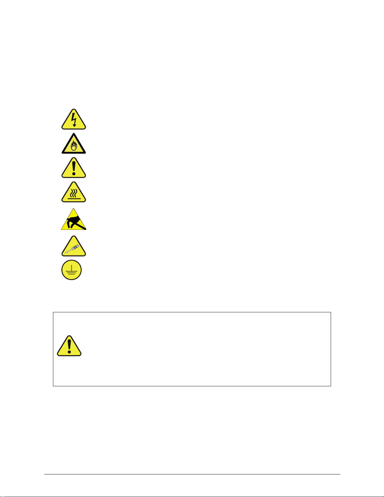
WARNING: Electrical Shock Hazard
HAZARD: Strong oxidizer
GENERAL WARNING/CAUTION: Read the accompanying message for
specific information.
CAUTION: Hot Surface Warning
Do Not Touch: Touching some parts of the instrument without
protection or proper tools could result in damage to the part(s) and/or the
instrument.
Technician Symbol: All operations marked with this symbol are to be
performed by qualified maintenance personnel only.
Electrical Ground: This symbol inside the instrument marks the central
safety grounding point for the instrument.
07223D DCN7107
iv
CONSIGNES DE SÉCURITÉ
Des consignes de sécurité importantes sont fournies tout au long du présent manuel dans le but d‟éviter
des blessures corporelles ou d‟endommager les instruments. Veuillez lire attentivement ces consignes.
Chaque consigne de sécurité est représentée par un pictogramme d‟alerte de sécurité; ces pictogrammes
se retrouvent dans ce manuel et à l‟intérieur des instruments. Les symboles correspondent aux consignes
suivantes :
AVERTISSEMENT : Risque de choc électrique
DANGER : Oxydant puissant
AVERTISSEMENT GÉNÉRAL / MISE EN GARDE : Lire la consigne
complémentaire pour des renseignements spécifiques
MISE EN GARDE : Surface chaude
Ne pas toucher : Toucher à certaines parties de l‟instrument sans protection ou
sans les outils appropriés pourrait entraîner des dommages aux pièces ou à
l‟instrument.
Pictogramme « technicien » : Toutes les opérations portant ce symbole doivent
être effectuées uniquement par du personnel de maintenance qualifié.
Mise à la terre : Ce symbole à l‟intérieur de l‟instrument détermine le point central
de la mise à la terre sécuritaire de l‟instrument.
MISE EN GARDE
Cet instrument doit être utilisé aux fins décrites et de la manière décrite dans
ce manuel. Si vous utilisez cet instrument d’une autre manière que celle pour
laquelle il a été prévu, l’instrument pourrait se comporter de façon imprévisible
et entraîner des conséquences dangereuses.
NE JAMAIS utiliser un analyseur de gaz pour échantillonner des gaz
combustibles!
07223D DCN7107
v
WARRANTY
WARRANTY POLICY (02024G)
Teledyne Advanced Pollution Instrumentation (TAPI), a business unit of Teledyne
Instruments, Inc., provides that:
Prior to shipment, TAPI equipment is thoroughly inspected and tested. Should
equipment failure occur, TAPI assures its customers that prompt service and support
will be available.
COVERAGE After the warranty period and throughout the equipment lifetime, TAPI stands ready
to provide on-site or in-plant service at reasonable rates similar to those of other
manufacturers in the industry. All maintenance and the first level of field
troubleshooting are to be performed by the customer.
NON-TAPI MANUFACTURED EQUIPMENT
Equipment provided but not manufactured by TAPI is warranted and will be repaired
to the extent and according to the current terms and conditions of the respective
equipment manufacturer‟s warranty.
PRODUCT RETURN All units or components returned to Teledyne API should be properly packed for
handling and returned freight prepaid to the nearest designated Service Center.
After the repair, the equipment will be returned, freight prepaid.
The complete Terms and Conditions of Sale can be reviewed at
http://www.teledyne-api.com/terms_and_conditions.asp
CAUTION –Avoid Warranty Invalidation
Failure to comply with proper anti-Electro-Static Discharge (ESD) handling and
packing instructions and Return Merchandise Authorization (RMA) procedures
when returning parts for repair or calibration may void your warranty. For anti-ESD
handling and packing instructions please refer to the manual, Fundamentals of
ESD, PN 04786, in its “Packing Components for Return to Teledyne API‟s
Customer Service” section. The manual can be downloaded from our website at
http://www.teledyne-api.com under Help Center > Product Manuals in the Special
Manuals section; RMA procedures are under Help Center > Return Authorization.
07223D DCN7107

vi
ABOUT THIS MANUAL
Presented here is information regarding the documents that are included with this manual (Structure), its
history of release and revisions (Revision History), how the content is organized (Organization), and the
conventions used to present the information in this manual (Conventions Used).
STRUCTURE
This T703/T703U manual, PN 07223, is comprised of multiple documents, assembled in PDF format, as
listed below.
Part No.
Rev
Name/Description
07223
D
T703 and T703U Photometric Calibrator Operation Manual (the main body of this manual)
05745
F
Menu trees and software documentation (inserted as Appendix A of this manual)
07224
A
T703 Spare Parts List (located in Appendix B of this manual)
07747
A
T703U Spare Parts List (located in Appendix B of this manual)
05747
E
Appendix C, Repair Questionnaire
Documents and Schematics included in Appendix D of this manual:
073600100
A
T703 Interconnect List
07360
A
T703 Interconnect Diagram
04354
D
SCH, PCA 04003, PRESS/FLOW
04420
B
SCHEMATIC, UV DET PREAMP
04421
A
SCHEMATIC, UV LAMP SUPPLY
04422
A
SCHEMATIC, DC HEATER/THERMISTOR
04524
E
SCHEMATIC, RELAY CARD
05803
B
SCH, PCA 05802, MOTHERBOARD, GEN-5
06698
D
SCH, PCA 06697, INTRFC, LCD TCH SCRN
06882
B
SCH, LVDS TRANSMITTER BOARD
06731
A
SCH, AUXILLIARY-I/O BOARD
Note
We recommend that this manual be read in its entirety before any attempt is made to operate the
instrument.
07223D DCN7107

7
TABLE OF CONTENTS
1. INTRODUCTION.................................................................................................................15
1.1. T703/T703U Calibrator Overview................................................................................................................15
1.2. Options ........................................................................................................................................................16
2. SPECIFICATIONS AND APPROVALS ..............................................................................17
2.1. Specifications ..............................................................................................................................................17
2.2. Approvals and Certifications........................................................................................................................18
Safety ....................................................................................................................................................182.2.1. EMC.......................................................................................................................................................182.2.2. Other Type Certifications.......................................................................................................................182.2.3.
3. GETTING STARTED...........................................................................................................19
3.1. Unpacking and Initial Setup.........................................................................................................................19
Front, Rear, and Internal Calibrator Description ...................................................................................203.1.1.
3.2. Electrical Connections.................................................................................................................................28
Power Connection.................................................................................................................................283.2.1. Analog output Test Channel Connections.............................................................................................283.2.2. Connecting the Status Outputs .............................................................................................................293.2.3. Connecting the Control Inputs...............................................................................................................303.2.4. Connecting the Control Outputs............................................................................................................323.2.5. Communication Connections ................................................................................................................333.2.6. Ethernet Connection ......................................................................................................................333.2.6.1. USB Option Connection.................................................................................................................333.2.6.2. RS-232 and RS485 Connection.....................................................................................................333.2.6.3. Multidrop Network Connection.......................................................................................................333.2.6.4.
3.3. Pnenumatic Connections.............................................................................................................................34
Dry Air In................................................................................................................................................34
3.3.1. Zero Air In..............................................................................................................................................343.3.2. Output Manifold .....................................................................................................................................353.3.3. Exhaust..................................................................................................................................................353.3.4. Measuring An External Ozone Source..................................................................................................353.3.5.
3.4. Initial Operation ...........................................................................................................................................35
Start-Up .................................................................................................................................................353.4.1. Warm Up ...............................................................................................................................................353.4.2. Warning Messages................................................................................................................................363.4.3. Functional Check...................................................................................................................................383.4.4. Operating Modes for the O3Generator .................................................................................................393.4.5. CNST (CONSTANT)......................................................................................................................393.4.5.1. BNCH (BENCH).............................................................................................................................393.4.5.2.
Setting the O3Generator Mode.............................................................................................................393.4.6. Setting the output Flow Rate.................................................................................................................40
3.4.7. Calculating Output Flow Rate ........................................................................................................403.4.7.1. Output Flow Setup .........................................................................................................................403.4.7.2.
4. OPERATING THE CALIBRATOR ......................................................................................41
4.1. Test Functions .............................................................................................................................................42
4.2. Overview of Operating modes.....................................................................................................................43
4.3. Standby Mode .............................................................................................................................................44
4.4. General Information about the GENERATE mode......................................................................................45
GENERATE > AUTO: Basic Generation of Calibration Gas.................................................................454.4.1.
4.5. Automatic Calibration Sequences ...............................................................................................................45
SETUP > SEQ: Programming Calibration Sequences..........................................................................464.5.1. Activating a Sequence from the T703/T703U Front Panel ............................................................474.5.1.1. Naming a Sequence ......................................................................................................................484.5.1.2. Setting the Repeat Count for a Sequence .....................................................................................494.5.1.3.
07223D DCN7107

8
Using the Internal Clock to Trigger Sequences ............................................................................50
4.5.1.4. Setting Up Control Inputs for a Sequence .....................................................................................534.5.1.5. Setting Up Control Outputs for a Sequence ..................................................................................544.5.1.6. Setting the Progress Reporting Mode for the Sequences .............................................................554.5.1.7.
Adding Sequence Steps........................................................................................................................564.5.2. The GENERATE Step....................................................................................................................574.5.2.1. The STANDBY Step ......................................................................................................................584.5.2.2. The DURATION Step.....................................................................................................................584.5.2.3. The EXECSEQ Step......................................................................................................................594.5.2.4. The CC OUTPUT Step ..................................................................................................................604.5.2.5. Deleting or Editing an Individual Step in a Sequence....................................................................614.5.2.6.
Deleting a Sequence .............................................................................................................................624.5.3.
4.6. SETUP > CFG.............................................................................................................................................63
4.7. SETUP > CLK..............................................................................................................................................64
Setting the Internal Clock‟s Time and Day ............................................................................................64
4.7.1. Adjusting the Internal Clock‟s speed .....................................................................................................654.7.2.
4.8. SETUP > PASS...........................................................................................................................................66
4.9. SETUP > DIAG > TEST CHAN OUTPUT: Using the TEST Channel Analog Output .................................68
Configuring the TEST Channel Analog Output .....................................................................................684.9.1. The Analog I/O Configuration Submenu........................................................................................684.9.1.1. Selecting a TEST Channel Function to Output..............................................................................704.9.1.2. TEST Channel Voltage Range Configuration ................................................................................724.9.1.3. Turning the TEST Channel Over-Range Feature ON/OFF ...........................................................734.9.1.4. Adding a Recorder Offset to the TEST Channel............................................................................744.9.1.5.
TEST Channel Calibration.....................................................................................................................754.9.2. Enabling or Disabling the TEST CHANNEL Auto-Cal Feature......................................................764.9.2.1. Automatic TEST Channel Calibration ............................................................................................774.9.2.2. Manual Calibration of the TEST Channel Configured for Voltage Ranges ...................................794.9.2.3.
AIN Calibration ......................................................................................................................................81
4.9.3.
4.10. SETUP > MORE > VARS: Internal Variables (VARS)..............................................................................82
4.11. Operating the Calibrator as an O3Photometer .........................................................................................83
Set up for Operation as an O3Photometer .........................................................................................844.11.1.
4.12. SETUP > LVL: Setting up and using LEADS (Dasibi) Operating Levels ..................................................86
General Information about LEADS LEVELS.......................................................................................864.12.1. Dot commands ....................................................................................................................................864.12.2. Levels ..................................................................................................................................................864.12.3. Activating an existing LEVEL ..............................................................................................................874.12.4. Programming New LEVELS................................................................................................................884.12.5. Creating a Generate LEVEL ........................................................................................................894.12.5.1. Editing or Deleting a LEVEL ........................................................................................................904.12.5.2.
Configuring LEVEL Status Blocks.......................................................................................................914.12.6.
5. COMMUNICATIONS...........................................................................................................93
5.1. Using the Analyser‟s Communication Ports ................................................................................................93
RS-232 DTE and DCE Communication ................................................................................................935.1.1. Serial COM Port Default Settings and Connector Pin Assignments.....................................................945.1.2. COM Port Baud Rate ............................................................................................................................965.1.3. COM Port Communication Modes ........................................................................................................965.1.4. COM Port Testing..................................................................................................................................995.1.5. Machine ID ..........................................................................................................................................1005.1.6. Terminal Operating Modes..................................................................................................................1015.1.7. Help Commands in Terminal Mode .............................................................................................1015.1.7.1. Command Syntax ........................................................................................................................1025.1.7.2. Data Types...................................................................................................................................1035.1.7.3. Status Reporting ..........................................................................................................................1035.1.7.4. General Message Format ............................................................................................................1045.1.7.5. COM Port Password Security ......................................................................................................1045.1.7.6.
07223D DCN7107

9
5.2. Remote Access by Modem........................................................................................................................105
5.3. Multidrop RS-232 Set Up...........................................................................................................................107
5.4. RS-485 Configuration of COM2.................................................................................................................109
5.5. Remote Access via the USB Port (Option)................................................................................................109
5.6. Remote Access via the Ethernet ...............................................................................................................111
Configuring the Ethernet Interface using DHCP .................................................................................1125.6.1. Manually Configuring the Network IP Addresses ........................................................................1145.6.1.1.
Changing the Calibrator‟s Hostname ..................................................................................................1165.6.2.
5.7. APICOM Remote Control Program ...........................................................................................................117
6. CALIBRATION AND VERIFICATION...............................................................................119
6.1. Verifying/Calibrating the O3Photometer ...................................................................................................119
Setup for Verifying and Calibrating the O3Photometer.......................................................................1196.1.1. Calibration Manifold Exhaust/Vent Line.......................................................................................1216.1.1.1.
Verifying O3Photometer Performance................................................................................................1226.1.2. Calibrating the O3 Photometer............................................................................................................1226.1.3. Photometer Zero Calibration........................................................................................................1236.1.3.1. Photometer Span Calibration.......................................................................................................1246.1.3.2.
O3Photometer Dark Calibration..........................................................................................................1256.1.4. O3Photometer Backpressure Compensation Calibration...................................................................1266.1.5.
6.2. Calibrating the O3Generator.....................................................................................................................126
O3Generator Calibration table ............................................................................................................1276.2.1. Viewing O3Generator Calibration Points ............................................................................................1286.2.2. Adding or Editing O3Generator Calibration Points .............................................................................1296.2.3. Deleting O3Generator Calibration Points............................................................................................1306.2.4. Turning O3Generator Calibration Points ON / OFF............................................................................1316.2.5. Performing an Automatic Calibration of the O3Generator..................................................................1326.2.6.
6.3. Calibrating Gas Pressure Sensors ............................................................................................................133
Gas Pressure Sensor Calibration Set Up............................................................................................1336.3.1. Calibrating the Pressure Sensors........................................................................................................1356.3.2.
6.4. Gas Flow Calibration .................................................................................................................................136
Calibrating the Photometer‟s Sample Gas Flow .................................................................................1386.4.1. Calibrating the Output Gas Flow .........................................................................................................1396.4.2. Output Gas Flow Set Up ..............................................................................................................1396.4.2.1. Performing an Output Gas Flow Calibration................................................................................1406.4.2.2.
7. MAINTENANCE SCHEDULE & PROCEDURES .............................................................141
7.1. Maintenance Schedule..............................................................................................................................141
7.2. Performing Leak Checks ...........................................................................................................................145
Pressure Leak Check..........................................................................................................................1457.2.1.
7.3. Cleaning or replacing the Absorption Tube...............................................................................................147
7.4. Rebuilding the Dry Air Pump .....................................................................................................................147
7.5. Photometer UV Source Lamp Adjustment ................................................................................................148
7.6. Photometer UV Source Lamp Replacement .............................................................................................150
7.7. Adjustment or Replacement of Ozone Generator UV Lamp.....................................................................151
8. GENERAL TROUBLESHOOTING & SERVICE ...............................................................153
8.1. General Troubleshooting...........................................................................................................................153
Fault Diagnosis with WARNING Messages ........................................................................................1548.1.1. Fault Diagnosis With Test Functions...................................................................................................1578.1.2. Using the Diagnostic Signal I/O Function............................................................................................1588.1.3.
8.2. Using the Analog Output Test Channel.....................................................................................................160
8.3. Using the Internal Electronic Status LEDs ................................................................................................161
CPU Status Indicator...........................................................................................................................1618.3.1. Relay PCA Status LEDs......................................................................................................................1618.3.2. I2C Bus Watchdog Status LEDs...................................................................................................1618.3.2.1. Troubleshooting with Relay Board Status LEDs..........................................................................1628.3.2.2.
8.4. Subsystem Checkout.................................................................................................................................163
07223D DCN7107

10
Verify Subsystem Calibration ..............................................................................................................163
8.4.1. AC Main Power ...................................................................................................................................1638.4.2. DC Power Supply ................................................................................................................................1638.4.3. I2C Bus ................................................................................................................................................1658.4.4. Touchscreen Interface.........................................................................................................................1658.4.5. LCD Display Module............................................................................................................................1658.4.6. Relay PCA...........................................................................................................................................1658.4.7. Photometer O3Generator Pressure /Flow Sensor Assembly.............................................................1668.4.8. Motherboard ........................................................................................................................................1688.4.9. A/D Functions...............................................................................................................................1688.4.9.1. Test Channel / Analog Outputs Voltage ......................................................................................1698.4.9.2. Status Outputs .............................................................................................................................1708.4.9.3. Control Inputs...............................................................................................................................1718.4.9.4. Control Outputs............................................................................................................................1718.4.9.5.
CPU...................................................................................................................................................172
8.4.10. RS-232 Communications ..................................................................................................................1728.4.11. General RS-232 Troubleshooting ..............................................................................................1728.4.11.1. Troubleshooting Calibrator/Modem or Terminal Operation .......................................................1738.4.11.2.
Temperature Problems......................................................................................................................1738.4.12. Box / Chassis Temperature .......................................................................................................1738.4.12.1. Photometer Sample Chamber Temperature..............................................................................1738.4.12.2. UV Lamp Temperature ..............................................................................................................1748.4.12.3. Ozone Generator Temperature..................................................................................................1748.4.12.4.
8.5. Troubleshooting the O3Photometer..........................................................................................................174
Dynamic Problems with the O3Photometer........................................................................................1748.5.1. Noisy or Unstable O3Readings at Zero.......................................................................................1758.5.1.1. Noisy, Unstable, or Non-Linear Span O3Readings.....................................................................1758.5.1.2. Slow Response to Changes in Concentration .............................................................................1758.5.1.3. The Analog Output Signal Level Does Not Agree With Front Panel Readings ...........................175
8.5.1.4. Cannot Zero .................................................................................................................................1768.5.1.5. Cannot Span ................................................................................................................................1768.5.1.6.
Checking Measure / Reference Valve.................................................................................................1768.5.2.
8.6. Trouble Shooting the O3Generator...........................................................................................................176
Troubleshooting the O3Generator in the T703 ...................................................................................1778.6.1. Troubleshooting the O3Generator in the T703U ................................................................................1778.6.2.
8.7. Repair Procedures.....................................................................................................................................178
Repairing Sample Flow Control Assembly..........................................................................................1788.7.1. Disk-On-Module Replacement Procedure ..........................................................................................1788.7.2.
8.8. FAQ‟s.........................................................................................................................................................180
8.9. Technical Assistance.................................................................................................................................180
9. PRINCIPLES OF OPERATION.........................................................................................181
9.1. Pneumatic Operation.................................................................................................................................181
Gas Flow Control.................................................................................................................................1819.1.1. Photometer Critical Flow Orifice ..................................................................................................1829.1.1.1.
Internal Gas Pressure Sensors ...........................................................................................................1829.1.2.
9.2. Electronic Operation ..................................................................................................................................183
Overview..............................................................................................................................................1839.2.1. Central Processing Unit (CPU)............................................................................................................1849.2.2. Disk On Module (DOM)................................................................................................................1859.2.2.1. Flash Chip....................................................................................................................................1859.2.2.2.
Relay PCA...........................................................................................................................................1859.2.3. Valve Control................................................................................................................................1869.2.3.1. Heater Control..............................................................................................................................1879.2.3.2. Relay PCA Status LEDs and Watch Dog Circuitry ......................................................................1879.2.3.3. Relay PCA Watchdog Indicator (D1) ...........................................................................................1889.2.3.4.
Motherboard ........................................................................................................................................1899.2.4.
07223D DCN7107

11
A to D Conversion........................................................................................................................189
9.2.4.1. Sensor Inputs...............................................................................................................................1899.2.4.2. Thermistor Interface.....................................................................................................................1899.2.4.3. Analog Outputs ............................................................................................................................1899.2.4.4. External Digital I/O .......................................................................................................................1909.2.4.5. I2C Data Bus ................................................................................................................................1909.2.4.6. Power-up Circuit...........................................................................................................................1909.2.4.7.
Power Supply and Circuit Breaker ......................................................................................................1909.2.5. AC Power Configuration......................................................................................................................1929.2.6. AC Configuration –Internal Pump (JP7) .....................................................................................1939.2.6.1.
9.3. Front Panel Touchscreen/Display Interface ..............................................................................................194
Front Panel Interface PCA...........................................................................................................1959.3.1.1.
9.4. Software Operation....................................................................................................................................195
9.5. O3Generator Operation ...........................................................................................................................196
Principle of Photolytic O3Generation..................................................................................................196
9.5.1. Generator Pneumatic Operation .........................................................................................................1989.5.2. O3 Generator Electronic Operation......................................................................................................1989.5.3. O3Generator Temperature Control .............................................................................................2009.5.3.1.
9.6. Photometer Operation ...............................................................................................................................200
Measurement Method .........................................................................................................................2009.6.1. Calculating O3Concentration.......................................................................................................2009.6.1.1. The Measurement / Reference Cycle ..........................................................................................2029.6.1.2. The Absorption Path ....................................................................................................................2049.6.1.3. Interferent Rejection.....................................................................................................................2059.6.1.4.
Photometer Layout..............................................................................................................................2059.6.2. Photometer Pneumatic Operation.......................................................................................................2069.6.3. Photometer Electronic Operation ........................................................................................................2079.6.4. O3Photometer Temperature Control...........................................................................................2079.6.4.1. Pneumatic Sensors for the O3Photometer..................................................................................208
9.6.4.2.
07223D DCN7107

12
LIST OF FIGURES
Figure 3-1: Front Panel Layout............................................................................................................................20
Figure 3-2: Display Screen and Touch Control ...................................................................................................21
Figure 3-3: Display/Touch Control Screen Mapped to Menu Charts...................................................................22
Figure 3-4: Rear Panel Layout.............................................................................................................................23
Figure 3-5: T703 Internal Layout –Top View ......................................................................................................24
Figure 3-6: T703 Pneumatic Diagram..................................................................................................................25
Figure 3-7: T703U Internal Layout - Top View ....................................................................................................26
Figure 3-8: T703U Pneumatic Diagram...............................................................................................................27
Figure 3-9: TEST CHANNEL Connector .............................................................................................................28
Figure 3-10: Status Output Connector...................................................................................................................29
Figure 3-11: Digital Control Input Connectors .......................................................................................................31
Figure 3-12: Digital Control Output Connector ......................................................................................................32
Figure 3-13: Basic Pneumatic Setup .....................................................................................................................34
Figure 3-14: Output Pressure Regulator Assembly...............................................................................................40
Figure 4-1: Front Panel Display...........................................................................................................................43
Figure 4-2: TEST CHANNEL Connector .............................................................................................................68
Figure 4-3: Setup for Calibrating the TEST CHANNEL.......................................................................................79
Figure 4-4: Set up to Measure an External O3Source........................................................................................84
Figure 4-5: LEADS Level Display Format............................................................................................................90
Figure 5-1: Default Pin Assignments for Rear Panel COM Port connectors (RS-232 DCE & DTE)...................94
Figure 5-2: CPU COM1 & COM2 Connector Pin-Outs for RS-232 Mode ...........................................................95
Figure 5-3: Jumper and Cables for Multidrop Mode..........................................................................................108
Figure 5-4: RS232-Multidrop PCA Host/Calibrator Interconnect Diagram ........................................................109
Figure 5-5: APICOM Remote Control Program Interface..................................................................................117
Figure 6-1: Set up for Verifying Optional O3Photometer Using Internal O3Generator.....................................120
Figure 6-2: Set up for Verifying Optional O3Photometer Using an External O3Generator ..............................121
Figure 6-3: Pressure Calibration Monitor Point –T703 .....................................................................................133
Figure 6-4: Pressure Calibration Monitor Points –T703U.................................................................................134
Figure 6-5: Pressure Regulator Monitor Connection Point (T703 and T703U) .................................................134
Figure 6-6: O3Regulator Pressure Monitor Point (T703U only)........................................................................135
Figure 6-7: Output Flow Calibration Monitor Point –T703 ................................................................................139
Figure 7-1: T703 Pneumatic setup for performing Pressure Leak Checks .......................................................146
Figure 7-2: T703U Pneumatic Setup for Performing Pressure Leak Checks....................................................146
Figure 7-3: Photometer –Location of UV Detector Gain Adjustment & UV Lamp Set Screw...........................150
Figure 7-4: O3Generator Temperature Thermistor and DC Heater Locations .................................................151
Figure 8-1: Example of Signal I/O Function.......................................................................................................159
Figure 8-2: CPU Status Indicator.......................................................................................................................161
Figure 8-3: Relay PCA Status LEDs Used for Troubleshooting ........................................................................162
Figure 8-4: Location of DC Power Test Points on Relay PCA ..........................................................................164
Figure 8-5: Critical Flow Restrictor Assembly Disassembly ..............................................................................178
Figure 9-3: Electronic Block Diagram ................................................................................................................183
Figure 9-4: CPU Board Annotated.....................................................................................................................184
Figure 9-5: Relay Board PCA with AC Relay Retainer Removed .....................................................................186
Figure 9-6: Heater Control Loop Block Diagram. ..............................................................................................187
Figure 9-7: Status LED Locations –Relay PCA................................................................................................187
Figure 9-8: Power Distribution Block diagram ...................................................................................................192
Figure 9-9: Location of the AC Configuration Jumper for the Dry Air Pump .....................................................193
Figure 9-10: Pump AC Power Jumpers (JP7) .....................................................................................................194
Figure 9-11: Front Panel Layout..........................................................................................................................195
Figure 9-12: Schematic of Basic Software Operation..........................................................................................196
Figure 9-13: O3Generator Internal Pneumatics ..................................................................................................197
Figure 9-14: O3Generator Valve and Gas Fixture Locations..............................................................................198
Figure 9-15: O3Generator Electronic Block Diagram..........................................................................................199
Figure 9-16: O3Generator Electronic Components Location..............................................................................199
07223D DCN7107

13
Figure 9-17: O3Generator Temperature Thermistor and DC Heater Locations .................................................200
Figure 9-18: T703 O3Photometer Gas Flow –Measure Cycle...........................................................................203
Figure 9-19: T703 O3Photometer Gas Flow –Reference Cycle ........................................................................203
Figure 9-20: T703U O3 Photometer Gas Flow –Measure Cycle........................................................................204
Figure 9-21: T703U O3Photometer Gas Flow –Reference Cycle......................................................................204
Figure 9-22: O3Photometer Absorption Path......................................................................................................205
Figure 9-23: O3Photometer Layout –Top Cover Removed ...............................................................................206
Figure 9-24: O3Photometer Electronic Block Diagram .......................................................................................207
LIST OF TABLES
Table 2-1: T703/T703U System Specifications ..................................................................................................17
Table 2-2: T703/T703U Specifications for Ozone Generator.............................................................................17
Table 2-3: T703/T703U Specifications for O3Photometer.................................................................................18
Table 3-1: Display Screen and Touch Control Description ................................................................................21
Table 3-2. Rear Panel Description .....................................................................................................................23
Table 3-3: Status Output Pin Assignments ........................................................................................................29
Table 3-4: Control Input Pin Assignments..........................................................................................................30
Table 3-5: Control Output Pin Assignments.......................................................................................................32
Table 3-6: Possible Warning Messages at Start-Up ..........................................................................................37
Table 4-1: Test Functions Defined .....................................................................................................................42
Table 4-2: Calibrator Operating Modes ..............................................................................................................43
Table 4-3: Automatic Calibration SEQUENCE Set Up Attributes ......................................................................46
Table 4-4: Calibration SEQUENCE Step Instruction..........................................................................................46
Table 4-5: Sequence Progress Reporting Mode................................................................................................55
Table 4-6: Password Levels ...............................................................................................................................66
Table 4-7: DIAG - Analog I/O Functions.............................................................................................................68
Table 4-8: Test Channels Functions Available on the Analog Output................................................................70
Table 4-9: Analog Output Voltage Range Min/Max............................................................................................72
Table 4-10: Voltage Tolerances for the TEST CHANNEL Calibration .................................................................79
Table 4-11: Variable Names (VARS)....................................................................................................................82
Table 5-1: COM Port Communication Modes ....................................................................................................97
Table 5-2: Terminal Mode Software Commands..............................................................................................101
Table 5-3: Teledyne API Serial I/O Command Types ......................................................................................102
Table 5-4: Ethernet Status Indicators...............................................................................................................111
Table 5-5: LAN/Internet Configuration Properties ............................................................................................112
Table 6-1: T703/T703U Pressure Sensors.......................................................................................................133
Table 6-2: T703/T703U Gas Pressure to Output Flow conversion Table ........................................................137
Table 7-1: T703 Maintenance Schedule ..........................................................................................................143
Table 8-1: Front Panel Warning Messages......................................................................................................156
Table 8-2: Test Functions - Indicated Failures .................................................................................................157
Table 8-3: Test Channel Outputs as Diagnostic Tools.....................................................................................160
Table 8-4: Relay PCA Watchdog LED Failure Indications ...............................................................................161
Table 8-5: Relay PCA Status LED Failure Indications .....................................................................................162
Table 8-6: DC Power Test Point and Wiring Color Codes ...............................................................................164
Table 8-7: DC Power Supply Acceptable Levels..............................................................................................164
Table 8-8: Relay PCA Control Devices ............................................................................................................166
Table 8-9: Analog Output Test Function - Nominal Values Voltage Outputs...................................................170
Table 8-10: Status Outputs Check .....................................................................................................................170
Table 8-11: T703 Control Input Pin Assignments and Corresponding Signal I/O Functions .............................171
Table 8-12: Control Outputs Pin Assignments and Corresponding Signal I/O Functions Check ......................171
Table 9-1: Relay Board Status LEDs................................................................................................................188
Table 9-2: AC Power Configuration for Internal Pumps (JP7) .........................................................................193
Table 9-3: Photometer Measurement / Reference Cycle.................................................................................202
07223D DCN7107

14
LIST OF APPENDICES
APPENDIX A - SOFTWARE DOCUMENTATION
APPENDIX B - SPARE PARTS LIST
APPENDIX C - WARRANTY REPAIR QUESTIONNAIRE
APPENDIX D - ELECTRONIC SCHEMATICS
07223D DCN7107

15
1. INTRODUCTION
This manual provides information and operation instructions for the Model T703
and the Model T703U calibrators. For simplicity the information and instructions
in this manual refer to both models except where the Model T703U diverges in
technical or operational aspects, in which case the T703U is clearly defined.
1.1. T703/T703U CALIBRATOR OVERVIEW
The Model T703 and the T703U are microprocessor controlled ozone calibrators
for calibration of precision ambient ozone instruments, such as the TAPI T400.
They feature an internal ozone photometer that provides very accurate closed
loop feedback control of the ozone concentration. However, the T703U is capable
of generating ozone in a low range (fractional mode), for ultra-low ozone
production.
As many as 50 independent calibration sequences may be programmed into the
T703/T703U, covering time periods of up to one year. The setup of sequences is
simple and intuitive. These sequences may be actuated manually, automatically,
or by a remote signal. The sequences may be uploaded remotely, including
remote editing. All programs are maintained in non-volatile memory.
The T703/T703U design emphasizes fast response, repeatability, overall accuracy
and ease of operation. It may be combined with the Model 701 Zero Air
Generator to provide the ultimate in easy to use, precise calibration for your
ozone instruments.
Some of the exceptional features of your T703/T703U Photometric O3Calibrator
are:
Advanced T-Series electronics
LCD Graphical User Interface with capacitive touch screen
Bi directional RS-232 and 10/100Base-T Ethernet, optional USB and RS-
485, ports for remote operation
Front panel USB ports for peripheral devices
12 independent timers for sequences
Nested sequences (up to 5 levels)
Internal ozone generator and photometer allows use as primary or transfer
standard
UV Lamp Feedback modes: current control; photometer control
Lightweight for transportability
T703U: ultra-low ozone production down to 3ppb
07223D DCN7107
Introduction Teledyne API T703/T703U Calibrator Operation Manual
16
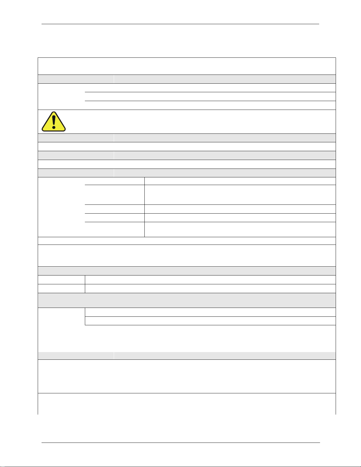
1.2. OPTIONS
Option
Option
Number
Description/Notes
Rack Mounting
For mounting the analyzer in standard 19” racks
20A
Rack mount brackets with 26 in. (660 mm) chassis slides
20B
Rack mount brackets with 24 in. (610 mm) chassis slides
21
Rack mount brackets only
The T703/T703U WEIGHS about 16.3 kg (36 pounds). To avoid personal injury we recommend
two persons lift and carry the calibrator.
Disconnect all cables and tubing from the calibrator before carrying it.
Carrying Handle
Strap to carry unit
29
Carrying handle (strap)
Parts Kits
Spare parts and expendables for 1-year operation
42A
Kit, Spares for One Unit
Communications
For remote serial, network and Internet communication with the analyzer.
Type
Description
Cables
60A
RS-232
Shielded, straight-through DB-9F to DB-25M cable, about 1.8 m long. Used to
interface with older computers or code activated switches with DB-25 serial
connectors.
60B
RS-232
Shielded, straight-through DB-9F to DB-9F cable of about 1.8 m length.
60C
Ethernet
Patch cable, 2 meters long, used for Internet and LAN communications.
60D
USB
Cable for direct connection between instrument (rear panel USB port) and
personal computer.
USB Port
64A
For rear panel connection to personal computer.
RS-232 Multidrop
62
Multidrop/LVDS card seated on the analyzer‟s CPU card.
Each instrument in the multidrop network requires this card and a communications cable
(Option 60B).
External Valve Driver Capability - For driving up to eight, 8-watt valves
48A
12V External Valve Driver Capability
48B
24V External Valve Driver Capability
NIST Traceable, Primary Standard Certification for use as a Primary Ozone Standard if purchased with the O3
generator and photometer options, 1A and 2A, respectively.
95C
Calibration to NIST-SRP
95D
Calibration as a Transfer Standard (6x6)
The Model T703 can be used as a Primary Ozone Standard. For this application the performance of the T703 Photometric
Calibrator is calibrated to Standard Reference Photometer (SRP) Calibrators ordered with this option are verified and
validated in accordance with the procedures prescribed by the U.S. Environmental Protection Agency (EPA) under Title 40
of the Code of Federal Regulations, Part 50, Appendix D (40 CFR Part 50).
Special Features
Built in features, software activated
N/A
Maintenance Mode Switch, located inside the instrument, places the analyzer in
maintenance mode where it can continue sampling, yet ignore calibration, diagnostic, and
reset instrument commands. This feature is of particular use for instruments connected to
Multidrop or Hessen protocol networks.
Call Technical Support for activation.
N/A
Second Language Switch activates an alternate set of display messages in a language
other than the instrument‟s default language.
Call Technical Support for a specially programmed Disk on Module containing the second language.
07223D DCN7107
17
2. SPECIFICATIONS AND APPROVALS
2.1. SPECIFICATIONS
Table 2-1: T703/T703U System Specifications
PARAMETER
SPECIFICATION
Linearity
±1.0% of full scale
Precision
1.0 ppb
Response Time
T703
T703U
<180 seconds to 95%
240 seconds to 95%
Stability (7-days)
<1% photometer feedback; <3% without photometer feedback (CNST or REF)
Operating Temperature Range
5-40ºC
Humidity Range
0 - 95% RH, non-condensing
Environmental Conditions
Installation Category (Over Voltage Category ) II
Pollution Degree 2
Intended for Indoor Use Only at Altitudes 2000m
Dimensions (H x W x D)
7” (178 mm) x 17” (432 mm) x 24” (609 mm)
Weight
35.5 lbs (16.1 kg) including internal zero air pump
AC Power
Rating
Typical Power Consumption
100V –120V, 60Hz, 3.0 A
220V –240V, 50/60Hz, 3.0 A
75 W (with Zero Air Pump 150 W)
95 W (with Zero Air Pump 170 W)
Analog Output Ranges
0.1 V, 1 V, 5 V or 10 V (selectable)
Range with 5% under/over-range
Standard I/O
1 Ethernet: 10/100Base-T
2 RS-232 (300 –115,200 baud)
2 USB device ports
8 opto-isolated digital control outputs
12 opto-isolated digital control inputs
8 opto-isolated digital status outputs
Optional I/O
1 USB com port
1 RS485
Multidrop RS232
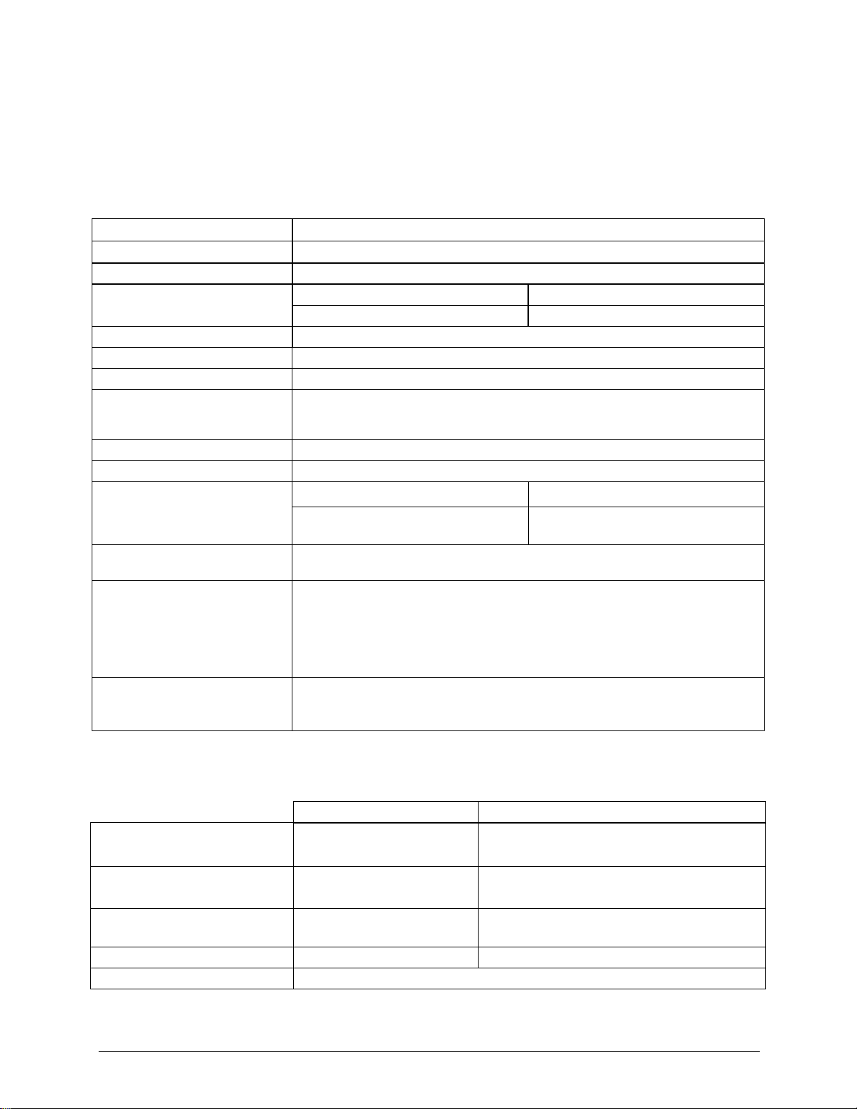
Table 2-2: T703/T703U Specifications for Ozone Generator
T703
T703U
Flow Rate
1 to 5 LPM adjustable
w/internal zero air source: 1 to 5 LPM adjustable
w/external zero air source: 1 to 15 LPM adjustable
Concentration
Min: 50 ppb at 2 LPM
Max: 5 ppm at 1 LPM
Min: 3 ppb at 5 LPM
Max: 5 ppm at 1 LPM
Output
Min: 100 ppb LPM
Max: 5 ppm LPM
Min: 15 ppb LPM
Max: 5 ppm LPM
Response Time:
<180 sec. to 98%
<240 sec. to 98%
Optical Feedback
Standard
07223D DCN7107

Specifications and Approvals Teledyne API T703/T703U Calibrator Operation Manual
18
Table 2-3: T703/T703U Specifications for O3Photometer
Ranges
0-100 ppb to 0-10 ppm, user selectable
Zero Noise
0.3ppb (RMS)
Span Noise
<0.5%
Lower Detectable Limits
0.6 ppb (RMS)
Precision
1.0 ppb
Linearity
1.0% of Full Scale
Lag Time
<10 seconds
Rise/Fall Time
<20 sec (photometer response)
Zero Drift
<1.0 ppb / 7 days
Span Drift
<1% / 24 hours; <2% / 7 days
Flow Rate
800 cc3/min +/- 10%
2.2. APPROVALS AND CERTIFICATIONS
The Teledyne API Models T703 and T703U Photometric O3Calibrators were
tested and certified for Safety and Electromagnetic Compatibility (EMC). This
section presents the compliance statements for those requirements and directives.
SAFETY2.2.1.
IEC 61010-1:2001, Safety requirements for electrical equipment for
measurement, control, and laboratory use.
CE: 2006/95/EC, Low-Voltage Directive
EMC2.2.2.
EN 61326-1 (IEC 61326-1), Class A Emissions/Industrial Immunity
EN 55011 (CISPR 11), Group 1, Class A Emissions
FCC 47 CFR Part 15B, Class A Emissions
CE: 2004/108/EC, Electromagnetic Compatibility Directive
OTHER TYPE CERTIFICATIONS2.2.3.
For additional certifications, please contact Technical Support:
Toll-free Phone:
800-324-5190
Phone:
858-657-9800
Fax:
858-657-9816
Email:
sda_techsupport @teledyne.com
07223D DCN7107
This manual suits for next models
1
Table of contents


