ATEQ D520 User manual

USER MANUAL
ATEQ D520
Version 1.32
Reference: UM-22100H-U


REVISION OF THE D520 USER MANUAL
Due to continuing improvements, the information contained in this user manual, the features and design
of this device are subject to be changed without prior notice.
Edition/
Revision Reference Date
(week/year) Chapters updated
First edition UM-22100A-U 22/2003 -----
Second edition UM-22100B-U 10/2004
A
ll chapters. Evolution of the programme
from the 1.00 to 1.10 version. Integration
of two capillaries. Addition of the "Single
CAL" and "No negative" functions, version
"High precision".
Third edition UM-22100C-U 41/2004
Evolution of the program version from the
1.10 to the 1.20. Add "High precision"
function, electronic regulator instruction
recover function and pressure filtering.
Fourth edition UM-22100D-U 08/2005 Evolution to the 1.21 version: gas version
(option).
Fifth edition UM-22100E-U 38/2009
Evolutions to the 1.32 version, add the
"Sequence" function, add bar code option
and add flow regulation function.
Sixth edition UM-22100F-U 47/2009
Preamble: add 1 l/h and 80 l/h capillary,
correction of the principle scheme for the
indirect measurement (recovery).
Seventh edition UM-22100H-U 02/2012
Chapter 4: modification of the sequences
management and up dating the bar code
function. H indices to be the same as the
French version.


Recommendations for leak testing
instruments
0039/Ret-U
Precautions for the test environment
•Keep the test area as clean as possible.
Precautions for the operators
•ATEQ recommends that the operators using the instruments should have a
suitable qualification and training with respect to the work bench requirements.
General precautions
•Read the user manual before using the instrument,
•all electrical connections to the instrument must be equipped with a safety
system (fuse, circuit breaker…) appropriate to its needs and complying with the
standards,
•to avoid electromagnetic interference, the cable connections to the instrument
should be less than two meters in length,
•it is essential that the electrical main is earthed,
•disconnect the electrical connections to the equipment before maintenance,
•cut the air supply for any kinds of operation on the pneumatic assembly,
•do not open the instrument when it is powered up,
•avoid water spillage near of the instrument,
•ATEQ is at your disposal for any further information concerning the use of the
instrument under maximum safety conditions.
We would like to bring to your attention that ATEQ will not be held responsible
for any accident connected to the improper use of the instrument, to the work
bench or to the lack of compliance with safety rules.
ATEQ Company is free from any responsibility for any adjustment of its
instrument which would not have been done by its own technicians.
The ATEQ cannot be held responsible if the instrument (program, mechanics or
electronics) has been modified without prior written consent.


SAV-Uc/0650
ATEQ, THE ASSURANCE OF A COMPETENT AFTER SALES
SERVICE
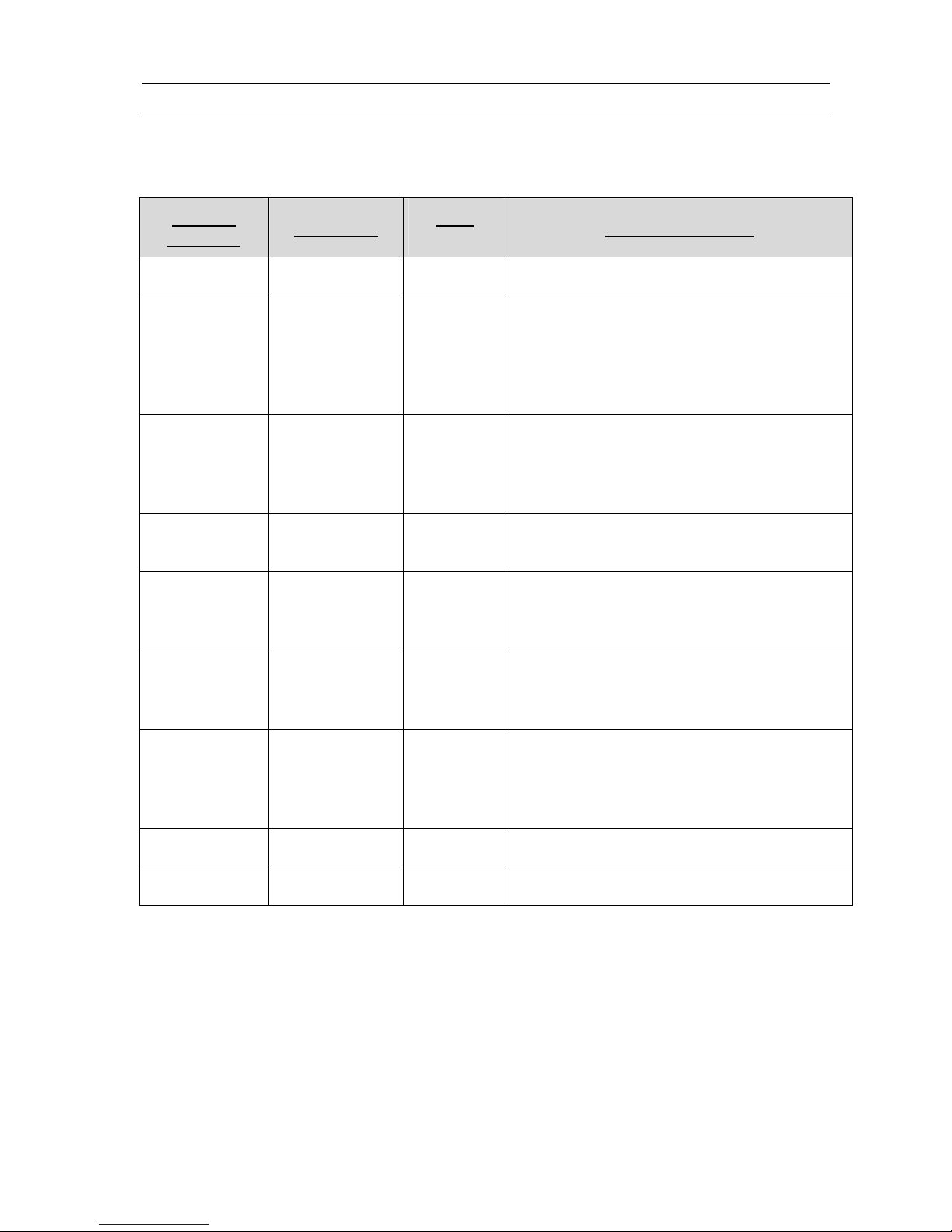
THE ATEQ AFTER SALES SERVICE IS :
•a team of qualified technicians,
•a permanent telephone assistance,
•agencies close to you for faster reaction,
•a stock of spare parts available immediately,
•a car fleet for rapid intervention,
•a commitment to quality ...
THE OVERHAUL
ATEQ carries out the overhaul of your instruments at interesting prices.
The overhaul corresponds to the maintenance of the instrument (checking, cleaning, replacing of used
parts) as part of preventive maintenance.
Preventive maintenance is the best way to guarantee reliability and efficiency. It allows the
maintenance of a group of instruments in good operational order and prevent eventual break-downs.
MAINTENANCE KITS
The ATEQ After Sales Service proposes, two kits destined for the preventive maintenance of the
pneumatic circuits of instruments.
CALIBRATION
This may be carried out on site or in our offices.
ATEQ is attached to the COFRAC and delivers a certificate following a calibration.
TRAINING COURSES
In the framework of partnership with our customers, ATEQ offers two types of training in order to
optimise the usage and knowledge of our instruments. They are aimed at different levels of technician:
•method / control training,
•maintenance / upkeep training.
A TARGETED TECHNICAL DOCUMENTATION
A number of technical documents are at your disposal to allow you to intervene rapidly in the event
minor breakdowns:
•problem sheets describing and offering solutions to the main pneumatic and electronic
problems,
•several maintenance manuals.
A QUALITY GUARANTEE
The instruments are guaranteed for parts and labour in our offices:
•2 years for leak detection equipment,
•1 year for electrical tests to norms instruments,
•1 year for the accessories.
Our After Sales Service is capable of rapidly answering all your needs and queries.
We strongly recommend to send the instrument
back to ATEQ once a year for re-calibration


0650/PREFd-U
PREFACE
Dear Customer,
You have just purchased an ATEQ instrument, we thank you for the trust you have
placed on our brand. This instrument has been designed to ensure a long and
unparalleled life expectancy, and we are convinced that it will give you complete
satisfaction during many long years of operation.
In order to maximise the life expectancy and reliability of your ATEQ instrument, we
recommend that you install this instrument on a secured workbench and advise you to
consult this manual in order to familiarise yourself with the functions and capabilities of
the instrument.
Our ATEQ After Sales Service centre can give you recommendations based on your
specific operation requirements.
ATEQ


Table of contents
UM-22100H-U User manual ATEQ D520 Page 1/122
TABLE OF CONTENTS
PREAMBLE 5
1. DEFINITION OF THE ATEQ D520 ......................................................................................................5
2. CHARACTERISTCS OF THE MEASUREMENT ................................................................................6
2.1. Pressure drop measurement........................................................................................................6
2.2. Test pressure measurement ........................................................................................................6
2.3. Mechanical pressure regulation ...................................................................................................6
3. THE DIFFERENT MEASUREMENT PRINCIPLES.............................................................................7
3.1. Direct measurement.....................................................................................................................7
3.2. Indirect measurement (or recovery mode)...................................................................................8
4. PRESSURE, TEMPERATURE & VISCOSITY EFFECT ON THE MEASUREMENT .........................9
4.1. Pressure variation ........................................................................................................................9
4.2. Viscosity and temperature variation.............................................................................................9
5. CALIBRATION...................................................................................................................................10
5.1. Factory calibration......................................................................................................................10
5.2. Manual calibration ......................................................................................................................10
6. PRINCIPLE OF A CYCLE .................................................................................................................11
7. PRESENTATION OF THE SYMBOLS ..............................................................................................12
Chapter 1 INSTALLATION OF THE INSTRUMENT
1. PRESENTATION OF THE ATEQ D520 ............................................................................................15
2. INSTALLATION OF THE INSTRUMENT ..........................................................................................16
2.1. Presentation of the connectors on the case of the D520...........................................................16
2.2. Connector details .......................................................................................................................17
Chapter 2 USER INTERFACES
1. PRESENTATION OF THE FRONT PANEL OF THE D520 ..............................................................27
2. PRESENTATION OF THE KEYBOARD KEYS ................................................................................28
2.1. Navigation keys..........................................................................................................................28
2.2. Cycle keys ..................................................................................................................................29
3. KEY LOCK.........................................................................................................................................29
4. REGULATOR.....................................................................................................................................30
5. INFRA-RED INTERFACE ..................................................................................................................30
6. 4 LINE LCD DISPLAY .......................................................................................................................30
7. QUICK CONNECTOR........................................................................................................................30
8. FUNCTIONNALITY OF THE INDICATORS ......................................................................................31
Chapter 3 STARTUP AND ADJUSTMENTS
1. POWERING UP THE ATEQ D520 ....................................................................................................33
2. CREATION OF A TEST PROGRAM.................................................................................................34
2.1. Choice of the program number ..................................................................................................34
2.2. Selection of the test type............................................................................................................35
2.3. Adjustment of the parameters ....................................................................................................36
3. COPYING A TEST PROGRAM .........................................................................................................40
4. DELETING A PROGRAM OR THE NAME OF A PROGRAM..........................................................42
5. LAUNCHING OF A CYCLE ...............................................................................................................43
5.1. Choice of the program number to be launched..........................................................................43
5.2. Setting the test pressure ............................................................................................................44
6. STARTING A MEASUREMENT CYCLE...........................................................................................45
7. STOPPING A CYCLE ........................................................................................................................45

Table of contents
UM-22100H-U User manual ATEQ D520 Page 2/122
Chapter 4 FUNCTIONS OF THE INSTRUMENT
1. MENU STRUCTURE..........................................................................................................................47
1.1. Main menu..................................................................................................................................47
1.2. "FUNCTIONS" menu when activated.........................................................................................52
2. CONFIGURATION MENU .................................................................................................................55
2.1. Extended menus ........................................................................................................................55
2.2. Automatic save...........................................................................................................................72
2.3. Program sequences ...................................................................................................................73
2.4. Ready status ..............................................................................................................................76
2.5. Reference cal .............................................................................................................................76
2.6. Bar Graph...................................................................................................................................76
2.7. Hour............................................................................................................................................77
2.8. Regulator learning......................................................................................................................77
2.9. RS232 ........................................................................................................................................78
2.10. RS485 ......................................................................................................................................81
2.11. Modbus.....................................................................................................................................81
2.12. Security ....................................................................................................................................81
2.13. Lighting the screen...................................................................................................................82
2.14. Bar code option ........................................................................................................................83
2.15. I/O configuration.......................................................................................................................86
2.16. Remote control.........................................................................................................................87
3. SPECIAL CYCLES MENU.................................................................................................................88
3.1. Special cycles available .............................................................................................................88
3.2. Regulator....................................................................................................................................89
3.3. Calculation of the automatic thresholds .....................................................................................90
3.4. Infinite fill ....................................................................................................................................91
3.5. Piezo reset (auto zero)...............................................................................................................92
3.6. Manual calibration ......................................................................................................................93
3.7. ATR learning ..............................................................................................................................96
4. SERVICE MENU ................................................................................................................................97
4.1. Servicing of the parameters .......................................................................................................97
4.2. Servicing of the sensors.............................................................................................................98
5. RESULTS MENU ...............................................................................................................................99
6. LANGUAGE MENU ...........................................................................................................................99
7. STAND-BY MENU .............................................................................................................................99
7.1. Standby using the menu ..........................................................................................................100
Chapter 5 ACCESSORIES
1. ACCESSORIES SUPPLIED WITH THE INSTRUMENT.................................................................101
1.1. Power supply............................................................................................................................101
2. OPTIONAL ACCESSORIES............................................................................................................102
2.1. Flow master leaks ....................................................................................................................102
2.2. Needle valve and leak flow calibrator ......................................................................................103
2.3. Automatic connectors with expandable joints ..........................................................................104
2.4. Filtration kit ...............................................................................................................................104
2.5. Remote controls .......................................................................................................................105
2.6. Remote front panel RC5 ..........................................................................................................106
2.7. Intelligent remote control..........................................................................................................108
2.8. External cutting valve ...............................................................................................................110
Chapter 6 ERROR MESSAGES
ERROR MESSAGES .................................................................................................. 111

Table of contents
UM-22100H-U User manual ATEQ D520 Page 3/122
Chapter 7 OPERATIONAL PROBLEMS
1. PHENOMENON NOTED..................................................................................................................113
1.1. Condition of the machine's seals .............................................................................................113
1.2. Damaged instrument seals ......................................................................................................113
1.3. Bumper pad..............................................................................................................................113
1.4. Pneumatic Link.........................................................................................................................113
1.5. Environment .............................................................................................................................114
1.6. Calibration ................................................................................................................................114
1.7. Concerns about reliability of the instrument’s circuits..............................................................114
Appendices ATEQ D520
1. TECHNICAL CHARACTERISTICS OF THE D520 .........................................................................115
2. DIMENSIONS OF THE D520...........................................................................................................116
3. CONVERSION TABLE ....................................................................................................................117
4. PARAMETERS SAVED...................................................................................................................118
5. VALVE CODES USED IN YOUR APPLICATION...........................................................................119
6. PERSONAL NOTES ........................................................................................................................120
Index 121

Table of contents
UM-22100H-U User manual ATEQ D520 Page 4/122

Preamble
UM-22100H-U User manual ATEQ D520 Page 5/122
PREAMBLE
1. DEFINITION OF THE ATEQ D520
The ATEQ D520 is a flow meter which measures a drop in pressure with a differential
sensor (transducer) which is placed at the extremities of a calibrated flow tube.
Test part
Air pressure
supply
Absolute pressure
sensor
Caloibrated flow tube
Regulator
Atmosphere
Differential
pressure sensor
Flow
Dp
When fluid (gas) moves through a calibrated flow tube (laminar flow), a drop in pressure
occurs, the value of which is proportional to flow.
∆P = 8µLQ/πR4
µ: viscosity of the fluid
L: length of the calibrated flow tube
R: radius of the calibrated flow tube
Q: flow
∆P: drop in pressure in the calibrated flow tube

Preamble
UM-22100H-U User manual ATEQ D520 Page 6/122
2. CHARACTERISTCS OF THE MEASUREMENT
2.1. PRESSURE DROP MEASUREMENT
RANGE L/H ACCURACY MAXIMUM
RESOLUTION L/H
1 +/- (2,5% of the flow + 0,001 l/h) 0,001
5 +/- (2,5% of the flow + 0,005 l/h) 0,001
30 +/- (2,5% of the flow + 0,03 l/h) 0,01
80 +/- (2,5% of the flow + 0,08 l/h) 0,01
150 +/- (2,5% of the flow + 0,150 l/h) 0,1
500 +/- (2,5% of the flow + 0,5 l/h) 0,1
1500 +/- (2,5% of the flow + 1,5 l/h) 1
4000 +/- (2,5% of the flow + 4 l/h) 1
10000 +/- (2,5% of the flow + 10 l/h) 1
(20° / 1013 mbar)
2.2. TEST PRESSURE MEASUREMENT
RANGE ACCURACY MAXIMUM
RESOLUTION
PE = 7.5 kPa
(PE < 75 mbar) +/- (1,5% of the pressure + 0,2 hPa)
PE < 30 kPa
(PE < 0,3 bar) +/- (1,5% of the pressure + 1 hPa)
30 kPa ≤PE ≤100 kPa
(0,3 bar ≤PE ≤1 bar) +/- (1,5% of the pressure + 3 hPa)
100 kPa < PE ≤500 kPa
(1 bar < PE ≤5 bar) +/- (1,5% of the pressure + 7.5 hPa)
0,1 % PE
2.3. MECHANICAL PRESSURE REGULATION
- 600 kPa to -10 kPa / 800 Pa to 6 kPa / 500 Pa to 14 kPa / 6 kPa to 100 kPa / 5 kPa to
210 kPa / 10 kPa to 350 kPa.

Preamble
UM-22100H-U User manual ATEQ D520 Page 7/122
3. THE DIFFERENT MEASUREMENT PRINCIPLES
There exists two measurement principles, they are: direct measurement and the indirect
measurement (also known as with recovery or under bell).
The instrument can work in depressurisation (optional) both in direct and indirect
measurement.
3.1. DIRECT MEASUREMENT
Test part
Air pressure
supply
Absolute
pressure
sensor
Calibrated flow tube
Regulator
Atmosphere
Differential
pressure sensor
Flow
Dp
As shown in the diagram above the test pressure is applied directly to the test part input
after having flowed through the calibrated flow tube.
Once the test part is filled, the ATEQ D520 measures the drop in pressure at the
extremities of the calibrated flow tube with a differential sensor.

Preamble
UM-22100H-U User manual ATEQ D520 Page 8/122
3.2. INDIRECT MEASUREMENT (OR RECOVERY MODE)
Test part
Air supply
Absolute
pressure
sensor Calibrated flow tube
Regulator
Atmosphere
Differential
pressure sensor
Flow
Dp
The calibrated flow tube is placed following the output of the test part. The output of the
calibrated flow tube is to the atmosphere.
Depending on the part type, it may be possible to use a bell (ex: shower head where it
is impossible to recover the flow other than through the use of a bell). This method can
only be used if the recovery of the flow is easy.
The indirect measurement allows a considerable gain in time as the flow which arrives
in the calibrated flow tube is already stabilised.

Preamble
UM-22100H-U User manual ATEQ D520 Page 9/122
4. PRESSURE, TEMPERATURE & VISCOSITY EFFECT ON THE MEASUREMENT
4.1. PRESSURE VARIATION
As shown in the direct measurement diagram, the test part is in series in the test circuit,
the test pressure set by the regulator is not entirely restored at the input of the test part
due to pressure losses caused by the calibrated flow tube. Additionally the output
pressure of the regulator changes depending on the flows.
The results are always expressed as a function of the test pressure. That is why a
silicium sensor constantly monitors the real test pressure applied to the part. Depending
on the pressure value read the ATEQ D520 applies a correction factor which allows a
constant compensation for the pressure drops in the test circuit.
Note that the further the test part is from the cell, the higher the pressure drop is. This
should be avoided (possibility of pressure measurement on the part).
4.2. VISCOSITY AND TEMPERATURE VARIATION
The viscosity of a gas is directly linked to its temperature. The higher the temperature is,
the greater the viscosity. The law of “Poiseuille” shows that when the viscosity
increases, the pressure drop increases.
These two parameters, temperature and viscosity have an influence on the accuracy of
the measurement. A correction is applied depending on the real temperature of the gas
flowing through the system.
Variations in the temperature of the parts during the test and in relation to each other
should be avoided by the "High precision" mode (optional):
An automatic acquisition cycle on a known master value is realised before each test
cycle, it allows calculating the test part value with the current atmospherics conditions.

Preamble
UM-22100H-U User manual ATEQ D520 Page 10/122
5. CALIBRATION
There exist 2 different types of calibration.
5.1. FACTORY CALIBRATION
The factory calibration is set in the instrument.
Display
Calibrated flow
tube
1000
1000 l/h
Master leak
1000 l/h
Note: this calibration does not take into account tube lengths, seal jig restrictions, ...
5.2. MANUAL CALIBRATION
It is possible that the unit the instrument is delivered in or some external elements
(seals, pipes...) result in the factory calibration being unsatisfactory.
In this case a manual calibration taking into account the previously stated elements, can
be carried out by the operator. For this calibration, the calibrated master leak should be
used in the same conditions as the parts to be measured (diameter, length of the pipes).
Table of contents
Other ATEQ Test Equipment manuals

ATEQ
ATEQ ADSE 550 User manual

ATEQ
ATEQ F600 User manual

ATEQ
ATEQ F610 Instruction manual

ATEQ
ATEQ PRIMUS F Series User manual

ATEQ
ATEQ F28+ User manual

ATEQ
ATEQ F670 User manual

ATEQ
ATEQ F6 Profinet Series User manual

ATEQ
ATEQ F600HP User manual

ATEQ
ATEQ F5800 Instruction manual

ATEQ
ATEQ Hydra Silver Owner's manual