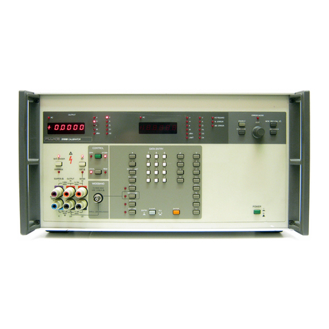
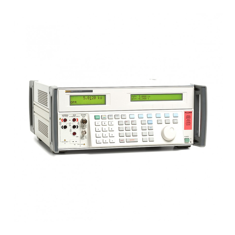
Fluke 5500A User manual

®
5500A
Multi-Product Calibrator
Service Manual
PN 105798
August 1995 Rev.5, 4/03
© 1995-2003 Fluke Corporation. All rights reserved. Printed in U.S.A.
All product names are trademarks of their respective companies.

LIMITED WARRANTY & LIMITATION OF LIABILITY
Each Fluke product is warranted to be free from defects in material and workmanship under
normal use and service. The warranty period is one year and begins on the date of shipment.
Parts, product repairs and services are warranted for 90 days. This warranty extends only to the
original buyer or end-user customer of a Fluke authorized reseller, and does not apply to fuses,
disposable batteries or to any product which, in Fluke’s opinion, has been misused, altered,
neglected or damaged by accident or abnormal conditions of operation or handling. Fluke
warrants that software will operate substantially in accordance with its functional specifications for
90 days and that it has been properly recorded on non-defective media. Fluke does not warrant
that software will be error free or operate without interruption.
Fluke authorized resellers shall extend this warranty on new and unused products to end-user
customers only but have no authority to extend a greater or different warranty on behalf of Fluke.
Warranty support is available if product is purchased through a Fluke authorized sales outlet or
Buyer has paid the applicable international price. Fluke reserves the right to invoice Buyer for
importation costs of repair/replacement parts when product purchased in one country is submitted
for repair in another country.
Fluke’s warranty obligation is limited, at Fluke’s option, to refund of the purchase price, free of
charge repair, or replacement of a defective product which is returned to a Fluke authorized
service center within the warranty period.
To obtain warranty service, contact your nearest Fluke authorized service center or send the
product, with a description of the difficulty, postage and insurance prepaid (FOB Destination), to
the nearest Fluke authorized service center. Fluke assumes no risk for damage in transit.
Following warranty repair, the product will be returned to Buyer, transportation prepaid (FOB
Destination). If Fluke determines that the failure was caused by misuse, alteration, accident or
abnormal condition of operation or handling, Fluke will provide an estimate of repair costs and
obtain authorization before commencing the work. Following repair, the product will be returned to
the Buyer transportation prepaid and the Buyer will be billed for the repair and return
transportation charges (FOB Shipping Point).
THIS WARRANTY IS BUYER’S SOLE AND EXCLUSIVE REMEDY AND IS IN LIEU OF ALL
OTHER WARRANTIES, EXPRESS OR IMPLIED, INCLUDING BUT NOT LIMITED TO ANY
IMPLIED WARRANTY OF MERCHANTABILITY OR FITNESS FOR A PARTICULAR PURPOSE.
FLUKE SHALL NOT BE LIABLE FOR ANY SPECIAL, INDIRECT, INCIDENTAL OR
CONSEQUENTIAL DAMAGES OR LOSSES, INCLUDING LOSS OF DATA, WHETHER
ARISING FROM BREACH OF WARRANTY OR BASED ON CONTRACT, TORT, RELIANCE OR
ANY OTHER THEORY.
Since some countries or states do not allow limitation of the term of an implied warranty, or
exclusion or limitation of incidental or consequential damages, the limitations and exclusions of
this warranty may not apply to every buyer. If any provision of this Warranty is held invalid or
unenforceable by a court of competent jurisdiction, such holding will not affect the validity or
enforceability of any other provision.
Fluke Corporation Fluke Europe B.V.
P.O. Box 9090 P.O. Box 1186
Everett, WA 98206-9090 5602 BD Eindhoven
U.S.A. The Netherlands
5/94

i
Table of Contents
Chapter Title Page
1 Introduction and Specifications........................................................ 1-1
1-1. Introduction........................................................................................... 1-3
1-2. Service Information .............................................................................. 1-4
1-3. Specifications........................................................................................ 1-4
1-4. General Specifications...................................................................... 1-6
1-5. DC Voltage Specifications............................................................... 1-7
1-6. DC Current Specifications ............................................................... 1-8
1-7. Resistance Specifications................................................................. 1-9
1-8. AC Voltage (Sinewave) Specifications............................................ 1-10
1-9. AC Current (Sinewave) Specifications............................................ 1-13
1-10. Capacitance Specifications............................................................... 1-15
1-11. Temperatore Calibration (Thermocouple) Specifications................ 1-16
1-12. Temperature Calibration (RTD) Specifications............................... 1-17
1-13. DC Power Specification Summary................................................... 1-19
1-14. AC Power (45 Hz to 65 Hz) Specification Summary, PF=1............ 1-20
1-15. Power and Dual Output Limit Specifications .................................. 1-21
1-16. 5500A Phase Specifications............................................................. 1-21
1-17. Calculating Power Uncertainty ........................................................ 1-23
1-18. Additional Specifications ..................................................................... 1-24
1-19. Frequency Specifications ................................................................. 1-24
1-20. Harmonics (2nd to 50th) Specifications........................................... 1-25
1-21. AC Voltage (Sinewave) Extended Bandwidth Specifications......... 1-26
1-22. AC Voltage (Non-Sinewave) Specifications.................................... 1-27
1-23. AC Voltage, DC Offset Specifications ............................................ 1-28
1-24. AC Voltage, Squarewave Characteristics ........................................ 1-29
1-25. AC Voltage, Trianglewave Characteristics (typical) ....................... 1-29
1-26. AC Current (Sinewave) Extended Bandwidth Specifications.......... 1-29
1-27. AC Current (Non-Sinewave) Specifications.................................... 1-30
1-28. AC Current, Squarewave Characteristics (typical).......................... 1-31
1-29. AC Current, Trianglewave Characteristics (typical)........................ 1-31
2 Theory of Operation........................................................................... 2-1
2-1. Introduction........................................................................................... 2-3
2-2. Encoder Assembly (A2)........................................................................ 2-4

5500A
Service Manual
ii
2-3. Synthesized Impedance Assembly (A5)............................................... 2-4
2-4. DDS Assembly (A6)............................................................................. 2-5
2-5. Current Assembly (A7)......................................................................... 2-6
2-6. Voltage Assembly (A8)........................................................................ 2-7
2-7. Main CPU Assembly (A9).................................................................... 2-8
2-8. Power Supplies ..................................................................................... 2-8
2-9. Outguard Supplies............................................................................ 2-8
2-10. Inguard Supplies............................................................................... 2-8
3 Calibration and Verification............................................................... 3-1
3-1. Introduction........................................................................................... 3-3
3-2. Calibration ............................................................................................ 3-3
3-3. Equipment Required for Calibration and Verification..................... 3-3
3-4. Starting Calibration .......................................................................... 3-4
3-5. How the Calibration Procedure Works ............................................ 3-4
3-6. DC Volts........................................................................................... 3-5
3-7. AC Volts........................................................................................... 3-5
3-8. Thermocouple Measuring................................................................. 3-6
3-9. DC Current ....................................................................................... 3-7
3-10. AC Current ....................................................................................... 3-8
3-11. AUX DC Volts................................................................................. 3-8
3-12. AUX AC Volts................................................................................. 3-9
3-13. Resistance......................................................................................... 3-9
3-14. Capacitance ...................................................................................... 3-12
3-15. Capacitance, Four-Wire Comp......................................................... 3-14
3-16. Frequency......................................................................................... 3-14
3-17. NORMAL Volts and AUX Volts Phase........................................... 3-15
3-18. Volts and AUX Current Phase ......................................................... 3-15
3-19. Remote Commands for 5500A Calibration...................................... 3-16
3-20. Generating a Calibration Report........................................................... 3-18
3-21. Calibration Shifts Report, Printout Format...................................... 3-18
3-22. Calibration Shifts Report, Spreadsheet Format................................ 3-19
3-23. Calibration Constant Report, Printout Format................................. 3-19
3-24. Calibration Constants Report, Spreadsheet Format......................... 3-20
3-25. Performance Verification Tests............................................................ 3-20
3-26. Zeroing the Calibrator...................................................................... 3-20
3-27. DC Voltage Amplitude Accuracy (NORMAL) ............................... 3-21
3-28. DC Voltage Amplitude Accuracy (AUX)........................................ 3-21
3-29. DC Current Amplitude Accuracy..................................................... 3-22
3-30. Resistance Accuracy......................................................................... 3-23
3-31. Resistance DC Offset Measurement................................................. 3-24
3-32. AC Voltage Amplitude Accuracy (NORMAL) ............................... 3-25
3-33. AC Voltage Amplitude Accuracy (AUX)........................................ 3-27
3-34. AC Current Amplitude Accuracy..................................................... 3-28
3-35. Capacitance Accuracy...................................................................... 3-29
3-36. Thermocouple Measurement Accuracy............................................ 3-31
3-37. Thermocouple Sourcing Accuracy................................................... 3-31
3-38. Thermocouple Measuring Accuracy................................................ 3-31
3-39. DC Power Amplitude Accuracy (NORMAL).................................. 3-32
3-40. DC Power Amplitude Accuracy (AUX)........................................... 3-32
3-41. AC Power Amplitude Accuracy (High Voltage).............................. 3-33
3-42. AC Power Amplitude Accuracy (High Current).............................. 3-33
3-43. AC Power Amplitude Accuracy (High Power)................................ 3-34
3-44. Phase and Frequency Accuracy........................................................ 3-34

Contents
(continued)
iii
3-45. AC Voltage Amplitude Accuracy, Squarewave (NORMAL).......... 3-36
3-46. AC Voltage Amplitude Accuracy, Squarewave (AUX)................... 3-37
3-47. AC Voltage Harmonic Amplitude Accuracy (NORMAL)............... 3-38
3-48. AC Voltage Harmonic Amplitude Accuracy (AUX)....................... 3-39
3-49. DC Voltage Offset Accuracy ........................................................... 3-39
3-50. AC Voltage Accuracy with a DC Offset.......................................... 3-40
4 Maintenance........................................................................................ 4-1
4-1. Introduction........................................................................................... 4-3
4-2. Access Procedures................................................................................ 4-3
4-3. Removing Analog Modules.............................................................. 4-3
4-4. Removing the Main CPU (A9)......................................................... 4-3
4-5. Removing Rear Panel Assemblies.................................................... 4-4
4-6. Removing the Filter PCA (A12)....................................................... 4-4
4-7. Removing the Encoder (A2) and Display PCAs.............................. 4-4
4-8. Removing the Keyboard and Accessing the Output Block.............. 4-4
4-9. Diagnostic Testing................................................................................ 4-7
4-10. Running Diagnostics ........................................................................ 4-7
4-11. Sequence of Diagnostics Tests..................................................... 4-7
4-12. Diagnostics Error Messages......................................................... 4-7
4-13. Testing the Front Panel .................................................................... 4-13
4-14. Internal Fuse Replacement.................................................................... 4-14
4-15. Complete List of Error Messages......................................................... 4-14
5 List of Replaceable Parts................................................................... 5-1
5-1. Introduction........................................................................................... 5-3
5-2. How to Obtain Parts.............................................................................. 5-3
5-3. How to Contact Fluke........................................................................... 5-3
5-4. Parts Lists.............................................................................................. 5-4
6 Oscilloscope Calibration Options..................................................... 6-1
SC600 Option...................................................................................... 6-3
6-1. Introduction........................................................................................... 6-5
6-2. Maintenance.......................................................................................... 6-5
6-3. SC600 Specifications............................................................................ 6-6
6-4. Volt Specifications........................................................................... 6-6
6-5. Edge Specifications.......................................................................... 6-7
6-6. Leveled Sine Wave Specifications................................................... 6-8
6-7. Time Marker Specifications............................................................. 6-9
6-8. Wave Generator Specifications........................................................ 6-9
6-9. Pulse Generator Specifications......................................................... 6-10
6-10. Trigger Signal Specifications (Pulse Function) ............................... 6-10
6-11. Trigger Signal Specifications (Time Marker Function)................... 6-10
6-12. Trigger Signal Specifications (Edge Function)................................ 6-11
6-13. Trigger Signal Specifications (Square Wave Voltage Function)..... 6-11
6-14. Trigger Signal Specifications........................................................... 6-11
6-15. Oscilloscope Input Resistance Measurement Specifications........... 6-11
6-16. Oscilloscope Input Capacitance Measurement Specifications......... 6-11
6-17. Overload Measurement Specifications............................................. 6-12
6-18. Theory of Operation ............................................................................. 6-12
6-19. Voltage Mode................................................................................... 6-12
6-20. Edge Mode........................................................................................ 6-12

5500A
Service Manual
iv
6-21. Leveled Sine Wave Mode ................................................................ 6-12
6-22. Time Marker Mode .......................................................................... 6-13
6-23. Wave Generator Mode ..................................................................... 6-13
6-24. Input Impedance Mode (Resistance)................................................ 6-13
6-25. Input Impedance Mode (Capacitance).............................................. 6-13
6-26. Overload Mode................................................................................. 6-13
6-27. Equipment Required for Calibration and Verification......................... 6-15
6-28. SC600 Calibration Setup ...................................................................... 6-17
6-29. Calibration and Verification of Square Wave Voltage Functions........ 6-18
6-30. Overview of HP3458A Operation.................................................... 6-18
6-31. Setup for SC600 Voltage Square Wave Measurements................... 6-18
6-32. Setup for SC600 Edge and Wave Gen Square Wave Measurements 6-20
6-33. DC Voltage Calibration.................................................................... 6-21
6-34. AC Voltage Calibration.................................................................... 6-21
6-35. Wave Generator Calibration............................................................. 6-22
6-36. Edge Amplitude Calibration............................................................. 6-22
6-37. Leveled Sine Wave Amplitude Calibration...................................... 6-23
6-38. Leveled Sine Wave Flatness Calibration ......................................... 6-24
6-39. Low Frequency Calibration ......................................................... 6-24
6-40. High Frequency Calibration......................................................... 6-25
6-41. Pulse Width Calibration................................................................... 6-25
6-42. MeasZ Calibration............................................................................ 6-26
6-43. Verification........................................................................................... 6-28
6-44. DC Voltage Verification .................................................................. 6-29
6-45. Verification at 1 MΩ.................................................................... 6-29
6-46. Verification at 50 Ω..................................................................... 6-29
6-47. AC Voltage Amplitude Verification ................................................ 6-31
6-48. Verification at 1 MΩ.................................................................... 6-31
6-49. Verification at 50 Ω..................................................................... 6-33
6-50. AC Voltage Frequency Verification ................................................ 6-34
6-51. Edge Amplitude Verification ........................................................... 6-35
6-52. Edge Frequency Verification............................................................ 6-35
6-53. Edge Duty Cycle Verification.......................................................... 6-36
6-54. Edge Rise Time Verification............................................................ 6-36
6-55. Edge Abberation Verification .......................................................... 6-38
6-56. Tunnel Diode Pulser Drive Amplitude Verification........................ 6-39
6-57. Leveled Sine Wave Amplitude Verification.................................... 6-40
6-58. Leveled Sine Wave Frequency Verification .................................... 6-41
6-59. Leveled Sine Wave Harmonics Verification.................................... 6-42
6-60. Leveled Sine Wave Flatness Verification........................................ 6-44
6-61. Equipment Setup for Low Frequency Flatness............................ 6-44
6-62. Equipment Setup for High Frequency Flatness ........................... 6-44
6-63. Low Frequency Verification........................................................ 6-46
6-64. High Frequency Verification ....................................................... 6-46
6-65. Time Marker Verification ................................................................ 6-51
6-66. Wave Generator Verification........................................................... 6-52
6-67. Verification at 1 MΩ.................................................................... 6-52
6-68. Verification at 50 Ω..................................................................... 6-53
6-69. Pulse Width Verification.................................................................. 6-56
6-70. Pulse Period Verification ................................................................. 6-57
6-71. MeasZ Resistance Verification ........................................................ 6-57
6-72. MeasZ Capacitance Verification...................................................... 6-58
6-73. Overload Function Verification ....................................................... 6-59
6-74. SC600 Hardware Adjustments ............................................................. 6-60
6-75. Equipment Required......................................................................... 6-60

Contents
(continued)
v
6-76. Adjusting the Leveled Sine Wave Function..................................... 6-60
6-77. Equipment Setup.......................................................................... 6-61
6-78. Adjusting the Leveled Sine Wave VCO Balance ........................ 6-61
6-79. Adjusting the Leveled Sine Wave Harmonics............................. 6-62
6-80. Adjusting the Aberrations for the Edge Function ............................ 6-62
6-81. Equipment Setup.......................................................................... 6-63
6-82. Adjusting the Edge Aberrations................................................... 6-63
SC300 Option...................................................................................... 6-65
6-83. Introduction........................................................................................... 6-67
6-84. Maintenance.......................................................................................... 6-67
6-85. SC300 Specifications............................................................................ 6-68
6-86. Voltage Function Specifications ...................................................... 6-68
6-87. Edge Function Specifications........................................................... 6-69
6-88. Leveled Sine Wave Function Specifications.................................... 6-70
6-89. Time Marker Function Specifications.............................................. 6-71
6-90. Wave Generator Specifications........................................................ 6-71
6-91. Trigger Signal Specifications for the Time Marker Function.......... 6-72
6-92. Trigger Signal Specifications for the Edge Function....................... 6-72
6-93. Theory of Operation ............................................................................. 6-72
6-94. Voltage Mode................................................................................... 6-72
6-95. Edge Mode........................................................................................ 6-72
6-96. Leveled Sine Wave Mode ................................................................ 6-72
6-97. Time Marker Mode .......................................................................... 6-72
6-98. Wave Generator Mode ..................................................................... 6-73
6-99. Equipment Required for Calibration and Verification......................... 6-75
6-100. SC300 Calibration Setup ...................................................................... 6-77
6-101. Calibration and Verification of Square Wave Functions ..................... 6-78
6-102. Overview of HP3458A Operation.................................................... 6-78
6-103. Setup for Square Wave Measurements ............................................ 6-78
6-104. DC Voltage Calibration.................................................................... 6-79
6-105. AC Square Wave Voltage Calibration............................................. 6-80
6-106. Edge Amplitude Calibration............................................................. 6-81
6-107. Leveled Sine Wave Amplitude Calibration...................................... 6-81
6-108. Leveled Sine Wave Flatness Calibration ......................................... 6-82
6-109. Low Frequency Calibration ......................................................... 6-83
6-110. High Frequency Calibration......................................................... 6-83
6-111. Verification........................................................................................... 6-84
6-112. DC Voltage Verification .................................................................. 6-84
6-113. Verification at 1 MΩ.................................................................... 6-84
6-114. Verification at 50 Ω..................................................................... 6-84
6-115. AC Voltage Amplitude Verification ................................................ 6-87
6-116. Verification at 1 MΩ.................................................................... 6-87
6-117. Verification at 50 Ω..................................................................... 6-89
6-118. AC Voltage Frequency Verification ................................................ 6-90
6-119. Edge Amplitude Verification ........................................................... 6-91
6-120. Edge Frequency Verification............................................................ 6-92
6-121. Edge Duty Cycle Verification.......................................................... 6-93
6-122. Edge Rise Time Verification............................................................ 6-93
6-123. Edge Abberation Verification .......................................................... 6-95
6-124. Leveled Sine Wave Reference Verification..................................... 6-96
6-125. Leveled Sine Wave Frequency Verification .................................... 6-97
6-126. Leveled Sine Wave Harmonics Verification.................................... 6-98
6-127. Leveled Sine Wave Flatness Verification........................................ 6-100

5500A
Service Manual
vi
6-128. Equipment Setup for Low Frequency Flatness............................ 6-100
6-129. Equipment Setup for High Frequency Flatness ........................... 6-100
6-130. Low Frequency Verification........................................................ 6-102
6-131. High Frequency Verification ....................................................... 6-102
6-132. Time Marker Verification ................................................................ 6-107
6-133. Wave Generator Verification........................................................... 6-108
6-134. Verification at 1 MΩ.................................................................... 6-109
6-135. Verification at 50 Ω..................................................................... 6-109
6-136. SC300 Hardware Adjustments ............................................................. 6-111
6-137. Equipment Required......................................................................... 6-112
6-138. Adjusting the Leveled Sine Wave Function..................................... 6-112
6-139. Equipment Setup.......................................................................... 6-112
6-140. Adjusting the Leveled Sine Wave Harmonics............................. 6-112
6-141. Adjusting the Aberrations for the Edge Function ............................ 6-113
6-142. Equipment Setup.......................................................................... 6-113
6-143. Adjusting the Edge Aberrations................................................... 6-113
6-144. SC300 Hardware Adjustments for the A4 Board................................. 6-115
6-145. Equipment Required......................................................................... 6-115
6-146. Adjusting the Leveled Sine Wave Function..................................... 6-115
6-147. Equipment Setup.......................................................................... 6-115
6-148. Adjusting the Leveled Sine Wave VCO Balance ........................ 6-115
6-149. Adjusting the Leveled Sine Wave Harmonics............................. 6-116
6-150. Adjusting the Aberrations for the Edge Function ............................ 6-117
6-151. Equipment Setup.......................................................................... 6-117
6-152. Adjusting the Edge Aberrations for Board 5500A-4004-1.......... 6-118
6-153. Adjusting the Edge Aberrations for Board 5500A-4004............. 6-120
6-154. Adjusting the Rise Time for the Edge Function............................... 6-122
6-155. Equipment Setup.......................................................................... 6-122
6-156. Adjusting the Edge Rise Time..................................................... 6-122
Index

vii
List of Tables
Table Title Page
3-1. Required Equipment for Calibration and Verification........................................... 3-4
3-2. DC Volts Calibration Steps.................................................................................... 3-5
3-3. AC Volts Calibration Steps.................................................................................... 3-5
3-4. DC Current Calibration Steps................................................................................ 3-7
3-5. AC Current Calibration Steps................................................................................ 3-8
3-6. AUX DCVolts Calibration Steps........................................................................... 3-8
3-7. AUX ACVolts Calibration Steps........................................................................... 3-9
3-8. Resistance Calibration Steps.................................................................................. 3-10
3-9. Capacitance Calibration Steps ............................................................................... 3-13
3-10. Normal Volts and AUX Volts Phase Calibration Steps......................................... 3-15
3-11. Volts and Current Phase Calibration Steps............................................................ 3-16
3-12. Jumping to a Specific Calibration Step.................................................................. 3-17
3-13. DC Voltage Performance Test............................................................................... 3-21
3-14. AC Voltage Performance Test............................................................................... 3-21
3-15. DC Current Amplitude Accuracy Test................................................................... 3-22
3-16. Resistance Accuracy Test ...................................................................................... 3-23
3-17. Resistance DC Offset Measurement Test .............................................................. 3-24
3-18. AC Voltage Amplitude Accuracy Test (NORMAL) ............................................. 3-25
3-19. AC Voltage Amplitude Accuracy Test (AUX)...................................................... 3-27
3-20. AC Current Amplitude Accuracy Test................................................................... 3-28
3-21. Capacitance Accuracy Test.................................................................................... 3-30
3-22. Thermocouple Measurement Accuracy Test ......................................................... 3-31
3-23. Thermocouple Sourcing Accuracy Test................................................................. 3-31
3-24. Thermocouple Measuring Accuracy Test.............................................................. 3-32
3-25. DC Power Amplitude Accuracy Test (NORMAL)................................................ 3-32
3-26. DC Power Amplitude Accuracy Test (AUX) ........................................................ 3-32
3-27. AC Power Amplitude Accuracy Test (High Voltage) ........................................... 3-33
3-28. AC Power Amplitude Accuracy Test (High Current)............................................ 3-33
3-29. AC Power Amplitude Accuracy Test (High Power).............................................. 3-34
3-30. Phase Accuracy Test .............................................................................................. 3-34
3-31. Frequency Accuracy Test....................................................................................... 3-35
3-32. AC Voltage Amplitude Accuracy, Squarewave (NORMAL)................................ 3-36
3-33. AC Voltage Amplitude Accuracy, Squarewave (AUX) ........................................ 3-37
3-34. AC Voltage Harmonic Amplitude Accuracy (NORMAL).................................... 3-38
3-35. AC Voltage Harmonic Amplitude Accuracy (AUX)............................................. 3-39
3-36. DC Voltage Offset Accuracy Test ......................................................................... 3-39

5500A
Service Manual
viii
3-37. AC Voltage Accuracy with a DC Offset................................................................ 3-40
4-1. Internal Fuse Locations.......................................................................................... 4-14
4-2. Error Message Format............................................................................................ 4-14
5-1. Chassis Assembly................................................................................................... 5-5
5-2. Front Panel Assembly............................................................................................ 5-8
5-3. Rear Panel Assembly ............................................................................................. 5-10
6-1. Volt Specifications................................................................................................. 6-6
6-2. Edge Specifications................................................................................................ 6-7
6-3. Leveled Sine Wave Specifications......................................................................... 6-8
6-4. Time Marker Specifications................................................................................... 6-9
6-5. Wave Generator Specifications.............................................................................. 6-9
6-6. Pulse Generator Specifications .............................................................................. 6-10
6-7. Trigger Signal Specifications (Pulse Function)..................................................... 6-10
6-8. Trigger Signal Specifications (Time Marker Function)......................................... 6-10
6-9. Trigger Signal Specifications (Edge Function)...................................................... 6-11
6-10. Trigger Signal Specifications (Square Wave Voltage Function)........................... 6-11
6-11. TV Trigger Signal Specifications .......................................................................... 6-11
6-12. Oscilloscope Input Resistance Measurement Specifications................................. 6-11
6-13. Oscilloscope Input Capacitance Measurement Specifications .............................. 6-11
6-14. Overload Measurement Specifications .................................................................. 6-12
6-15. SC600 Calibration and Verification Equipment.................................................... 6-15
6-16. Voltage HP3458A Settings.................................................................................... 6-19
6-17. Edge and Wave Generator HP3458A Settings....................................................... 6-20
6-18. Verification Methods for SC600 Functions........................................................... 6-28
6-19. DC Voltage Verification at 1 MΩ......................................................................... 6-30
6-20. DC Voltage Verification at 50 Ω........................................................................... 6-31
6-21. AC Voltage Verification at 1 MΩ......................................................................... 6-32
6-22. AC Voltage Verification at 50 Ω........................................................................... 6-33
6-23. AC Voltage Frequency Verification...................................................................... 6-34
6-24. Edge Amplification Verification............................................................................ 6-35
6-25. Edge Frequency Verification ................................................................................. 6-36
6-26. Edge Rise Time Verification.................................................................................. 6-38
6-27. Edge Aberrations.................................................................................................... 6-39
6-28. Tunnel Diode Pulser Amplitude Verification........................................................ 6-39
6-29. Leveled Sine Wave Amplitude Verification.......................................................... 6-40
6-30. Leveled Sine Wave Frequency Verification.......................................................... 6-41
6-31. Leveled Sine Wave Harmonics Verification ......................................................... 6-43
6-32. Low Frequency Flatness Verification at 5.5 V...................................................... 6-46
6-33. High Frequency Flatness Verification at 5.5 V ..................................................... 6-47
6-34. High Frequency Flatness Verification at 7.5 mV .................................................. 6-48
6-35. High Frequency Flatness Verification at 25 mV ................................................... 6-48
6-36. High Frequency Flatness Verification at 70 mV ................................................... 6-49
6-37. High Frequency Flatness Verification at 250 mV ................................................. 6-49
6-38. High Frequency Flatness Verification at 800 mV ................................................. 6-50
6-39. High Frequency Flatness Verification at 3.4 V ..................................................... 6-50
6-40. Time Marker Verification...................................................................................... 6-51
6-41. Wave Generator Verification at 1 MΩ.................................................................. 6-54
6-42. Wave Generator Verification at 50 Ω.................................................................... 6-55
6-43. Pulse Width Verification........................................................................................ 6-56
6-44. Pulse Period Verification....................................................................................... 6-57
6-45. MeasZ Resistance Verification.............................................................................. 6-58
6-46. MeasZ Capacitance Verification............................................................................ 6-59
6-47. SC300 Calibration and Verification Equipment.................................................... 6-75
6-48. AC Square Wave Voltage and Edge Settings for the HP3458A............................ 6-78
6-49. DC Voltage Verification at 1 MΩ......................................................................... 6-85

Contents
(continued)
ix
6-50. DC Voltage Verification at 50 Ω........................................................................... 6-86
6-51. AC Voltage Verification at 1 MΩ......................................................................... 6-88
6-52. AC Voltage Verification at 50 Ω........................................................................... 6-89
6-53. AC Voltage Frequency Verification...................................................................... 6-91
6-54. Edge Amplification Verification............................................................................ 6-92
6-55. Edge Frequency Verification ................................................................................. 6-92
6-56. Edge Rise Time Verification.................................................................................. 6-95
6-57. Edge Aberrations.................................................................................................... 6-96
6-58. Leveled Sine Wave Amplitude Verification.......................................................... 6-97
6-59. Leveled Sine Wave Frequency Verification.......................................................... 6-98
6-60. Leveled Sine Wave Harmonics Verification ......................................................... 6-99
6-61. Low Frequency Flatness Verification at 5.5 V...................................................... 6-102
6-62. High Frequency Flatness Verification at 5.5 V ..................................................... 6-103
6-63. High Frequency Flatness Verification at 7.5 mV .................................................. 6-104
6-64. High Frequency Flatness Verification at 25 mV ................................................... 6-104
6-65. High Frequency Flatness Verification at 70 mV ................................................... 6-105
6-66. High Frequency Flatness Verification at 250 mV ................................................. 6-105
6-67. High Frequency Flatness Verification at 800 mV ................................................. 6-106
6-68. High Frequency Flatness Verification at 3.4 V ..................................................... 6-106
6-69. Time Marker Specifications................................................................................... 6-108
6-70. Wave Generator Verification at 1 MΩ.................................................................. 6-110
6-71. Wave Generator Verification at 50 Ω.................................................................... 6-111

5500A
Service Manual
x

xi
List of Figures
Figure Title Page
1-1. 5500A Multi-Product Calibrator............................................................................ 1-4
1-2. 5500A Calibrator Dimensional Outline................................................................. 1-5
2-1. 5500A Internal Layout........................................................................................... 2-3
2-2. Synthesized Resistance Function........................................................................... 2-4
2-3. Synthesized Capacitance Function......................................................................... 2-5
2-4. Current Function .................................................................................................... 2-6
2-5. Voltage Function.................................................................................................... 2-7
3-1. Connections for Calibrating TC Measure.............................................................. 3-6
3-2. Connections for Calibrating DC Current............................................................... 3-7
3-3. Connections for Calibrating Four-Wire Ohms....................................................... 3-9
3-4. High End Resistance Connections with Equation.................................................. 3-11
3-5. LCR Meter Connections ........................................................................................ 3-12
3-6. Connections for Four-Wire Compensated Capacitance......................................... 3-14
3-7. Normal Volts and AUX Volts Phase Calibration.................................................. 3-15
3-8. Volts and Current Phase Calibration...................................................................... 3-16
4-1. Exploded View of Rear Panel Assemblies ............................................................ 4-5
4-2. Exploded View of Front Panel Assemblies ........................................................... 4-6
5-1. Chassis Assembly................................................................................................... 5-6
5-2. Front Panel Assembly............................................................................................ 5-9
5-3. Rear Panel Assembly ............................................................................................. 5-11
5-4. Wiring Diagram...................................................................................................... 5-12
6-1. SC600 Block Diagram ........................................................................................... 6-14
6-2. Equipment Setup for SC600 Voltage Square Wave Measurements...................... 6-19
6-3. Equipment Setup for SC600 Edge and Wave Gen Square Wave Measurements.. 6-20
6-4. Connecting the Calibrator Mainframe to the 5790A AC Measurement Standard. 6-24
6-5. MeasZ Function Calibration Setup........................................................................ 6-27
6-6. AC Voltage Frequency Verification Setup............................................................ 6-34
6-7. Edge Rise Time Verification Setup ....................................................................... 6-37
6-8. Edge Rise Time...................................................................................................... 6-38
6-9. Leveled Sine Wave Harmonics Verification Setup ............................................... 6-42
6-10. Connecting the Calibrator Mainframe to the 5790A AC Measurement Standard. 6-44
6-11. Connecting the HP E4418A Power Meter to the HP 8482A or 8481D
Power Sensor.......................................................................................................... 6-45
6-12. Connecting the Calibrator Mainframe to the HP Power Meter and Power Sensor 6-45
6-13. Wave Generator Verification Setup....................................................................... 6-52
6-14. Overload Function Verification Setup................................................................... 6-59

5500A
Service Manual
xii
6-15. Adjusting the Leveled Sine Wave Balance............................................................ 6-61
6-16. Adjusting the Leveled Sine Wave Harmonics....................................................... 6-62
6-17. Adjusting Short-Term Edge................................................................................... 6-64
6-18. SC300 Block Diagram ........................................................................................... 6-74
6-19. Equipment Setup for SC300 Square Wave Measurements.................................... 6-79
6-20. Connecting the Calibrator Mainframe to the 5790A AC Measurement Standard. 6-82
6-21. Frequency Verification Setup ................................................................................ 6-90
6-22. Edge Rise Time Verification Setup ....................................................................... 6-94
6-23. Edge Rise Time...................................................................................................... 6-95
6-24. Leveled Sine Wave Harmonics Verification Setup ............................................... 6-98
6-25. Connecting the Calibrator Mainframe to the 5790A AC Measurement Standard. 6-100
6-26. Connecting the HP E4418A Power Meter to the HP 8482A or 8481D
Power Sensor.......................................................................................................... 6-101
6-27. Connecting the Calibrator Mainframe to the HP Power Meter and Power Sensor 6-101
6-28. Wave Generator Verification Setup....................................................................... 6-109
6-29. Adjusting the Leveled Sine Wave Harmonics....................................................... 6-113
6-30. Adjusting Short-Term Edge................................................................................... 6-114
6-31. Adjusting the Leveled Sine Wave Balance............................................................ 6-116
6-32. Adjusting the Leveled Sine Wave Harmonics....................................................... 6-117
6-33. Adjusting the Wave Peak Center with R168.......................................................... 6-119
6-34. Adjusting Base of Peak with R57.......................................................................... 6-119
6-35. Adjusting the Ledge with R16 ............................................................................... 6-120
6-36. Adjusting the Peak Base with R57......................................................................... 6-121
6-37. Adjust the Ledge Flatness with R1........................................................................ 6-121
6-38. Adjusting the Edge Rise Time with C1.................................................................. 6-122

1-1
Chapter 1
Introduction and Specifications
Title Page
1-1. Introduction........................................................................................... 1-3
1-2. Service Information .............................................................................. 1-4
1-3. Specifications........................................................................................ 1-4
1-4. General Specifications...................................................................... 1-6
1-5. DC Voltage Specifications............................................................... 1-7
1-6. DC Current Specifications ............................................................... 1-8
1-7. Resistance Specifications................................................................. 1-9
1-8. AC Voltage (Sinewave) Specifications............................................ 1-10
1-9. AC Current (Sinewave) Specifications............................................ 1-13
1-10. Capacitance Specifications............................................................... 1-15
1-11. Temperatore Calibration (Thermocouple) Specifications................ 1-16
1-12. Temperature Calibration (RTD) Specifications............................... 1-17
1-13. DC Power Specification Summary................................................... 1-19
1-14. AC Power (45 Hz to 65 Hz) Specification Summary, PF=1............ 1-20
1-15. Power and Dual Output Limit Specifications .................................. 1-21
1-16. 5500A Phase Specifications............................................................. 1-21
1-17. Calculating Power Uncertainty ........................................................ 1-23
1-18. Additional Specifications ..................................................................... 1-24
1-19. Frequency Specifications ................................................................. 1-24
1-20. Harmonics (2nd to 50th) Specifications........................................... 1-25
1-21. AC Voltage (Sinewave) Extended Bandwidth Specifications......... 1-26
1-22. AC Voltage (Non-Sinewave) Specifications.................................... 1-27
1-23. AC Voltage, DC Offset Specifications ............................................ 1-28
1-24. AC Voltage, Squarewave Characteristics ........................................ 1-29
1-25. AC Voltage, Trianglewave Characteristics (typical) ....................... 1-29
1-26. AC Current (Sinewave) Extended Bandwidth Specifications.......... 1-29
1-27. AC Current (Non-Sinewave) Specifications.................................... 1-30
1-28. AC Current, Squarewave Characteristics (typical).......................... 1-31
1-29. AC Current, Trianglewave Characteristics (typical)........................ 1-31

5500A
Service Manual
1-2

Introduction and Specifications
Introduction
1
1-3
1-1. Introduction
The Fluke Model 5500A Multi-Product Calibrator (Figure 1-1) is a precise instrument
that calibrates a wide variety of electrical measuring instruments. With the 5500A
Calibrator, you can calibrate precision multimeters that measure ac or dc voltage, ac or
dc current, ac or dc power, resistance, capacitance, and temperature. With the
Oscilloscope Calibration option, you can use the 5500A Calibrator to calibrate analog
and digital oscilloscopes. Specifications for the standard 5500A are provided at the end
of this chapter. Specifications for the Oscilloscope Option are in Chapter 6.
Warning
If the 5500A Calibrator is operated in any way not specified by
the 5500A Operators Manual or other documentation provided
by Fluke, protection provided by the 5500A may be impaired.
The 5500A Calibrator is a fully programmable precision source of the following:
•DC voltage from 0 V to ±1020 V.
•AC voltage from 1 mV to 1020 V, with output from 10 Hz to 500 kHz.
•AC current from 0.01 µA to 11.0 A, with output from 10 Hz to 10 kHz.
•DC current from 0 to ±11.0 A.
•Resistance values from a short circuit to 330 MΩ.
•Capacitance values from 330 pF to 1100 µF.
•Simulated output for three types of Resistance Temperature Detectors (RTDs).
•Simulated output for nine types of thermocouples.
Features of the 5500A Calibrator include the following:
•Automatic meter error calculation using a simple output adjust knob.
•Keys that multiply and divide the output value by 10 to simplify work on meters
with calibration points at decade multiples.
•Programmable entry limits to restrict levels that may be keyed into the 5500A, to
prevent calling up a level that may be harmful to equipment or personnel.
•Simultaneous output of voltage and current, up to 11 kW.
•Simultaneous output of two voltages.
•Extended bandwidth mode outputs multiple waveforms down to 0.01 Hz, and sine
waves to 2 MHz.
•Variable phase signal output.
•Standard IEEE-488 (GPIB) interface, complying with ANSI/IEEE Standards
488.1-1987 and 488.2-1987.
•EIA Standard RS-232-C serial data interface for printing, displaying, or transferring
internally stored calibration constants, and for remote control of the 5500A.
•Pass-through RS-232-C serial data interface for communicating with the Unit Under
Test (UUT).
•Extensive automatic internal self-testing and diagnostics of analog and digital
functions.

5500A
Service Manual
1-4
0
123
456
789
ENTER
M
k
mVHz
FIELD
EDIT
/
+
F
OPRSTBY EARTH SCOPE BOOST MENU
PREV
SHIFT
RESET
CE
SETUP
REF
NEW
TC
MEAS
¡F
µ
n
p
W
dBm sec
¡C
POWER
A
MULT
x
DIV
OUT
TRIG
HI
LO
TC
TRIG
OUT
1000V
RMS
MAX
20V
RMS
MAX
1V PK
MAX
20V PK
MAX
NORMAL AUX SCOPE
V, ,
RTD A, -SENSE,
AUX V
60V PK
MAX
20V PK
MAX
5500A
CALIBRATOR
om001f.eps
Figure 1-1. 5500A Multi-Product Calibrator
1-2. Service Information
In case of difficulty within the 1-year Warranty period, return the Calibrator to a Fluke
Service Center for Warranty repair. For out of Warranty repair, contact a Fluke Service
Center for a cost estimate.
This service manual provides instructions for verification of performance, calibration,
and maintenance. If you choose to repair a malfunction, information in this manual can
help you to determine which module (printed circuit assembly) has a fault. See Chapter 5
for cautions about handling the internal components.
1-3. Specifications
The following paragraphs detail specifications for the 5500A Calibrator. The
specifications are valid after allowing a warm-up period of 30 minutes, or twice the time
the 5500A has been turned off. For example, if the 5500A has been turned off for 5
minutes, the warm-up period is 10 minutes.
All specifications apply for the temperature and time period indicated. For temperatures
outside of tcal + 5 °C (tcal is the ambient temperature when the 5500A was calibrated),
the temperature coefficient is less than 0.1 times the 90-day specifications per °C
(limited to 0 °C to 50 °C). These specifications also assume the 5500A Calibrator is
zeroed every seven days or when the ambient temperature changes more than 5 °C. (See
“Zeroing the Calibrator” in Chapter 4.)
Also see additional specifications later in this chapter for information on extended
specifications for ac voltage and current. The dimensional outline for the 5500A
Calibrator is shown in Figure 1-2.

Introduction and Specifications
Specifications
1
1-5
POWER
I
O
0
123
456
789
ENTER
M
k
mVHz FIELD
EDIT
/
+
F
OPR EARTH SCOPE BOOST MENU
PREV
SHIFT
RESET
CE
SETUP
REF
NEW
TC
MEAS
¡F
µ
n
p
W
dBm sec
¡CA
MULT
xDIV
OUT
TRIG
5500A
CALIBRATOR
20V PK
MAX
HI
LO
TC
TRIG
OUT
1000V
RMS
MAX
20V
RMS
MAX
1V PK
MAX
20V PK
MAX
NORMAL AUX SCOPE
V, ,
RTD A, -SENSE,
AUX V 200V PK
MAX STBY
43.2 cm (17 in)
47.0 cm (18.5 in) 6.4 cm
(2.5 in)
For Cable
Access
17.8 cm
(7 in)
om002f.ewps
Figure 1-2. 5500A Calibrator Dimensional Outline

5500A
Service Manual
1-6
1-4. General Specifications
Warmup Time Twice the time since last warmed up, to a maximum of 30 minutes.
Settling Time Less than 5 seconds for all functions and ranges except as noted.
Standard Interfaces IEEE-488 (GPIB), RS-232, 5725A Amplifier
Temperature
Performance • Operating: 0 °C to 50 °C
• Calibration (tcal): 15 °C to 35 °C
• Storage: -20 °C to 70 °C
Temperature Coefficient Temperature Coefficient for temperatures outside tcal +5 °C is 0.1X/°C of
the 90-day specification (or 1-year, as applicable) per °C.
Relative Humidity [1] • Operating: <80% to 30 °C, <70% to 40 °C, <40% to 50 °C
• Storage: <95%, non-condensing
Altitude • Operating: 3,050 m (10,000 ft) maximum
• Non-operating: 12,200 m (40,000 ft) maximum
Safety Complies with IEC 1010-1 (1992-1); ANSI/ISA-S82.01-1994;
CAN/CSA-C22.2 No. 1010.1-92
Analog Low Isolation 20 V
EMC Designed to comply with FCC Rules Part 15; VFG 243/1991. If used in
areas with Electromagnetic fields of 1 to 3 V/m, resistance outputs have a
floor adder of 0.508 Ω. Performance not specified above 3 V/m. This
instrument may be susceptible to electro-static discharge (ESD) from
direct contact to the binding posts. Good static aware practices should be
followed when handling this and other pieces of electronic equipment.
Line Power • Line Voltage (selectable): 100 V, 120 V, 220 V, 240 V
• Line Frequency: 47 Hz to 63 Hz
• Line Voltage Variation: ±10% about line voltage setting
Power Consumption 5500A Calibrator, 300 VA; 5725A Amplifier, 750 VA
Dimensions 5500A Calibrator:
• Height: 17.8 cm (7 inches), standard rack increment, plus 1.5 cm (0.6
inch) for feet on bottom of unit;
• Width: 43.2 cm (17 inches), standard rack width
• Depth: 47.3 cm (18.6 inches) overall 5725A Amplifier:
• Height, 13.3 cm (5.25 inches), standard rack increment, plus 1.5 cm
(0.6 inch) for feet on bottom of unit;
• Width, 43.2 cm (17 inches), standard rack width
• Depth, 63.0 cm (24.8 inches) overall.
Weight (without options) 5500A Calibrator, 22 kg (49 lb); 5725A Amplifier 32 kg (70 pounds)
Absolute Uncertainty
Definition The 5500A specifications include stability, temperature coefficient,
linearity, line and load regulation, and the traceability of the external
standards used for calibration. You do not need to add anything to
determine the total specification of the 5500A for the temperature range
indicated.
Specification
Confidence Interval 99%
[1] After long periods of storage at high humidity, a drying out period (with the power on) of at least one week may be
required.
Other manuals for 5500A
2
Table of contents
Other Fluke Test Equipment manuals

Fluke
Fluke 1537-II User manual

Fluke
Fluke 6109A User manual

Fluke
Fluke VisiFault Visual Fault Locator User manual

Fluke
Fluke 729 FC User manual

Fluke
Fluke 1AC II VoltAlert User manual

Fluke
Fluke 718 Series Operating and installation instructions

Fluke
Fluke 705 User manual

Fluke
Fluke 717-10000G User manual

Fluke
Fluke CableAnalyzer DSX-500 User manual

Fluke
Fluke 9144 User manual

Fluke
Fluke TS22 User manual

Fluke
Fluke 9103 User manual

Fluke
Fluke 6100B User manual

Fluke
Fluke CopperPro 990 User manual

Fluke
Fluke 705 User manual

Fluke
Fluke OF-500 OptiFiber User manual

Fluke
Fluke 713 User manual

Fluke
Fluke 190-502/AM User manual

Fluke
Fluke 1621 User manual

Fluke
Fluke 4180ETRS User manual