Teledyne Continental Motors CONTINENTAL L/TSIO-360-RB User manual

L/TSIO-360-RB
FORM X30645 CHANGE 2
CONTINENTAL®AIRCRAFT ENGINE
MAINTENANCE
MANUAL
TECHNICAL PORTIONS APPROVED BY THE FAA
© 2008 TELEDYNE CONTINENTAL MOTORS INCORPORATED APRIL 2008

Supersedure Notice
The contents of this manual are in the original format issued in October 1996, except as noted in the List of Effective
Pages below. Previous versions, dated prior to October 1996 are obsolete.
Effective Changes for this Manual
0 ................................1 Oct 1996
1 ................................1 Oct 1998
2 ................................1 Apr 2008
List of Effective Pages
Document Title: L/TSIO-360-RB Maintenance Manual
Publication Number: X30645 Initial Publication Date: 1 Oct 1996
Page ...................Change Page ...................Change Page................... Change Page...................Change
Cover .........................2 7-3 thru 7-4.................2 15-1 thru 15-2.............0 21-1 thru 21-5............ 0
Ii thru iii.......................2 8-1 thru 8-4.................0 15-3............................1 21-6 thru 21-7............ 1
iv thru viii....................1 9-1 thru 9-6.................0 15-4............................0 21-8........................... 0
1-1 thru 1-12 ..............2 10-1 thru 10-2.............0 16-1 thru 16-2.............0 22-1 thru 22-2............ 0
2-1 thru 2-3 ................0 11-1 thru 11-6.............0 16-3............................1 22-3........................... 1
2-4..............................1 11-7............................1 16-4............................0 22-4........................... 0
2-5- thru 2-6...............0 11-8 thru 11-10...........0 17-1thru 17-3..............0 22-5 thru 22-7............ 1
3-1 thru 3-6 ................0 11-11..........................1 17-4............................1 22-8...........................0
4-1 thru 4-2 ................0 11-12..........................0 17-5 thru 17-8.............0 23-1 thru 23-7............ 0
5-1 thru 5-17 ..............0 12-1 thru 12-4.............0 18-1 thru 18-3.............0 23-8........................... 1
5-18............................1 12-5 thru 12-6.............1 18-4............................1 23-9 thru 23-12.......... 0
5-19............................0 12-7 thru 12-14...........0 19-1 thru 19-9.............0
5-20............................1 13-1 thru 13-6.............0 19-10 thru 19-12.........1
6-1 thru 6-9 ................0 13-7 thru 13-10...........1 19-13 thru 19-14.........0
6-10 thru 6-10 ............1 14-1 thru 14-2.............0 20-1............................1
6-11 thru 6-12 ............0 14-3............................1 20-2 thru 20-7.............0
7-1 thru 7-2 ................0 14-4............................0 20-8 thru 20-20...........1
Published and printed in the U.S.A. by Teledyne Continental Motors.
Available exclusively from the publisher: P.O. Box 90, Mobile, AL 36601
Copyright © 2008 by Teledyne Continental Motors. All rights reserved. This material may not be reprinted, republished, broadcast, or otherwise
altered without the publisher’s written permission. This manual is provided without express, statutory, or implied warranties. The publisher will
not be held liable for any damages caused by or alleged to be caused by use, misuse, abuse or misinterpretation of the contents. Content is
subject to change without notice. Other products and companies mentioned herein may be trademarks of the respective owners.
ii
Change 2 1 Apr 2008
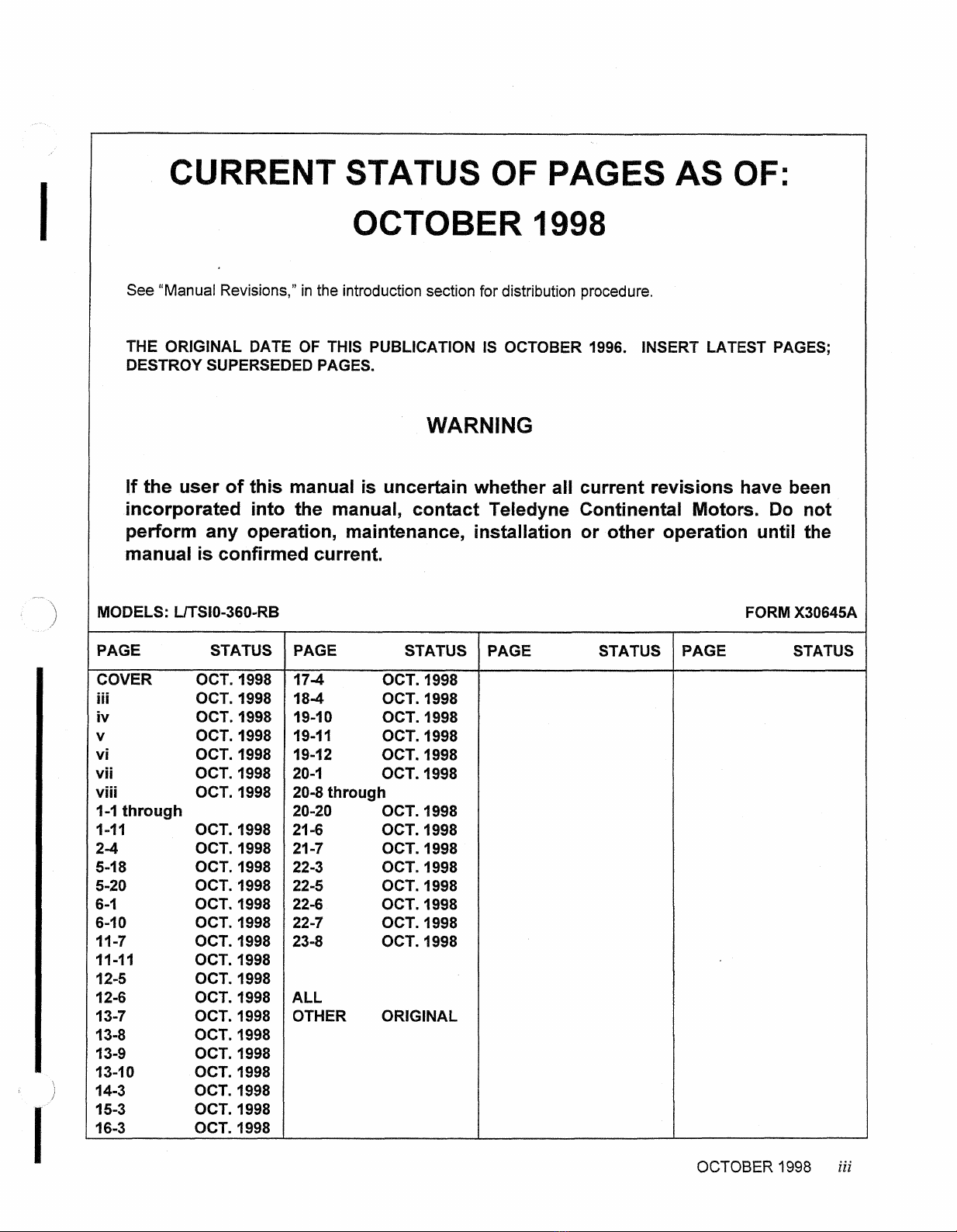
CURRENT
STATUS
OF
PAGES
AS
OF:
OCTOBER
1998
See "Manual Revisions,"in the introductionsection for distribution procedure.
THE ORIGINAL DATE
OF
THIS PUBLICATION IS OCTOBER
1996.
INSERT LATEST PAGES;
DESTROYSUPERSEDEDPAGES.
WARNING
If the user of this manual
is
uncertain whether all current revisions have been
incorporated into the manual, contact Teledyne Continental Motors. Do not
perform any operation, maintenance, installation
or
other operation until the
manual
is
confirmedcurrent.
OCTOBER
1998
iii
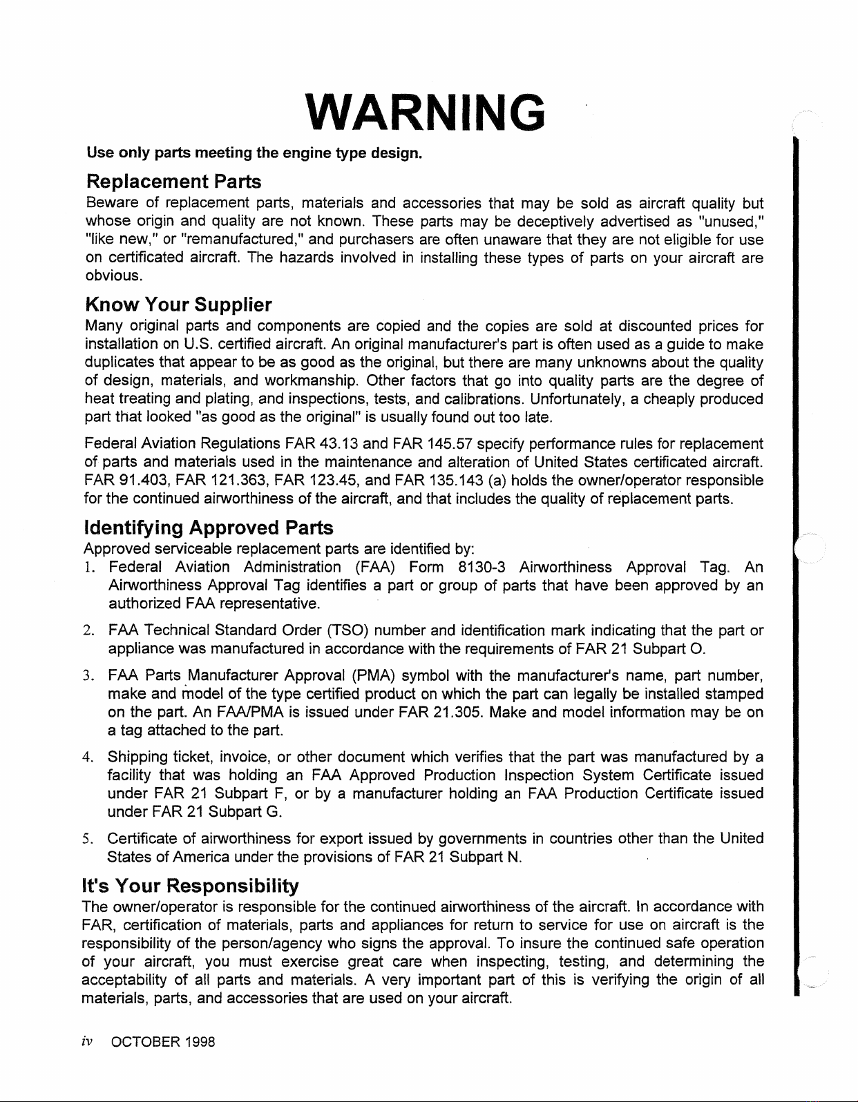
WARN
Use
only
parts
meetingthe engine
type
design.
Replacement Parts
Beware of replacement parts, materials and accessories that may be sold as aircraft quality but
whose origin and quality are not known. These parts may be deceptively advertised as "unused,"
"like new," or "remanufactured," and purchasersare often unaware that they are not eligible for use
on certificated aircraft. The hazards involved in installing these types of parts on your aircraft are
obvious.
Know
Your
Supplier
Many original parts and components are copied and the copies are sold at discounted prices for
installationon U.S. certified aircraft. An original manufacturer'spart is often usedas aguideto make
duplicatesthat appear to be as good as the original, butthere are many unknowns about the quality
of design, materials, and workmanship. Other factors that go into quality parts are the degree of
heat treating and plating,and inspections,tests, and calibrations. Unfortunately, a cheaply produced
part that looked"as goodas the original" is usuallyfound out too late.
FederalAviation Regulations FAR 43.13 and FAR
145.57
specify performance rules for replacement
of parts and materials used in the maintenance and alteration of United States certificated aircraft.
FAR
91.403,
FAR
121.363, FAR 123.45, and FAR 135.143
(a)
holdsthe ownertoperator responsible
for the continuedairworthinessof the aircraft, and that includes the quality of replacement parts.
Identiwing
Approved
Parts
Approved serviceable replacementparts are identified
by:
1.
Federal Aviation Administration (FAA) Form 8130-3 Airworthiness Approval Tag. An
Airworthiness Approval Tag identifies a part or group of parts that have been approved by an
authorized
FAA
representative.
2.
FAA Technical Standard Order (TSO) number and identification mark indicatingthat the part or
appliance was manufactured in accordancewiththe requirementsof FAR
21
Subpart
0.
3.
FAA Parts Manufacturer Approval (PMA) symbol with the manufacturer's name, part number,
make and model of the type certified product on which the part can legally be installed stamped
on the part. An FAA/PMA is issued under FAR 21.305. Make and model information may be on
a tag attachedto the part.
4.
Shippingticket, invoice, or other document which verifies that the part was manufactured by a
facility that was holding an FAA Approved Production Inspection System Certificate issued
under FAR 21 Subpart F, or by a manufacturer holding an FAA Production Certificate issued
under FAR 21 Subpart
G.
5.
Certificate of aiworthiness for export issued
by
governments in countries other than the United
States ofAmerica under the provisions of FAR 21 Subpart
N.
It's
Your
Responsibility
The ownertoperatoris responsiblefor the continuedai~lorthinessof the aircraft. Inaccordancewith
FAR, certification of materials, parts and appliances for return to service for use on aircraft is the
responsibilityof the personlagency who signs the approval. To insure the continued safe operation
of your aircraft, you must exercise great care when inspecting, testing, and determining the
acceptability of
all
parts and materials.
A
very important part of this is verifying the origin
of
all
materials,parts,and accessoriesthat are used on your aircraft.
iv
OCTOBER
4998
I
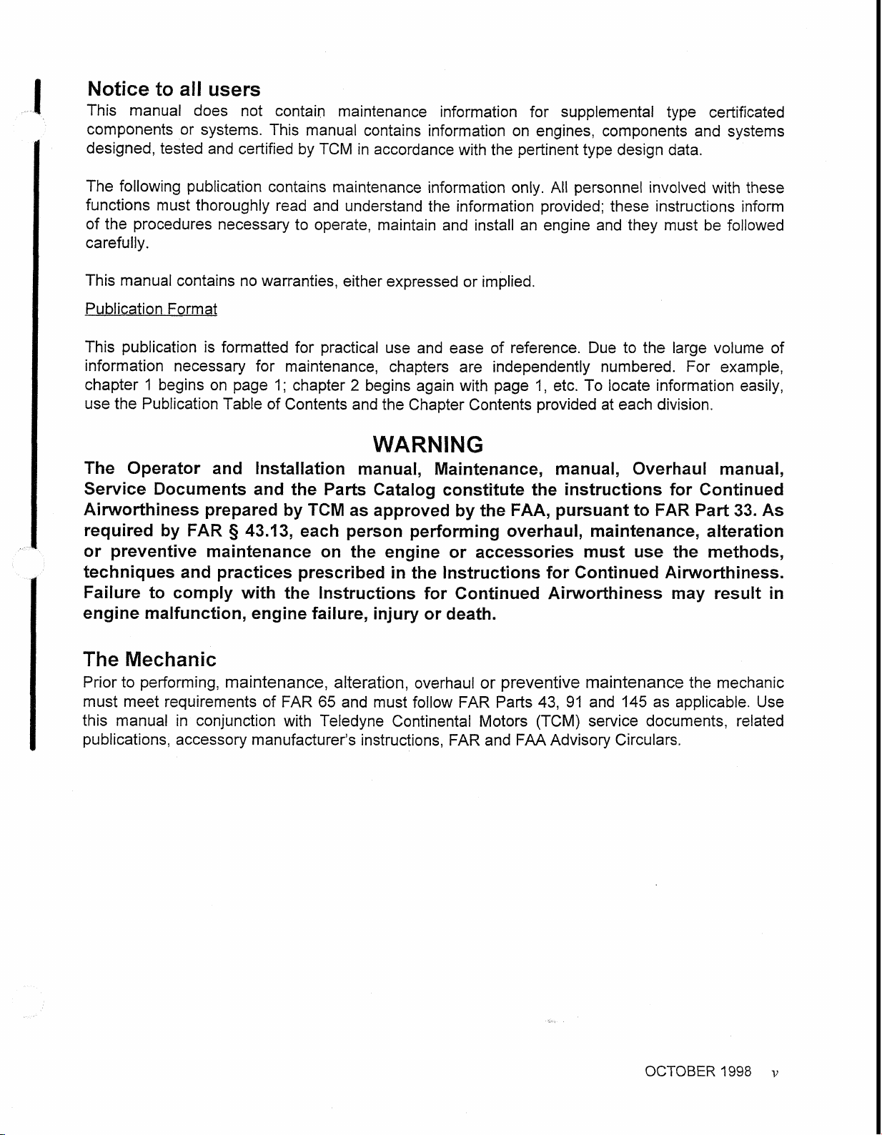
Notice
to
all
users
This manual does not contain maintenance information for supplemental type certificated
components or systems. This manual contains information on engines, components and systems
I
designed,tested and certifiedby TCM in accordance with the pertinenttype design data.
The following publication contains maintenance information only.
All
personnel involved with these
functions must thoroughly read and understandthe information provided; these instructions inform
of the procedures necessary to operate, maintain and install an engine and they must be followed
carefully.
This manual contains no warranties, either expressed or implied.
PublicationFormat
This publication is formatted for practical use and ease of reference. Due to the large volume of
information necessary for maintenance, chapters are independently numbered. For example,
chapter
1
begins on page
1;
chapter
2
begins again with page
1,
etc. To locate information easily,
usethe PublicationTable of Contents and the Chapter Contents provided at each division.
WARNING
The Operator and Installation manual, Maintenance, manual, Overhaul manual,
Service Documents and the Parts Catalog constitute the instructions for Continued
Airworthiness prepared byTCM as approved bythe
FAA,
pursuantto FAR Part33. As
required by
FAR
§
43.13, each person performing overhaul, maintenance, alteration
or preventive maintenance on the engine or accessories must use the methods,
techniques and practices prescribed inthe lnstructions for Continued Airworthiness.
Failure to comply with the lnstructions for Continued Ai~lorthinessmay result in
engine malfunction, engine failure, injury or death.
The Mechanic
Prior to performing, maintenance, alteration, overhaul or preventive maintenance the mechanic
must meet requirements of FAR
65
and must follow
FAR
Parts
43,
91
and
145
as applicable. Use
this manual in conjunction with Teledyne Continental Motors (TCM) service documents, related
publications,accessory manufacturer'sinstructions,FAR and FAAAdvisory Circulars.
OCTOBER
1998
v
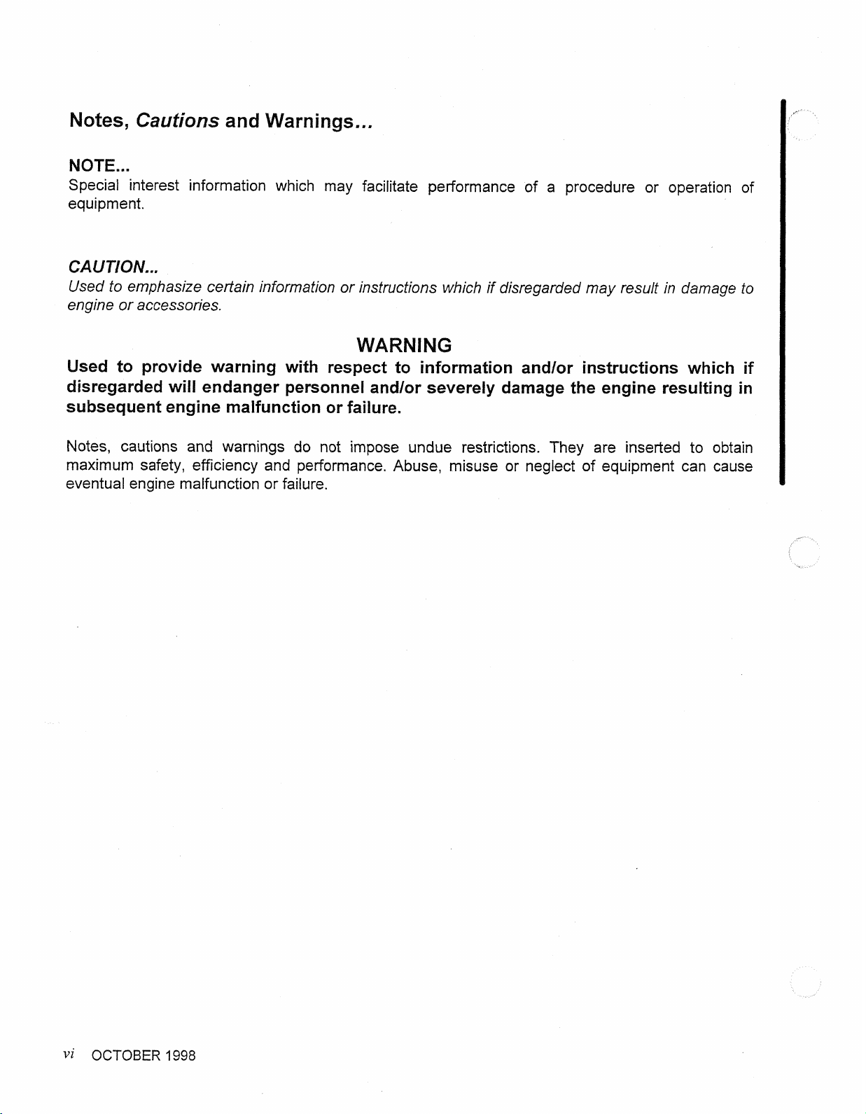
Notes,
Cautions
and Warnings
...
NOTE...
Special interest information
which
may facilitate performance
of
a procedure or operation of
equipment.
CAUTION
...
Used to emphasize certain information or instructions which if disregardedmay result in damage
to
engine or accessories.
WARNING
Used
to
provide warning with respect to information andlor instructions which
if
disregarded
will
endanger personnel andlor severely damage the engine resulting in
subsequent engine malfunctionor
failure.
Notes, cautions and warnings do not impose undue restrictions.
They
are inserted to obtain
maximum safety, efficiency and pelformance. Abuse, misuse or neglect of equipment can cause
eventual engine malfunction or failure.
vi
OCTOBER
1998
Publication Table Of Content
COVER
PAGES
PAGE
...
Status Page
...................................................................................................................
111
......................................................................................................................
WARNING
iv
.........................................................................................................
Notice
To
All Users
v
Notes, Cautions andWarnings
.......................................................................................
vi
Chapter Index
..........................................................................................................................
CHAPTER PAGE
............................................................................................................
1 Introduction 1-3
...............................................................................................
2 Tools (Maintenance) 2-1
3 Approved Products
............................................................................................
3-1
4 Airworthiness Limitations
........................................................................................
4-1
5
Time LimitslOperationalInspection/Troubleshooting
.............................................
5-1
6
UnpackingiDe-inhibitingllnstallation
&
Test
...........................................................
6-1
....................................................................................................
7
Servicing. Fluids 7-1
8
Engine Preservationand Storage
..........................................................................
8-1
................................................................................................
9 Standard Practices 9-1
Engine Maintenance
...........................................................................................
10-1
ExhaustSystem
....................................................................................................
11-1
IgnitionSystem
.....................................................................................................
12-1
Fuel Injection System
..........................................................................................
13-1
InductionSystem
.............................................................................................
14-1
Air ConditioningSystem
........................................................................................
15-1
16 ElectricalChargingSystem
...............................................................................
16-1
17 Starter
&
StarterAdapter
........................................................................................
17-1
18 Accessory Case
..................................................................................................
18-1
19 LubricationSystem
............................................................................................
19-1
20 CylinderAssembly
..............................................................................................
20-1
21 Crankcase
........................................................................................................
21-1
..................................................................................................
22 EngineDriveTrain 22-1
................................................................
23 Post MaintenanceAdjustmentAnd Test
23-1
OCTOBER
1998
vii
t
NTENTIONALLY
LEFT
BLANK
viii
OCTOBER
1998

CHAPTER 1
1-1. Introduction ....................................................................................................................1-3
1-2. Scope.............................................................................................................................1-3
1-3. Definition of Terms.........................................................................................................1-3
1-4. Manual Revisions...........................................................................................................1-3
1-5. Revision/Change Distribution.........................................................................................1-4
1-6. Related Publications.......................................................................................................1-4
1-7. Service Documents........................................................................................................1-5
1-8. Service Reports and Inquiries ........................................................................................1-5
1-9. Suggestions and Corrections .........................................................................................1-6
1-10. TCM Contact Information...............................................................................................1-6
1-11. Engine Model Description ..............................................................................................1-7
1-12. Engine Design Features.................................................................................................1-7
1-13. General ........................................................................................................................1-10
1-14. Engine Specifications...................................................................................................1-10
1-15. Operating Limits...........................................................................................................1-11
LIST OF ILLUSTRATIONS
Figure 1-1. L/TSIO-360-RB Top and Front View ..........................................................................1-8
Figure 1-2. L/TSIO-360-RB Side and Aft View .............................................................................1-9
1-1
Change 2

1-2
Change 2
INTENTIONALLY
LEFT
BLANK

1-1. INTRODUCTION
This maintenance manual and the publications listed in Section 1-6 contain the information
necessary to install, operate and maintain TSIO-360-RB or LTSIO-360-RB engines.
For a list of chapters contained in the manual, refer to the Chapter index on page vii. Each
chapter begins with a table of contents on the first page. Pages in the manual are numbered
consecutively by chapter; each chapter starts with page 1.
1-2. SCOPE
WARNING
Instructions in TCM manuals are applicable only to engines and parts
supplied by TCM. TCM Instructions for Continued Airworthiness should
not be used for non-TCM parts.
This publication contains information necessary to perform scheduled maintenance, adjust
and test L/TSIO-360-RB engines in their original, type certified configuration.
Installation of non-TCM parts on a TCM engine constitutes a deviation from TCM type-
design criteria. TCM has not participated in design, test, or certification of any non-TCM
parts. TCM does not provide product manufacturing specifications to aftermarket parts
manufacturers and accepts no liability for the suitability, durability, longevity, or safety of
such parts installed on TCM engines. Installation of non-TCM parts on a TCM engine must
be performed using Instructions for Continued Airworthiness prepared by the manufacturer
and approved by the FAA for the subject installation.
1-3. DEFINITION OF TERMS
In this manual, the terms front, rear, left and right refer to the engine as viewed by a pilot
sitting in the crew compartment. The accessory end is at the rear and the propeller is at the
front of the engine. Cylinders are numbered from the rear, with odd numbers on the right
and even numbers on the left.
1-4. MANUAL REVISIONS
The instructions in this manual represent the best and most complete information available
at the time of publication. Product or process improvements may trigger changes to existing
product design specifications or procedures contained in publications. As new technical
information becomes available, TCM will deliver the updated information to the customer in
the most expedient manner.
WARNING
New information may be contained in Teledyne Continental Motors
service documents. Service documents applicable to engines and
accessories within the scope of this manual must be complied with as
defined in these documents. This manual, and the manuals identified in
Section 1-6 constitute the Instructions for Continued Airworthiness
(ICAs) prepared by Teledyne Continental Motors and approved by the
Federal Aviation Administration (FAA).
1-3
Change 2
Teledyne Continental Motors releases publication changes in the form of either change
pages or complete publication revisions, depending upon the extent of change. Service
documents may supplement or replace technical information contained in one publication or
an entire series of publications. Such service documents represent a change to the
published ICA until the individual publications incorporate the latest technical information.

1-5. REVISION/CHANGE DISTRIBUTION
Document updates are available via TCMLINK upon notification of FAA document approval.
TCM notifies engine owners of technical publication changes free of charge. TCM notifies
current TCMLINK service subscribers as publications are updated. Current TCMLINK
service subscribers receive a complete publication library on CD delivered quarterly. Current
printed publication subscribers receive printed changes and revisions as they are released.
1-6. RELATED PUBLICATIONS
The following manuals contain additional information regarding operation, maintenance and
overhaul of L/TSIO-360-RB engines:
1. L/TSIO-360-RB Overhaul Manual, Form X 30596A Supplement 1.
2. Operation and Installation Manual, X30644.
3. Starter Service Instructions, Form X30592.
4. TCM Ignition Systems Master Service Manual, Form X40000.
5. TCM Aircraft Engine Service Documents.
For TCM product pricing information, request a TCM Publication Pricing Index from your
local TCM distributor or TCMLINK.com Powerstore.
6. Slick Ignition Systems Master Service Manual Index and Order Form No. F-1100. Order
through:
Slick Aircraft Products, Unison Industries
530 Blackhawk Park Avenue
Rockford, IL 61104
ATTN: Subscription Department
USA
Phone: (815) 965-4700
www.unisonindustries.com
7. Precision Fuel System Manual, Form 15-895, Index of Manuals, Bulletins and Service
Information Letters. Order through:
Precision Airmotive LLC
14800 40th Avenue NE
Marysville, WA 98271
USA
Phone: (360) 651-8282
www.precisionairmotive.com
8. American Society for Testing and Materials (ASTM). Order through:
ASTM International
PO Box C700
West Conshohocken, PA 19428-2959
USA
Phone: (610) 832-9555
www.astm.org
1-4
Change 2

1-7. SERVICE DOCUMENTS
Six categories of Service Documents may be issued by TCM ranging from mandatory
(Category 1) to informational (Category 6). Definitions of the categories are listed below:
NOTE: Upon FAA approval, TCM service documents are published and available on
TCMLINK. Service Documents which contain updates to the Instructions for
Continued Airworthiness must be inserted in the affected manual until such time the
manual is revised to include the Service Document instructions or the Service
Document is cancelled or superseded. The Service Document cover page shall list
specific engine manuals affected by the Service Document’s changes to the
Instructions for Continued Airworthiness.
Category 1: Mandatory Service Bulletin (MSB)
Used to identify and correct a known or suspected safety hazard which has been incorporated in
whole or in part into an Airworthiness Directive (AD) issued by the FAA or have been issued at
the direction of the FAA by the manufacturer requiring compliance with an already-issued AD (or
an equivalent issued by another country’s airworthiness authority). May contain updates to
TCM’s Instructions for Continued Airworthiness to address a safety issue.
Category 2: Critical Service Bulletin (CSB)
This category identifies a condition that threatens continued safe operation of an aircraft,
persons or property on the ground unless some specific action (inspection, repair, replacement,
etc.) is taken by the owner or operator. Documents in this category are candidates for
incorporation into an FAA Airworthiness Directive. May contain updates to TCM’s Instructions for
Continued Airworthiness to address a safety issue.
Category 3: Service Bulletin (SB)
Information which the product manufacturer believes may improve the inherent safety of an
aircraft or aircraft component; this category includes the most recent updates to Instructions
for Continued Airworthiness.
Category 4: Service Information Directive (SID)
The manufacturer directs the owner/operator/mechanic in the use of a product to enhance
safety, maintenance or economy. May contain updates to TCM’s Instructions for Continued
Airworthiness in the form of maintenance procedures or specifications.
Category 5: Service Information Letter (SIL)
This category includes all information (not included in categories 1 through 4) that may be useful
to the owner/operator/technician. May contain updates to TCM’s Instructions for Continued
Airworthiness for optional component installations, which are not covered in the Applicable
Operator, Maintenance, or Overhaul Manuals.
Category 6: Special Service Instruction (SSI)
This category is used to address an issue limited to specific model and/or serial number
engines. TCM will distribute SSI notification directly to the affected engine’s owners. SSIs will not
be included in the general service document set but will be made available through TCM
Customer Service to owners of the affected engines only. An SSI may contain updates to the
Instructions for Continued Airworthiness applicable to the listed engines.
1-5
Change 2
1-8. SERVICE REPORTS AND INQUIRIES
If for any reason you have an inquiry or require technical assistance, contact your local TCM
distributor or TCM field representative. TCM service bulletins are available through your
distributor or from TCMLINK.

1-9. SUGGESTIONS AND CORRECTIONS
Teledyne Continental Motors solicits and encourages user comments regarding suggested
changes to this manual. Direct recommended changes or questions to the attention of
“Publications” at the TCM address listed under “TCM Contact Information.”
Notify TCM Customer Service immediately, using our toll-free number, if you discover
incorrect information which adversely affects safety.
1-10. TCM CONTACT INFORMATION
Teledyne Continental Motors is available to answer technical questions and encourages
suggestions regarding products, parts, or service. If customers have an inquiry or require
technical assistance, they should contact their local TCM distributor or TCM field
representative. To contact TCM, refer to the contact information below:
1-6
Change 2
Teledyne Continental Motors, Inc.
P. O. Box 90
Mobile, AL 36601
Customer Service Phone Number: 888-826-5465 toll free within the U.S.
International: 1-251-438-3411
Internet Address: http://www.tcmlink.com
1-11. ENGINE MODEL DESCRIPTION
Horizontally Opposed Cylinders
Left Hand Rotation
TS I O- 360 -RB1
Specification Number
Model Identifier
Cubic Inch Displacement
Turbo-Supercharged
Fuel Injected
B
Shipping Designation
L
Horizontally Opposed Cylinders
Left Hand Rotation
TS I O- 360 -RB1
Specification Number
Model Identifier
Cubic Inch Displacement
Turbo-Supercharged
Fuel Injected
B
Shipping Designation
L
1-12. ENGINE DESIGN FEATURES
L/TSIO-360-RB series engines are air-cooled, with six horizontally opposed, incline valve,
cylinders. Cylinder displacement of 360 cubic inches is achieved with a 4.4 inch bore and
3.875 inch stroke. L/TSIO-360-RB engines are fuel injected and turbocharged. The
crankshaft is equipped with pendulum type counterweight dampers to suppress torsional
vibrations.
L/TSIO-360-RB series engines have a dowelled, six bolt hole configuration propeller flange.
A mounting pad is provided to utilize a hydraulic controlled governor for a constant speed
propeller. The engine is designed with a wet-sump and a positive displacement oil pump.
When properly adjusted, under normal conditions, desired oil pressure is maintained by a
pressure relief valve. Engine cranking is accomplished by a geared, right angle driven
starter adapter and a direct current starter motor.
The L/TSIO360-RB incorporates provisions for a belt-driven alternator mounted on the front
of the 1-3-5 side of the crankcase. The engine is equipped with two independent, gear
driven magnetos mounted on the accessory case. The exhaust and turbocharger systems
are supplied with the engine.
NOTE: Figures depicted in this publication are for illustration purposes only,
Illustrations represent the most common system configurations available for the
engine model and are not drawn to scale. They are not intended to be accurately
detailed illustrations of any specific engine model, part, or equipment. Detailed
illustrations of each engine model specification may be found in the TCMLINK online
parts catalogs.
1-7
Change 2
1-8
Change 2
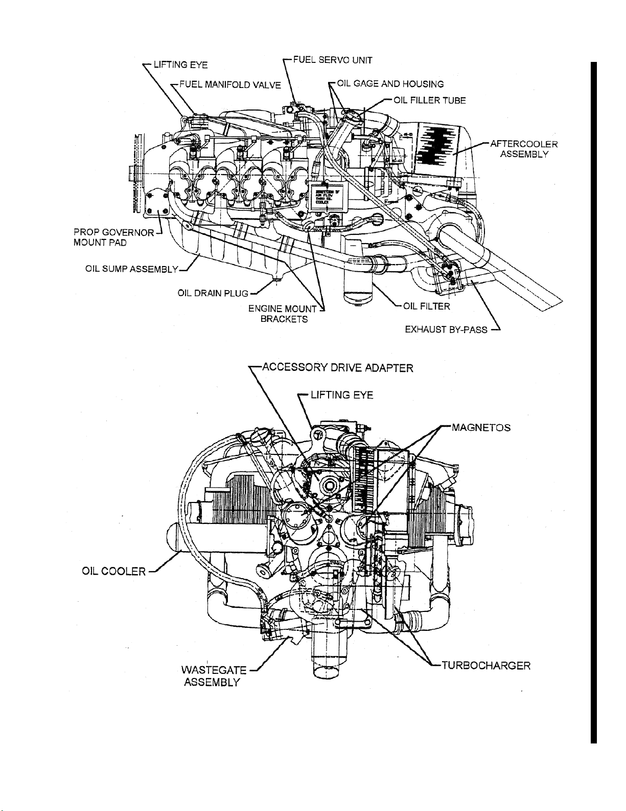
Figure 1-1. L/TSIO-360-RB Top and Front View
1-9
Change 2
Figure 1-2. L/TSIO-360-RB Side and Aft View

1-13. GENERAL
Operating limits and specifications listed in this section apply to the L/TSIO-360-RB aircraft
engine model. Consult the L/TSIO-360-RB Operation and Installation Manual, Form X30644
for additional operating specifications.
For L/TSIO-360-RB time between overhaul (TBO), see Section XX or the latest TCM Time
between Overhaul Service Bulletin. TCM aircraft accessories are subject to the same
overhaul requirements as the engine, with criteria for service and longevity outlined in
applicable service manuals and service documents, unless otherwise specified.
1-14. ENGINE SPECIFICATIONS
Model: L/TSIO-360-RB
Brake Horsepower
Rated maximum Continuous Operation..........................................................................220
Cylinders
Arrangement.........................................................horizontally opposed individual cylinders
Compression ratio .........................................................................................................7.5:1
Firing Order
TSIO-360-RB...................................................................................................... 1-6-3-2-5-4
L/TSIO-360-RB................................................................................................... 1-4-5-2-3-6
Number of cylinders.............................................................................................................6
Bore (inches) ................................................................................................................4.438
Stroke (inches) .............................................................................................................3.875
Piston Displacement (cubic inches) ................................................................................360
Fuel
Fuel Control System...................................................................................Precision RSA-5
Minimum Fuel Grade............................................................................ Refer to Section 7-3
Ignition Timing
Right magneto, degrees BTC.....................................................................................22°±1°
Left magneto, degrees BTC .......................................................................................22°±1°
Spark Plug........................................................................................................TCM 630049
1-10
Change 2
Champion RHM38E
Spark plug gap ................................................................Use manufacturer’s specified gap
Oil
TCM Approved Oils.............................................................................. Refer to Section 7-2
Below 40° Ambient (Sea Level)...........................TCM Approved SAE 30 or Multi Viscosity
Above 40° Ambient (Sea Level)..........................TCM Approved SAE 50 or Multi Viscosity
Sump Capacity (US Quarts..............................................................................................8.0
Oil Consumption Formula......................................................................... 0.006 X %Powe
r
NOTE: One quart = 1.875 pounds 100
Engine Direction of Rotation
TSIO-360-RB........................................................................................................ Clockwise
LTSIO-360-RB..........................................................................................Counterclockwise

TSIO-360 Accessory Drive Ratios
Drive rations for LTSIO-360-RB engines are the same as TSIO-360 except the direction of
rotation is reversed.
CAUTION…A removable oil transfer plug conducts oil pressure from the propeller governor
through the crankshaft to the propeller hub. When a test club or fixed propeller is used for
testing purposes, the propeller governor cover must have an internal grooved surface to
allow the circulating oil to lubricate the front main bearings. The governor pad is not used if a
propeller governor is installed.
Accessory Direction of Rotation Drive Ratio
Magneto Clockwise 1.5:1
Starter Clockwise 24.73:1
Propeller Governor1Clockwise 1:1
Fuel injection Pump Counterclockwise 1:1
Freon Compressor2Clockwise 1.545:1
Accessory Drive Pad3Counterclockwise 1.545:1
1 Drive is a modified AND 20010; supplied with a cover plate
2 Ration is for six inch diameter driven sheave
3 Drive is a modified AND 20000; supplied with a cover plate
1-15. OPERATING LIMITS
Rated Maximum Continuous Operation...............................................220 HP@2600 RPM
Recommended Minimum for Idle.....................................................................700 ±25 RPM
Manifold Pressure (in. Hg).................................................................................... 38.0 PSIA
Oil Pressure
Minimum (Idle)............................................................................................................10 PSI
Maximum (Cold Oil)..................................................................................................100 PSI
Normal Operation..................................................................................................30-60 PSI
Oil Temperature
Minimum for Takeoff...................................................................................................100° F
Maximum Limit............................................................................................................240° F
Turbocharger Inlet Temperature
Maximum Continuous...............................................................................................1650° F
Maximum, 60 seconds..............................................................................................1700° F
Cylinder Head Temperature*
Recommended Maximum Operating Temperature....................................................420° F
Limit............................................................................................................................480° F
1-11
Change 2

1-12
Change 2
INTENTIONALLY
LEFT
BLANK
Table of contents
Other Teledyne Continental Motors Engine manuals


Popular Engine manuals by other brands

Power Tec
Power Tec 25A owner's manual

Vanguard
Vanguard 610000 Operator's manual

Oriental motor
Oriental motor FPW Series operating manual

Oriental motor
Oriental motor BLF Series operating manual

woodmizer
woodmizer D42 Safety, Operation, Maintenance & Parts Manual

UDI R/C
UDI R/C UD1609 operating instructions


