Teledyne Lecroy PCI Express Gen4 M.2 User manual

Introduction
The Teledyne LeCroy PCI Express Gen4 M.2 MKey Interposer CrossSync Phy, which is used with Summit T54 Protocol
Analyzers, enables PCIe®bus traffic between a system board or tablet and a M.2 connector on a PCIe M.2 device to be
monitored, captured, and recorded for protocol analysis. The M.2 interposer will support analysis for PCIe host interfaces
such as SATAExpress (AHCI/PCIe) and NVM Express (NVMe) at data rates from 2.5 GT/s up to 16.0 GT/s and link widths
of up to x2 or up to x4.
The interposer supports side band signals such as PERST#, WAKE#, CLKREQ# and SMBus (SMBCLK, SMBDAT).The
M.2 technology specification includes two connector definitions: Socket 2 and Socket 3. Socket 2 keyed as “B” allows for
PCIe x2 interface for SSDs, WWAN or other non-storage devices. Socket 3 keyed as “M” is strictly for high-performance
storage, offering x4 lanes of bandwidth in this form factor. In some cases a “B/M” keyed SSD will also be available and it is
both a Socket 2 and 3 type. A “B”, “M” or a “B/M” keyed memory SSD can then be connected to a host based B or M
connector which is capable of supporting any of the devices mentioned above.
Teledyne LeCroy provides an interposer to use with M and B-M type memory modules. The interposer supports the 30mm,
42mm, 60mm, 80mm, and 110mm SSD lengths as well as 22mm and 30mm widths.
PCI Express Gen4 M.2 M-Key Interposer
PCI Express®Gen4 M.2 M-Key Interposer
CrossSync PHY
User Manual and Quick Start Guide
Before Starting
Use this document for quick installation and setup. If you experience problems or
need more information, see the product manuals available at the Teledyne LeCroy
web site or in the Documents folder in the PCIe Protocol Suite installation.
1

• PCI Express Gen4 M.2 M-Key Interposer Carrier
board
• Connector cable assembly 18 inches for
connection to host slot
• DC Power Adapter (+12V @ 3 Amps)
• Extension bracket kit (metal brackets with clip)
supporting M.2 devices of 60, 80 and 110mm
devices (depending on purchased configuration
two more bracket sizes 30 and 42mm included)
• Thumbscrew, standoff and locknut
• User Manual and Quick Start Guide (this
document)
2
Interposer Cable Assembly Installatio
If required, install a different extension bracket to the small PCB at the end of the 18" interposer cable. The extension
brackets are provided to allow the user to attach and secure the Teledyne LeCroy M.2 interposer cable on the host system
which usually supports different M.2 card form factors. Follow below instructions to install the extension brackets that will fit
your application. Depending on configuration purchased there are two 18” interposer cable versions, follow the instructions
for the cable at hand.
Cable Assembly for Snap-on Attachment with 30mm PCB Configuration
This option uses a snap-on bracket. The Teledyne LeCroy M.2 Interposer Extension Bracket Kit contains the items listed
here (See figure below).
•Type - 22110 Extension Bracket
•Type - 2280 Extension Bracket
•Type - 2260 Extension Bracket
•Type - 2242 Extension Bracket
M2 Interposer Extension Bracket Kit
3
Components
The Teledyne LeCroy Gen4 M.2 MKey Interposer CrossSyncPhy kit has the following components:

1. Place the Extension bracket aligned with the alignment holes in the PCB (marked G4 M.2 M-Key Cable 2230). The bot-
tom of the PCB is shown below.
2. Select the appropriate bracket for your application (Type-2242 as example here).
3. Make sure the text "Type - 2242" on the bracket is facing the top of the PCB where the cables are attached.
4. The extension bracket with clip is to be inserted into the Interposer CableAssembly PC Board.
(AType - 2242 Extension Bracket is shown being inserted into an M-Key Type CableAssembly PC Board below just as
an example. The cable soldered to the top of the PCB was removed in the drawing below for clarity.)
5. Insert the Extension bracket with the clip into the PCB with cables attached. Ensure that the alignment pins on the
bracket slip into the holes on the PCB. It may be easier to install the bracket one alignment pin at a time. First, push the
lower alignment pin into the lower PCB hole and then slide-in the bracket and push the second alignment pin into the
second PCB hole. See the images below.
6. The view from the top side of the PCB is shown below with a Type-2280 Extension Bracket.
Warning! Attempting to use the board without the extension bracket and properly secured to the host will cause damage
to the plug-in card of the interposer cable and warranty will be voided.

Cable Assembly for Screw Attachment with 42mm PCB Configuration
The cable comes already with the Type 2260 bracket extension installed. To install a different bracket follow below
procedure. The Teledyne LeCroy M.2 Interposer Extension Bracket Kit contains the items listed below. The items are
shown in the figure below.
•Type 22110 Extension bracket
•Type 2280 Extension bracket
•Type 2260 Extension bracket.
•Screws to attach the Extension bracket to the interposer CableAssembly
M2 Interposer Extension Bracket Kit

For this cable configuration screws are used to hold the bracket to the PC Board. The assembly process for swapping the
default Type 2260 bracket with the Type 2280 is described below (follow the same steps for the Type 22110 bracket).
1. First remove the two Phillips head screws, then remove the Type 2260 Extension bracket.
2. Place the Type 2280 Extension bracket aligned with the counter sink screw holes.
3. Make sure the text "Type 2280" on the bracket is facing the top of the PCB where the cables are attached.
4. Insert the screws and tighten them using a 1.4mm Phillips or flat blade screw driver.
5. The view from the top side of the PCB is shown below. The text "Type 2280" is clearly visible.
Attaching the Cables to the Interposer
1. Once the cable assembly has been completed (Method One or Method Two) the next step is to attach the cables to the
Interposer as shown below.
2. Connect the cable ends to the interposer pod. There is a power cable, a sideband signals cable and a high speed sig-
nals cable. These three cables have different connectors and are keyed. Be careful to install the connectors in the right
orientation (following labels) and do not force them. See diagram below.
Phillips head
screws
Warning! Attempting to use the board without the extension bracket and properly secured to the host will cause
damage to the plug-in card of the interposer cable and warranty will be voided.

Interposer DUT Standoff Installation
A flexible attachment M.2 standoff assembly is provided for the different types of DUTs supported which are 2230, 2242,
3042, 2260, 2280, and 22110. Move the M.2 standoff based on the DUT Type. The standoff will be attached to 2280
location by default. The DUT is secured by a thumbscrew on the top side and a standoff with a locknut on the bottom side
which can be removed by hand or with a nut driver. This is to secure the DUT and not DUT bracket. (see drawings below).
Exploded View
Installed
Installed Side Profile
4

Hardware Installation
To use this interposer:
1. Set the SW1 DIP switches to the desired clock selection.
Note: "HOST_CLK" should be the default setting unless you are using an external clock reference source.
2. Move the stand off from the default position to the position required by the DUT.
3. Install the M.2 SSD device under test (DUT) into the connector on the interposer as shown (will fit 30 mm, 42mm,
60mm, 80mm and 110mm).
4. Connect the Summit Analyzer to the interposer using the high speed serial cables (If using Summit T54 use Gen4 Y
cable PE021UCA-X. If using Summit T54 with Gen4 Phy use Gen4 straight cable PE020UCA-X).
5. Connect the analyzer to a host machine using the USB port on the front panel of the Summit analyzer.
6. If not already done, install the PCIe ProtocolAnalysis on the host machine.
7. Connect 12V DC using the AC adapter supplied with the interposer. (Make sure that the AC adapter is powered on).
8. Power On the Analyzer and wait for it to be recognized by the application. Note: If prompted to update the firmware
please do that before proceeding.
9. Start recording with the analyzer.
10. Power on the host machine.
11. Launch the Teledyne LeCroy software application to monitor, record and view PCI Express traffic passing through the
M.2 Interposer.
12. Power on the system under test.
Note: Step 8, 9, and 10 are needed in this order for "Power ON" traces.
Note: Use the link width control button SW2 to match the minimum physical lane width of the host and device.
Summit T54
Analyzer
PCI Express Gen4 M.2 MKey Interposer CrossSync Phy Interposer Interconnection Overview
Gen4 x4 Straight
Cable PE020UCA-X
12V DC from Adapter
475mm (18.7")
(not to scale)
Note: M/B-M Type Interposer is shown below.
Host Slot Connector
Power Cable
HighSpeed
Cable
Sideband
Cable
Clock Source Configuration: SW2
External Clock Inputs
DUT Power LED Status: SW4
Active Width Control: SW3
Device Under Test (DUT)
Carrier board
compatible with:
22x30, 22x42,
22x60, 22x80 &
22x110
Side Band Test Points
Interposer Configurations
Part No Connector
Key Slot Key Designed For
B M B-M
PE186UIA-X M-Key M-Key No Yes Yes
5

Clock Configuration and Other Switch Settings
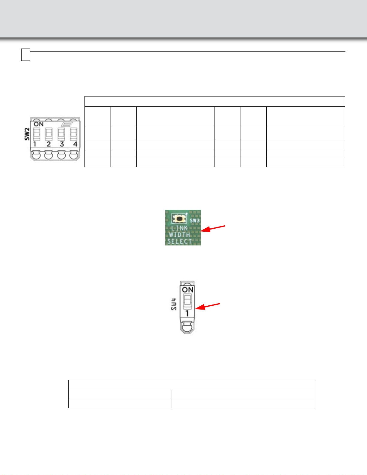
SW2: The source for the reference clock used by the analyzer to record PCI Express traffic is configurable according to
below table for SW2. Make sure clock source in Recording Options in the PCIe Protocol Analysis application is set to
External.
Note: Factory default is host clock: SW2.1 = ON, SW2.2 = ON, SW2.3 = ON, SW2.4 = ON
Note: Other switch configurations (other than those shown in the table above) are invalid.
Note: External input clocks can be HCSL, LVPECL, LVDS or any single ended standard input voltage amplitude not to
exceed 800mV.
SW3: A pushbutton SW3 is used to turn off the terminations and remove all loads on the unused interposer receivers
depending on the maximum number of lanes to be analyzed. Press the pushbutton switch (SW3) to move to the next active
width as indicated by the LEDs (next to the switch on the interposer.
DUT Power LED Status on Interposer
SW4: This switch connects the DUT power indication LEDs to the bus power. In some systems with Hot-Plug management
the Power Indication LEDs on the interposer may prevent the host system from turning ON bus power to the device, if this
happens disconnect the LEDs using SW4 to allow proper bus power operation.
SW2: Clock Source Control
SW2.1 SW2.2 Reference Clock Source
for Downstream Analysis SW2.3 SW2.4 Reference Clock Source
for Upstream Analysis
ON ON Host System PCIe Slot
Connector ON ON Host System PCIe Slot
Connector
OFF ON US_CLK from MMCX connector OFF ON US_CLK from MMCX connector
ON OFF DS_CLK from MMCX connector ON OFF DS_CLK from MMCX connector
OFF OFF No clocks supplied to analyzer OFF OFF No clocks supplied to analyzer
SW4: Link Width Select LED
ON LED Connected (Default)
OFF LED Disconnected
SW3 Active Link Width Select
6
SW4 DUT Power LED

Recording Traffic
After you have set up the hardware and software, you can record traffic.
For instructions on setting up and implementing a recording, please refer to the PCI Express Protocol Analysis Summit T4
Gen4 PCI Express Analyzer User Manual.
SW501: This switch selects the protocol analyzer clock on cable B (DS) or cable A (US) to be monitored on J607 and J608.
S501: Select Protocol Analyzer Clock to Monitor
ON Protocol Analyzer DS Clock (Cable B)
OFF Protocol Analyzer US Clock (Cable A)
Side Band Test Point Header J6207
Connector Pin Number Signal Name Connector Pin Number Signal Name
1 No Connection 17 VIO_CFG_HDR
2 No Connection 18 No Connection
3 CLK_32KHZ_SUSCLK_HDR 19 PERST#IN_HDR
4 No Connection 20 No Connection
5 GPIO_9_DAS_DSS_N_LED1_N_HDR 21 SMCLK_HDR
6 No Connection 22 No Connection
7 ALERT#IN_HDR 23 DEVSLP_DGND_HDR
8 No Connection 24 No Connection
9 PEDET_HDR 25 WAKE#_HTR
10 No Connection 26 No Connection
11 PWRDIS_HDR 27 CLKREQ#IN_HDR
12 No Connection 28 No Connection
13 PLN#_HDR 29 SMDAT_HDR
14 No Connection 30 No Connection
15 PLA_S3#_HDR 31 No Connection
16 No Connection
7

CrossSync PHY
Depending on the configuration, the Teledyne LeCroy PCI Express Gen4 x4 M.2 M-Key Interposer includes CrossSync
PHY capability, enabling:
•Easy signal access to sideband signals, power rail and refclk probing points
•Pre-installed connections on data lanes for Teledyne LeCroy DH Series high-bandwidth differential oscilloscope
probes (optional)
•Time-synchronization and integrated cross-analysis between PETracer protocol analysis software and MAUI
oscilloscope software (optional)
Signal Name PE210UIA-X PE210UIA-X-1PHY PE210UIA-X-2PHY PE210UIA-X-4PHY
Pin Headers
CLK_32KHZ SUSCLK X X X X
DAS/DSS LED_1# X X X X
ALERT#IN X X X X
PEDET X X X X
PWRDIS X X X X
PLN# X X X X
PLA_S3# X X X X
VIO_CFG X X X X
PERST#IN X X X X
SMB_CLK X X X X
DEVSLP X X X X
WAKE# X X X X
CLKREQ#IN X X X X
SMB_DATA X X X X
MMCX Connectors
Refclk X X X X
3.3V rail voltage X X X X
3.3V rail current X X X X
DH Series Differential Probe Connections (Optional)
L0 Upstream X X X
L0 Downstream X X X
L1 Upstream XX
L1 Downstream XX
L2 Upstream X
L2 Downstream X
L3 Upstream X
L3 Downstream X
8

PCI Express 3.0 - CrossSync PHY and Compliance Test Capable
Recommended Oscilloscope Probes
Oscilloscope Software Options
The Oscilloscope Software options allow you to enable CrossSync PHY functionality on installed CrossSync software.
Recommended Oscilloscopes
CrossSync PHY is compatible with all LabMaster 10 Zi and WaveMaster 8 Zi series oscilloscopes. Below are some
recommendations for example test configurations.
PCI Express 4.0 - CrossSync PHY and Compliance Test Capable
Product Description Product Code
13 GHz (or higher), 40 GS/s, 4ch, 64 Mpts/Ch Serial Data Analyzer
with 6.5 Gb/s Serial Trigger, 8b/10b and 64b/66b decode. SDA 813Zi-B
Product Description Product Code
High-speed Data Signals
8 GHz differential probe with ProLink interface DH08-PL
13 GHz differential probe with ProLink interface DH13-PL
16 GHz differential probe with ProLink interface DH16-PL
20 GHz differential probe with ProLink interface DH20-PL
25 GHz differential probe with 2.92 mm interface DH25-2.92MM
30 GHz differential probe with 2.92 mm interface DH30-2.92MM
Rail Voltage/current Points
Power/Voltage Rail Probe. 4 GHz bandwidth, 1.2x attenuation, ±30V offset, ±800mV RP4030
Product Description Product Code
CrossSync PHY option for LabMaster 10 Zi - sync oscilloscope with PCIe Protocol Analyzer hardware LM10Zi-CrossSyncPHY-PCIe
CrossSync PHY option for WaveMaster 8 Zi - sync oscilloscope with PCIe Protocol Analyzer hardware WM8Zi-CrossSyncPHY-PCIe
Product Description Product Code
25 GHz (or higher), 80 GS/s, 4 Ch, 32 Mpts/Ch LabMaster 10 Zi Acquisition Module LabMaster 10-25Zi-A
LabMaster Master Control Module LabMaster MCM-Zi-A

Enabling CrossSync PHY Capability
Use the following procedure to enable CrossSync PHY for your the interposer:
1. Locate any miscellaneous signals to be probed.
Top View
2. Locate the PCIe Express pairs probe points, as located on the left and right sides of the interposer.
Left Side View
Right Side View
Buffered Refclk
Copy (UMC)
Pin Header for
Sideband Signals
3.3V Rail Voltage
(UMC)
3.3V Rail Current
shunt (1V=1A)
(UMC)
Passive Probe
Grounds
Upstream Signal Probe
Points (Optional)
Downstream Signal
Probe Points(Optional)

3. Connect the oscilloscope probes to the PCI express signals as shown in the figure below.
Connect each Oscilloscope Probe to the
Required PCIe Bus Signal
Interposer Ready for a ScopeAnalysis of a
PCIe x2 bus

Teledyne LeCroy Customer Support
Online Download
Periodically check the Teledyne LeCroy Protocol Solutions
Group web site for software updates and other support
related to this product. Software updates are available to
users with a current Maintenance Agreement.
Web: teledynelecroy.com/tm/software/PCIe
E-mail: [email protected]
Support: teledynelecroy.com/support/contact
Trademarks and Servicemarks
TeledyneLeCroy, PCIe ProtocolAnalysis, PCIe Protocol Suite and Summit
T416, Summit T48 and Summit T54 are trademarks of Teledyne LeCroy.
All other trademarks are property of their respective companies.
Changes
Product specifications are subject to change without notice.
Teledyne LeCroy reserves the right to revise the information in this
document without notice or penalty.
Copyright
© 2021 Teledyne LeCroy, Inc. All rights reserved. Part Number: 932897-00 Rev A
This document may be printed and reproduced without additional permission, but all copies should contain this copyright
notice.
Environmental Conditions
• Temperature: Operating 41° F to 104° F (5° C to 40° C)
• Temperature: Non-Operating -4° F to 140° F (-20° C to 60° C)
• Humidity: Operating 5% to 80% RH (non-condensing) @ <= 86° F or <= 30° C
• Humidity: Operating 50% max RH (non-condensing) @ 104° F or 40° C
9
Table of contents
Other Teledyne Lecroy PCI Card manuals
Popular PCI Card manuals by other brands

ICP DAS USA
ICP DAS USA PCI-1202 Series user manual

StarTech.com
StarTech.com PCI312PUSB/LP quick start guide

Matrox
Matrox CompressHD Installation and user guide

DaytonAudio
DaytonAudio KABD Series user guide

Advantech
Advantech PCI-1730U user manual

CommTech
CommTech FASTCOM 422/4-PCI Hardware reference manual