Teledyne Oceanscience rapidCAST User manual

Information included herein is controlled by the Export Administration Regulations
(EAR) and may require an export license, license exception or other approval from the
appropriate U.S. Government agency before being exported from the United States or
provided to any foreign person. Diversion contrary to U.S. law is prohibited.
rapidCAST™
User’s Guide
P/N 95J-8000-00 (March 2018)
© 2018 Teledyne Oceanscience, Inc. All rights reserved.

Page ii
EAR-Controlled Technology Subject to Restrictions Contained on the Cover Page.
TABLE OF CONTENTS
INTRODUCTION .................................................................................................................................................1
RAPIDCAST OVERVIEW.......................................................................................................................................3
Terminology .................................................................................................................................................4
Mechanical Requirements ...........................................................................................................................6
Electrical Requirements ...............................................................................................................................8
Power Connectors................................................................................................................................8
Power Cable Connections ....................................................................................................................9
Performance Specifications and Operational Limits ....................................................................................11
INSTALLATION...................................................................................................................................................14
Unpacking the rapidCAST system.................................................................................................................15
Safety ...........................................................................................................................................................15
Important Safety Warnings ..................................................................................................................15
Important Deployment Warnings ........................................................................................................16
Lockout Procedure ...............................................................................................................................16
Installing the rapidCAST Interface Software ................................................................................................16
Software Architecture ..........................................................................................................................17
A Tour of the RapidCAST Interface.......................................................................................................17
Cable Connections........................................................................................................................................18
Antenna Position..........................................................................................................................................22
Switch Functions ..........................................................................................................................................23
LED Functions...............................................................................................................................................24
Installing the rapidCAST System...................................................................................................................25
Environmental Conditions....................................................................................................................25
Lifting the RapidCAST System...............................................................................................................26
Installing the Pipe Mount .....................................................................................................................27
Installing the Winch on the Pipe Mount ..............................................................................................28
Installing the Control Module ..............................................................................................................29
Line Properties .....................................................................................................................................30
Line Routing Procedure ........................................................................................................................31
Installing and Connecting the Probe ....................................................................................................32
Installing the Probe Software.......................................................................................................................33
Verifying Probe Communications.................................................................................................................33
INITIAL SETUP ...................................................................................................................................................35
Power up Sequence .....................................................................................................................................36
Connecting the Winch to a PC......................................................................................................................36
Verifying Basic Motion Functionality ...........................................................................................................37
Adjusting the LevelWind Position ................................................................................................................38
Line Management ................................................................................................................................39
Checking for Line Fouling .....................................................................................................................39
Defining Positions ........................................................................................................................................40
Setting the Home Position ...........................................................................................................................40
Dock Position........................................................................................................................................41
Comm Position.....................................................................................................................................42
Launch Position ....................................................................................................................................43
Recovery Position.................................................................................................................................43
Saving and Loading Workspaces ..................................................................................................................45
CURVE FITTING &DIVE TABLE CREATION.................................................................................................................47
Using Auto-Depth.........................................................................................................................................48
What Auto-Depth Does and Does Not Do............................................................................................48
Auto-Depth Customizable Parameters.................................................................................................49
Auto Depth Status ................................................................................................................................50

Page iii
EAR-Controlled Technology Subject to Restrictions Contained on the Cover Page.
Using Coverage ............................................................................................................................................50
Using Auto-Repeat .......................................................................................................................................51
PERFORMING YOUR FIRST CAST ............................................................................................................................52
Step 1 –Setup ...............................................................................................................................................53
Step 2 – Set Target Depth ............................................................................................................................53
Step 3 – Set Parameters ...............................................................................................................................54
Step 4 – Move to Point Launch ....................................................................................................................55
Step 5 – Tension Controlled Payout .............................................................................................................56
Step 6 – Move to Point Recovery .................................................................................................................57
Step 7 – Move to Point Comm .....................................................................................................................58
Complete......................................................................................................................................................58
DISASSEMBLY AND PACKING .................................................................................................................................60
USING THE CONFIGURATION SETTINGS ....................................................................................................................61
RESOLVING FAULT CONDITIONS.............................................................................................................................62
TENSION ARM CALIBRATION.................................................................................................................................69
USING THE GUI WINDOWS AND CONTROLS .............................................................................................................72
UPDATING THE WINCH SOFTWARE.........................................................................................................................74
MAINTENANCE PROCEDURES ................................................................................................................................75
Tailspool.......................................................................................................................................................76
Shackle Replacement ...................................................................................................................................78
Loop Splice ...................................................................................................................................................79
Inline Splice ..................................................................................................................................................80
Replacing the Spool......................................................................................................................................80
Removing the Spool .............................................................................................................................80
Reassembling the Spool Module ..........................................................................................................81
APPENDIX A-INSTALLATION DRAWINGS .................................................................................................................83
LIST OF FIGURES
Figure 1. Winch Assembly Overview .........................................................................................................4
Figure 2. Interface Module Overview........................................................................................................4
Figure 3. Control Module Overview ..........................................................................................................5
Figure 4. Probe Assembly Overview..........................................................................................................6
Figure 5. Cable Clearance Requirements ..................................................................................................7
Figure 6. Mounting Requirements ............................................................................................................7
Figure 7. Power Cable Connections...........................................................................................................9
Figure 8. 7000625 Cable Plug/Termination...............................................................................................9
Figure 9. 60309 Vessel Socket / Receptacle/ Outlet .................................................................................9
Figure 10. 7000652 Cable Plug/Termination.............................................................................................10
Figure 11. Vessel Socket/Receptacle/Outlet .............................................................................................10
Figure 12. Removing the Winch Assembly Covers ....................................................................................19
Figure 13. Winch Assembly Connectors....................................................................................................19
Figure 14. rapidCAST Cable Connections (Large Vessels)..........................................................................20
Figure 15. rapidCAST Cable Connections (Small Vessels) ..........................................................................21
Figure 16. Omni Antenna ..........................................................................................................................22
Figure 17. Patch Antenna ..........................................................................................................................22
Figure 18. Control Module ........................................................................................................................23
Figure 19. Interface Module......................................................................................................................23
Figure 20. Center of Mass (CM) Location ..................................................................................................26
Figure 21. Attaching Pipe Mount ..............................................................................................................27

Page iv
EAR-Controlled Technology Subject to Restrictions Contained on the Cover Page.
Figure 22. Pipe Mount Installed on UCTD Adapter Plate ..........................................................................27
Figure 23. Installing the Winch on the Pipe Mount...................................................................................28
Figure 24. Mounting the Control Module .................................................................................................29
Figure 25. Control Module Dimensions.....................................................................................................29
Figure 26. Line Routing Procedure ............................................................................................................31
Figure 27. Installing the Probe ..................................................................................................................32
Figure 28. Assigning the COMM Ports.......................................................................................................36
Figure 29. Jog and Teach Tab ....................................................................................................................37
Figure 30. LevelWind Adjustment .............................................................................................................38
Figure 31. Line Management ....................................................................................................................39
Figure 32. Dock Position............................................................................................................................41
Figure 33. Comm Position .........................................................................................................................42
Figure 34. Launch Position ........................................................................................................................43
Figure 35. Recovery Position.....................................................................................................................44
Figure 36. Workspace Files........................................................................................................................45
Figure 37. Packing the Winch....................................................................................................................60
Figure 38. Winch Configuration Settings...................................................................................................61
Figure 39. Tension Arm Calibration...........................................................................................................71
Figure 40. Bad shackle...............................................................................................................................76
Figure 41. Good Shackle............................................................................................................................76
Figure 42. Bad Loop splice, worn and torn................................................................................................76
Figure 43. Good Loop Splice......................................................................................................................76
Figure 44. BAD Inline Splice.......................................................................................................................77
Figure 45. Good Inline Splice.....................................................................................................................77
Figure 46. Shackle Replacement ...............................................................................................................78
Figure 47. Loop Splice ...............................................................................................................................79
Figure 48. Inline Splice ..............................................................................................................................80
Figure 49. Removing the Encoder .............................................................................................................81
Figure 50. Removing the Spool .................................................................................................................81
Figure 51. Spool Retention Points .............................................................................................................82
Figure 52. Spool Installed ..........................................................................................................................82
LIST OF TABLES
Table 1. rapidCAST Depth versus Speed ................................................................................................12
Table 2. Inventory ..................................................................................................................................15
Table 3. Spare Parts Kit 71JK6004-00.....................................................................................................75

Page v
EAR-Controlled Technology Subject to Restrictions Contained on the Cover Page.
REVISION HISTORY
March 2018
•Added Depth versus Speed table to specifications.
February 2018
•Added the Export Administration Regulations (EAR) statement
•Corrected inventory list part numbers
•Corrected part number for shackle on Figure 46
March 2017
•Updated the Lockout procedure
•Updated the RapidCAST Interface tour
•Updated Maintenance procedures with table showing the spare parts kit 71JK6004-00
•Added instructions for Disassembly and Packing
•Added the outline installation drawings to Appendix A
October 2016
•Added Replacing the Spool to the maintenance procedures
•Updated the tension arm calibration
May 2016
•Updated manual to include changes from rapidCAST Interface software version 1.5.1
•Added Line Properties, Line Management, and Checking for Line Fouling sections
•Updated Adjusting the LevelWind Position
•Updated the Profiling Capability specification from 500m at 8 kts to >500m at 5 kts
•Updated phone numbers
April 2016
•Revised most assembly drawings and figures.
•Updated Resolving Fault Conditions
•Added Appendix A – Installation Drawings
September 2015
•Initial release.

Page vi
EAR-Controlled Technology Subject to Restrictions Contained on the Cover Page.
NOTES

rapidCAST User’s Guide March 2018
EAR-Controlled Technology Subject to Restrictions Contained on the Cover Page. Page 1
Introduction
Dear Valued Customer,
Thank you for purchasing your rapidCASTTM system. Teledyne Oceanscience has a support team in place
to assist you with understanding, operating, and deploying your rapidCAST system. Included with your
system is documentation regarding the setup and deployment of the rapidCAST. We strongly encourage
you to thoroughly read through this documentation to maximize your user experience.
TECHNICAL SUPPORT
If you have technical issues or questions involving a specific application or deployment, contact:
Phone: +1 (858) 842-2600
FAX: +1 (858) 842-2822
Email: Oceanscience.Suppo[email protected]m
If you have technical issues or questions involving a specific application or deployment with your instru-
ment, contact our Field Service group:
SALES
Our products are available from Oceanscience directly or from representatives throughout the world.
Please contact us for more information:
E-mail: Oceanscience.Sales@teledyne.com
VIDEOS
Additional training support is available via videos:
•Overview and Deployment
March 2018 rapidCAST User’s Guide
Page 2EAR-Controlled Technology Subject to Restrictions Contained on the Cover Page.
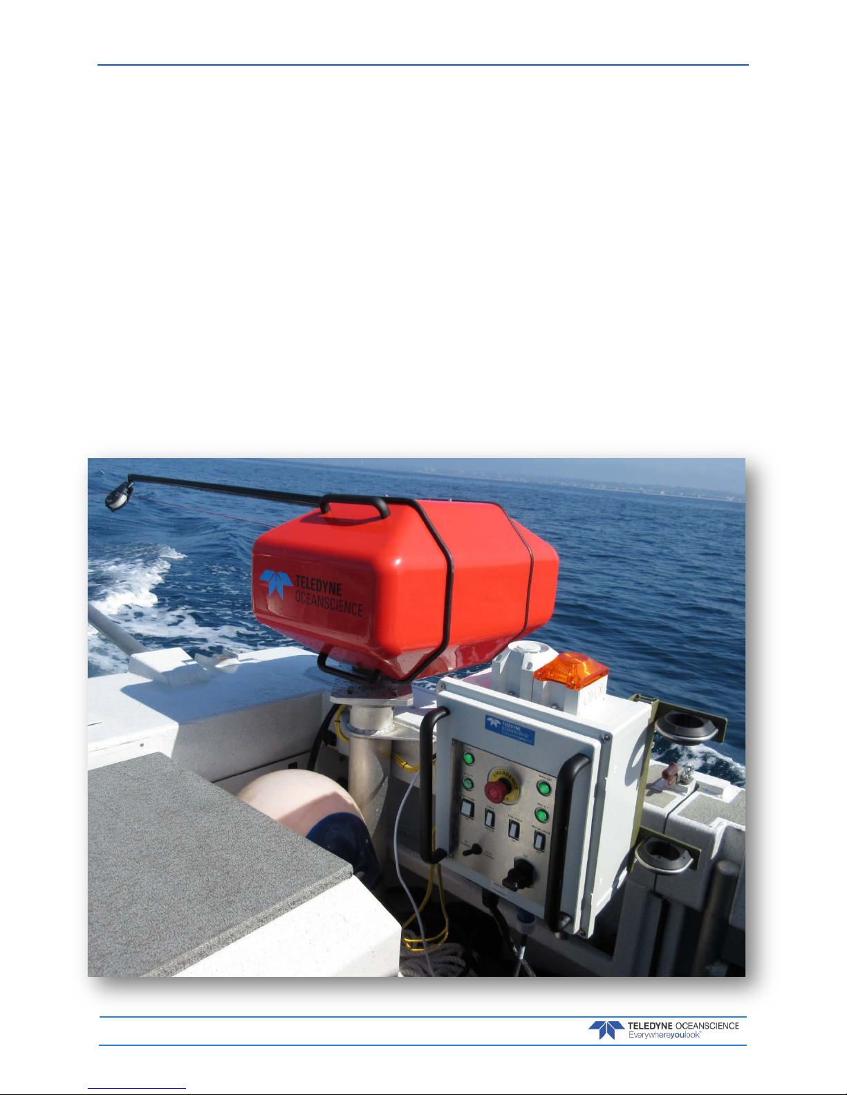
The rapidCAST delivers a probe to a user-specified target depth while the vessel is underway, and re-
trieves the probe automatically. Using an entirely new active tension management system, payout behav-
ior is precisely controlled to ensure the probe depth is known at all times - even without a conducting ca-
ble! Data transfer is achieved using an automated Bluetooth connection.
rapidCAST provides:
•A Tension Control System that allows the probe to fall freely under the influence of gravity
even when the probe is tethered to the winch.
•Line tension is measured in real-time, and the rotation speed of the spool is quickly modulated
to minimize tugging on the probe.
•If tension rises above the setpoint, the spool speeds up, and if tension falls below the setpoint,
the spool slows down until equilibrium is restored.
•The Tension Control System prevents the ship from dragging the probe, and ensures that the
probe falls freely despite surface disturbances such as waves, swells, heaving, pitching, and roll-
ing.

rapidCAST User’s Guide March 2018
EAR-Controlled Technology Subject to Restrictions Contained on the Cover Page. Page 3
rapidCAST Overview
THE RAPIDCAST OVERVIEW INCLUDES THE FOLLOWING:
Terminology
Mechanical Requirements
Electrical Requirements
Performance Specifications and Operational Limits
COMM
LaunchRecovery
March 2018 rapidCAST User’s Guide
Page 4EAR-Controlled Technology Subject to Restrictions Contained on the Cover Page.
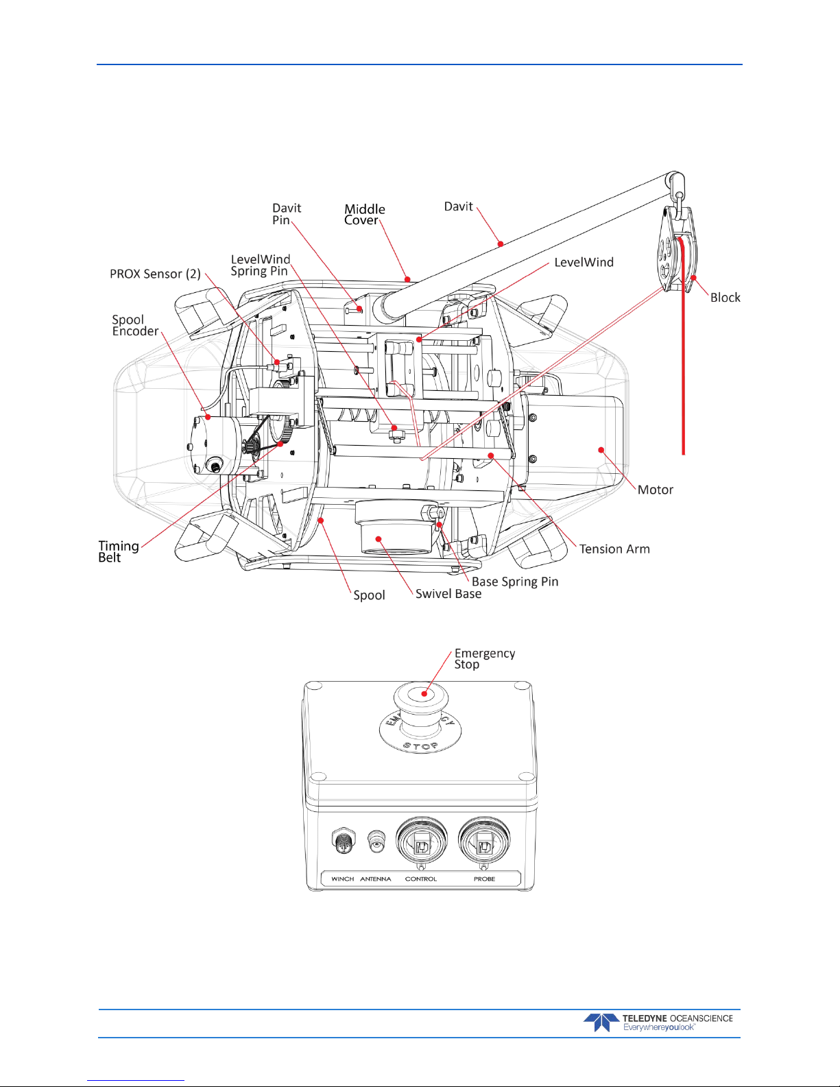
Terminology
Use this section to learn the terms that will be used throughout the manual.
Figure 1. Winch Assembly Overview
Figure 2. Interface Module Overview
rapidCAST User’s Guide March 2018
EAR-Controlled Technology Subject to Restrictions Contained on the Cover Page. Page 5
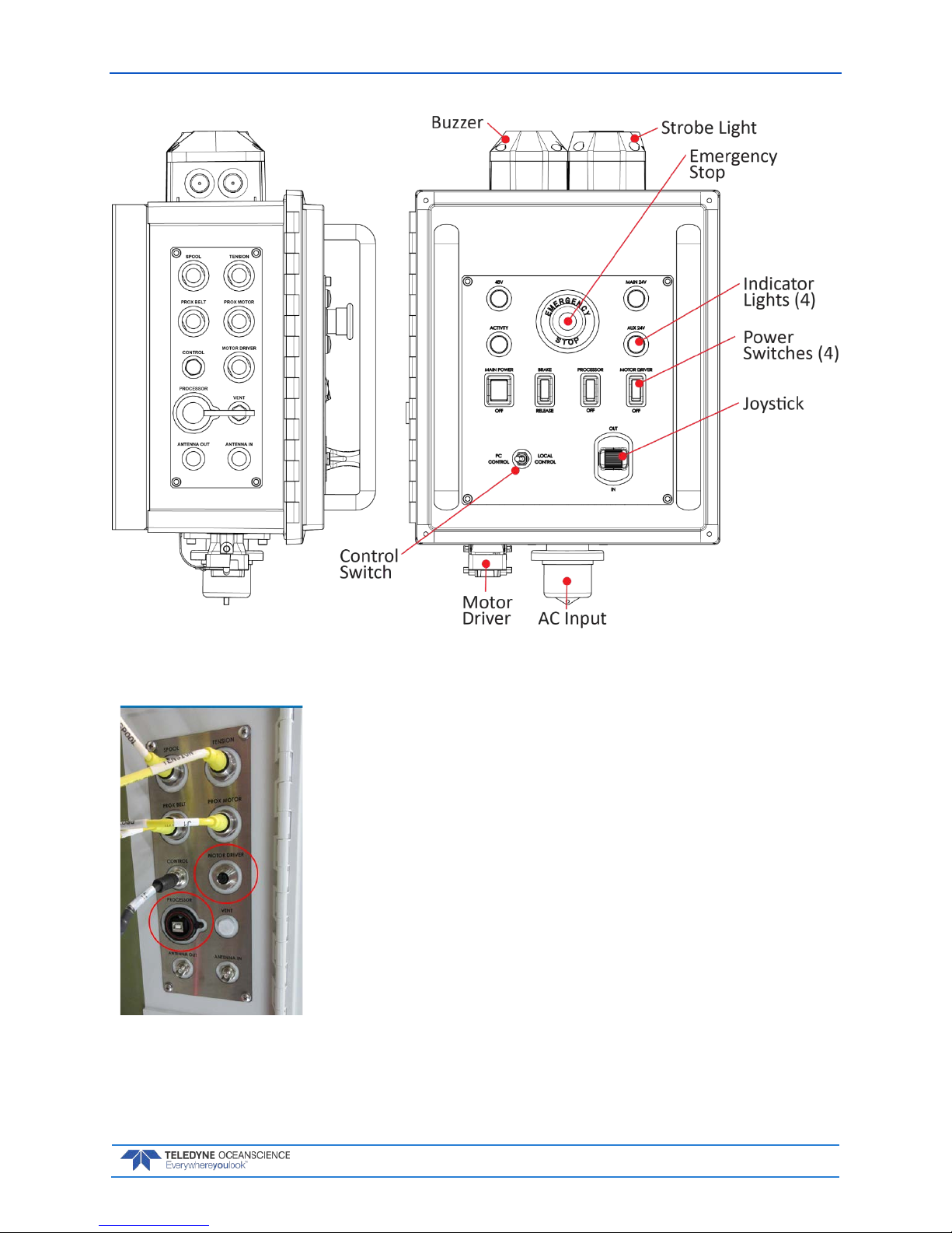
Figure 3. Control Module Overview
•The top four connectors are latching non-threaded push-pull
types.
•The Control and Antenna connectors are threaded and screw
on.
•Ensure that connectors are fully-seated; otherwise water re-
sistance may be compromised!
•Connectors circled in red are used only in special circum-
stances and are normally left disconnected. Make sure the
caps are on during a deployment to protect the connectors.

March 2018 rapidCAST User’s Guide
Page 6EAR-Controlled Technology Subject to Restrictions Contained on the Cover Page.
Figure 4. Probe Assembly Overview
Mechanical Requirements
Mounting Requirements: The ideal deployment location is in the center of the vessel, with deploy-
ment directly over the aft rail, but other locations may be possible. The swivel base should be mounted
within 24 inches of the aft rail. Oceanscience can provide designs for mounting options if necessary. In-
stallation of a serial cable running from the rapidCAST electronic control module to the survey PC is re-
quired. As the probe uses wireless Bluetooth telemetry, no cabling is required for data download.
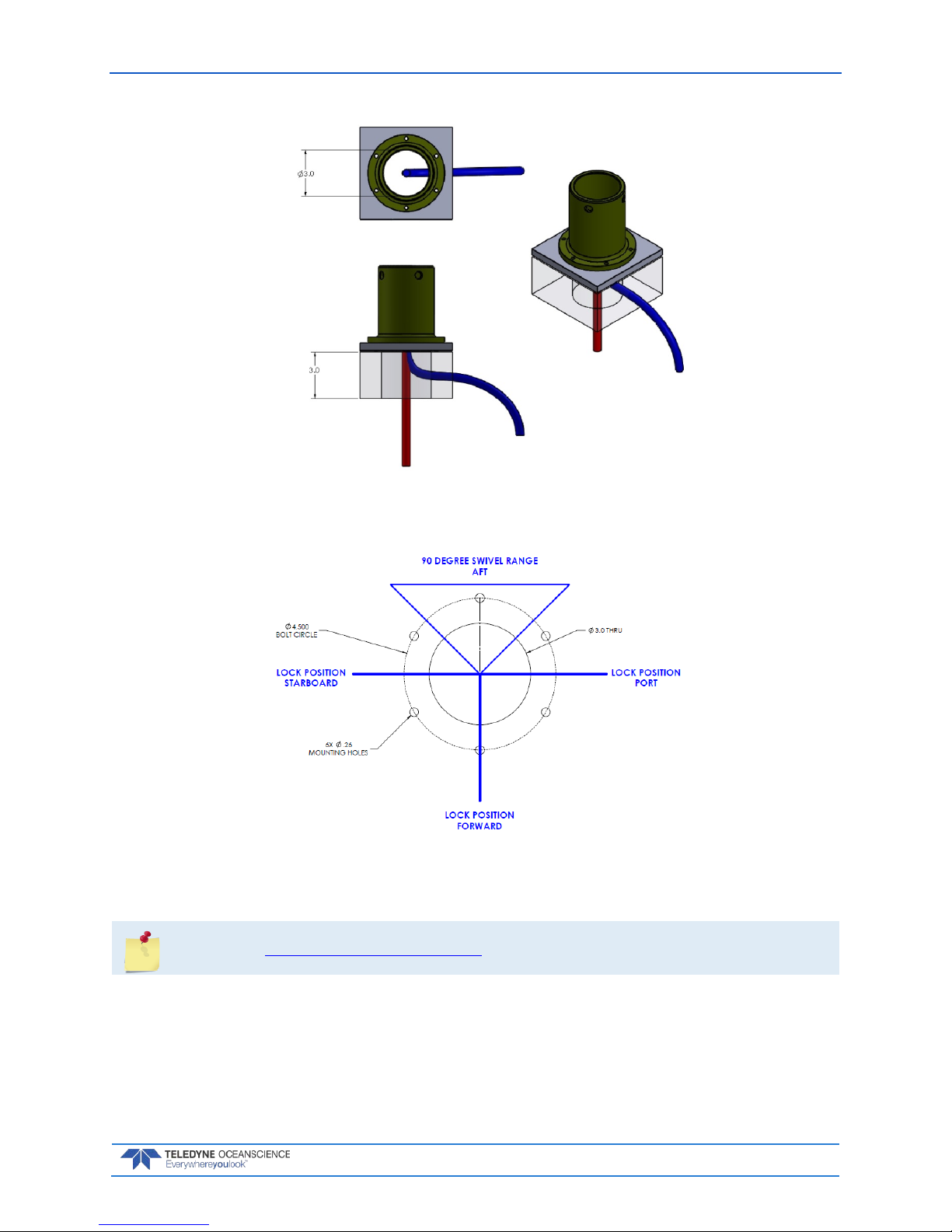
The figure below depicts mounting and cable clearance requirements. Routing of the winch power and
data cables must be taken into consideration. The bolt circle should be oriented as shown below because
the swivel base has built in stops to control the rotation of the winch, see Figure 6. The mounting platform
should be able to withstand a moment of 70ft-lbs with little to no deflection. Below the mounting plat-
form, a 3.0 inch clearance is required for cable routing. Straight down cable routing is shown in RED.
Sideways cable routing is also possible if there is a minimum 3.0 inch clearance, shown in BLUE.
rapidCAST User’s Guide March 2018
EAR-Controlled Technology Subject to Restrictions Contained on the Cover Page. Page 7
Figure 5. Cable Clearance Requirements
Figure 6. Mounting Requirements
See Appendix A - Installation Drawings for a detailed Pipe Mount Installation Drawing.

March 2018 rapidCAST User’s Guide
Page 8EAR-Controlled Technology Subject to Restrictions Contained on the Cover Page.
Profiling Depth: The nominal specification is 500m at 8kts, which requires ~1500m of line. As the ves-
sel speed decreases, the achievable cast depth increases up to the maximum pressure rating of the probe
for long stationary casts. As very deep casts are much longer in duration, the vessel cannot be moving ap-
preciably as this will waste available line to account for the movement of the ship. As the vessel speed in-
creases above 8kts, the achievable depth decreases to maintain the profiler in a safe condition during re-
covery (low line tension). The maximum vessel speed under normal operation is 12kts. The motor rpm
and braking time may be adjusted by the user to suit the survey conditions.
As long as the vessel retains a nominal forward motion to prevent entangling of the line in the ship propel-
ler. The maximum profile depth is then limited by the amount of line on the rapidCAST spool and the
probe pressure rating of 2000m.
Line Type: Hollow Spectra line of 500lb breaking strength with an 800lb leader.
Line Length: The maximum amount of line that can be loaded is about 3000m. Typically, 1500m is
used. Line length does not directly correlate to maximum cast depth underway. This depends on ship
speed because the total line paid out is a product of ship movement and probe depth.
Electrical Requirements
Input Voltage: 90 — 264 VAC RMS, Single Phase
Input Frequency 47 — 63 Hz
Max Current (at 115 VAC Input): 16 A
Max Current (at 230 VAC Input): 10 A
Inrush Current (Cold Start): 50 A Typical
Power Connectors
The rapidCAST system ships with 2 power cables, offering flexibility in the connectors used for power.
•Part Number 7000625 - 100-ft Power Cable Terminated with IEC 60309 250V 16A, 6H, Blue
P+N+E Plug, that mates to IEC 60309 250V 16A, 6H, Blue P+N+E Socket
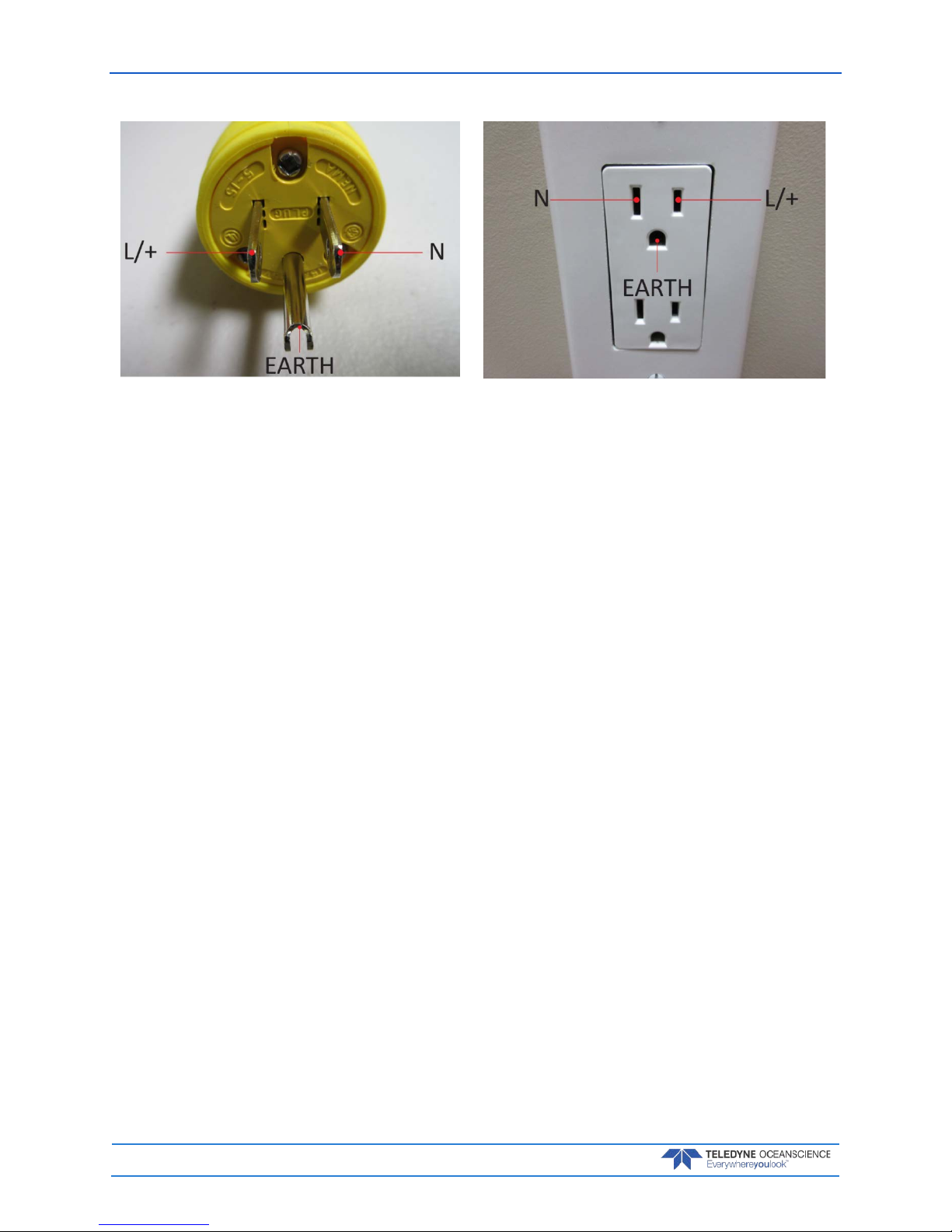
•Part Number 7000652 - 5-ft Cable Adapter Terminated with NEMA 5-15P Plug, that mates to
NEMA 5-15R Receptacle

rapidCAST User’s Guide March 2018
EAR-Controlled Technology Subject to Restrictions Contained on the Cover Page. Page 9
Power Cable Connections
The diagram below shows how the power cables may be connected.
Figure 7. Power Cable Connections
Figure 8. 7000625 Cable Plug/Termina-
tion
Figure 9. 60309 Vessel Socket / Recepta-
cle/ Outlet
March 2018 rapidCAST User’s Guide
Page 10 EAR-Controlled Technology Subject to Restrictions Contained on the Cover Page.
Figure 10. 7000652 Cable Plug/Termination Figure 11. Vessel Socket/Receptacle/Outlet

rapidCAST User’s Guide March 2018
EAR-Controlled Technology Subject to Restrictions Contained on the Cover Page. Page 11
Performance Specifications and Operational
Limits
Winch Length 48cm (18.89”)
Length with Davit 200cm (78.74”)
Width 71cm (27.95”)
Height 46cm (18.11”)
Weight 36kg (79.36 lbs.)
Input Voltage 48 VDC/ 2.0 kW
Line Capacity 3000m
Construction Aluminum/Delrin/Titanium/Stainless Steel
Probe Recovery Speed 0.5-2m/s (1.5-6.6 fps)
Mount Swivel base (12cm diameter)
Hardware Stainless Steel
Control Module Weight 14kg (30.86 lbs.)
Length 52cm (20.47”)
Width 34cm (13.34”)
Height 29cm (11.42”)
Input Power 90-264 VAC (47-63 Hz)
Output Power 48 VDC
Davit Length 160cm (63”)
Diameter 5cm (2”)
Weight 1.18kg (2.6 lbs.)
Valeport rapidSV Probe Length (with tail spool) 111cm (43.70”)
Diameter 5cm (1.96”)
Weight (in air) (without tail spool) 4.48kg (9.87 lbs.)
Internal Memory 1000 casts
Depth Rating 2000m
Pressure Resolution ±0.001% range
Accuracy ±0.05% range
Range 0-200 dBar
Temperature (if fitted) Resolution 0.001C
Accuracy ±0.01C
Range -5 to 35C
Sound Velocity Resolution 0.001m/s
Accuracy ±0.02m/s
Range 1375 - 1900m/s
Profiling Capability >500 m at 5 kts or deeper at slow speeds
(see Table 1, page 12)
March 2018 rapidCAST User’s Guide
Page 12 EAR-Controlled Technology Subject to Restrictions Contained on the Cover Page.
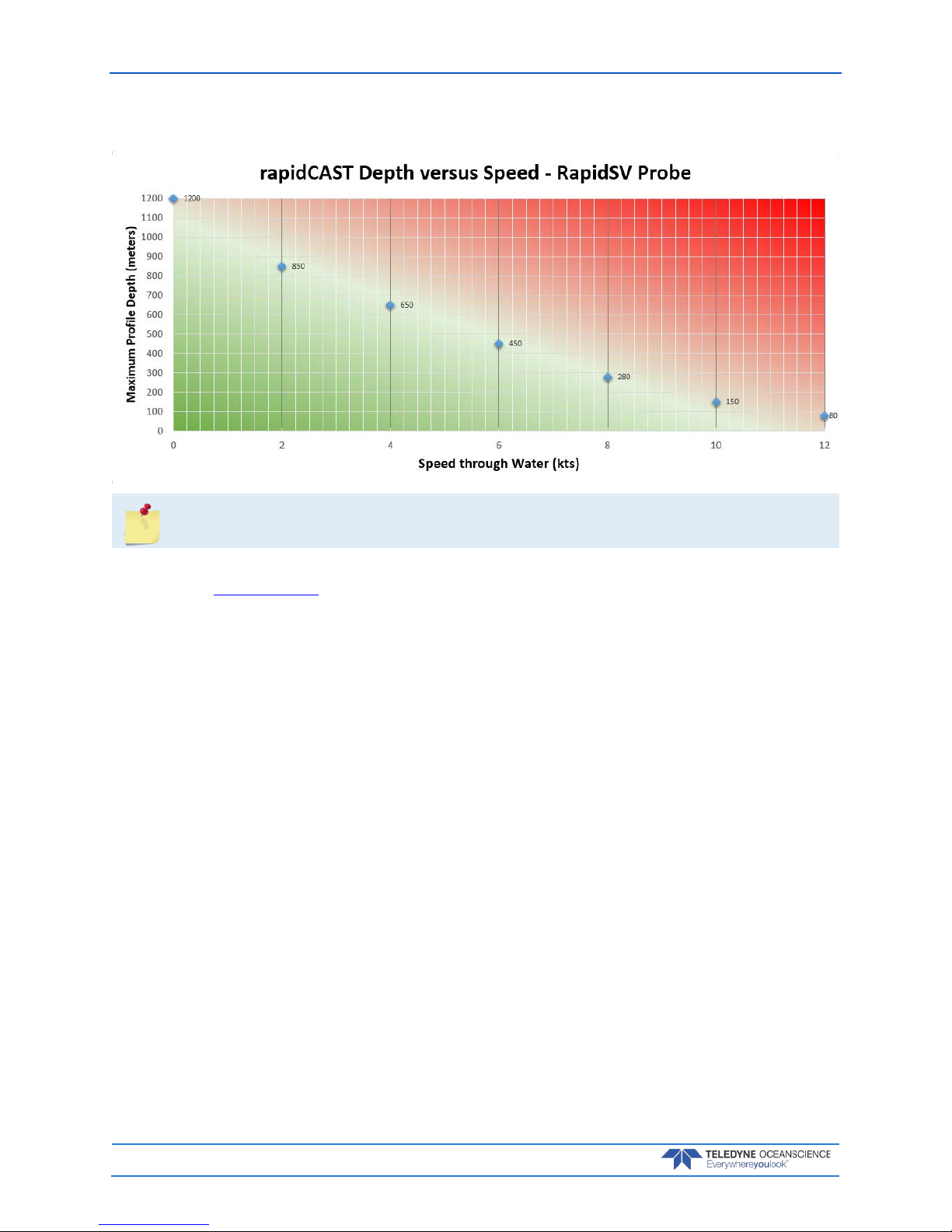
Table 1. rapidCAST Depth versus Speed
The table above applies to the RapidSV probe. Call for details on other probes.
Each standard spool is delivered with 1954 meters of line, of which 1700 meters can be used for normal
operation (see Line Properties, page 30). Typically, only 1200 meters of line are used.
Deployments less than 100 meters deep:
•The buoyancy tailspool can be used. In this configuration, the probe will fall at approximately
3 m/sec.
The following general specification applies:
•Boat speed relative
Deployment greater than 100 meters deep:
•The buoyancy tailspool CANOT be used. In this configuration use the plain tailspool, the probe
will fall at approximately 4 m/sec.

rapidCAST User’s Guide March 2018
EAR-Controlled Technology Subject to Restrictions Contained on the Cover Page. Page 13
Quick Review
Check that you know the
Terminology used.
Reference Figure 1 through
Figure 4.
Check that the boat meets
the Mechanical and
Electrical Requirements
Reference page 6 to 8.

March 2018 rapidCAST User’s Guide
Page 14 EAR-Controlled Technology Subject to Restrictions Contained on the Cover Page.
Installation
INSTALLATION INCLUDES THE FOLLOWING STEPS:
Unpacking the rapidCAST system
Installing the RapidCAST Control Software
Learning Cable Connections and Switch Functions
Mounting the Winch
Verifying Probe Communications
COMM
LaunchRecovery
Table of contents


