TELEDYNE OLDHAM SIMTRONICS Everywhereyoulook MultiFlame DF-TV7 User manual
NOSP17662-Revision 03
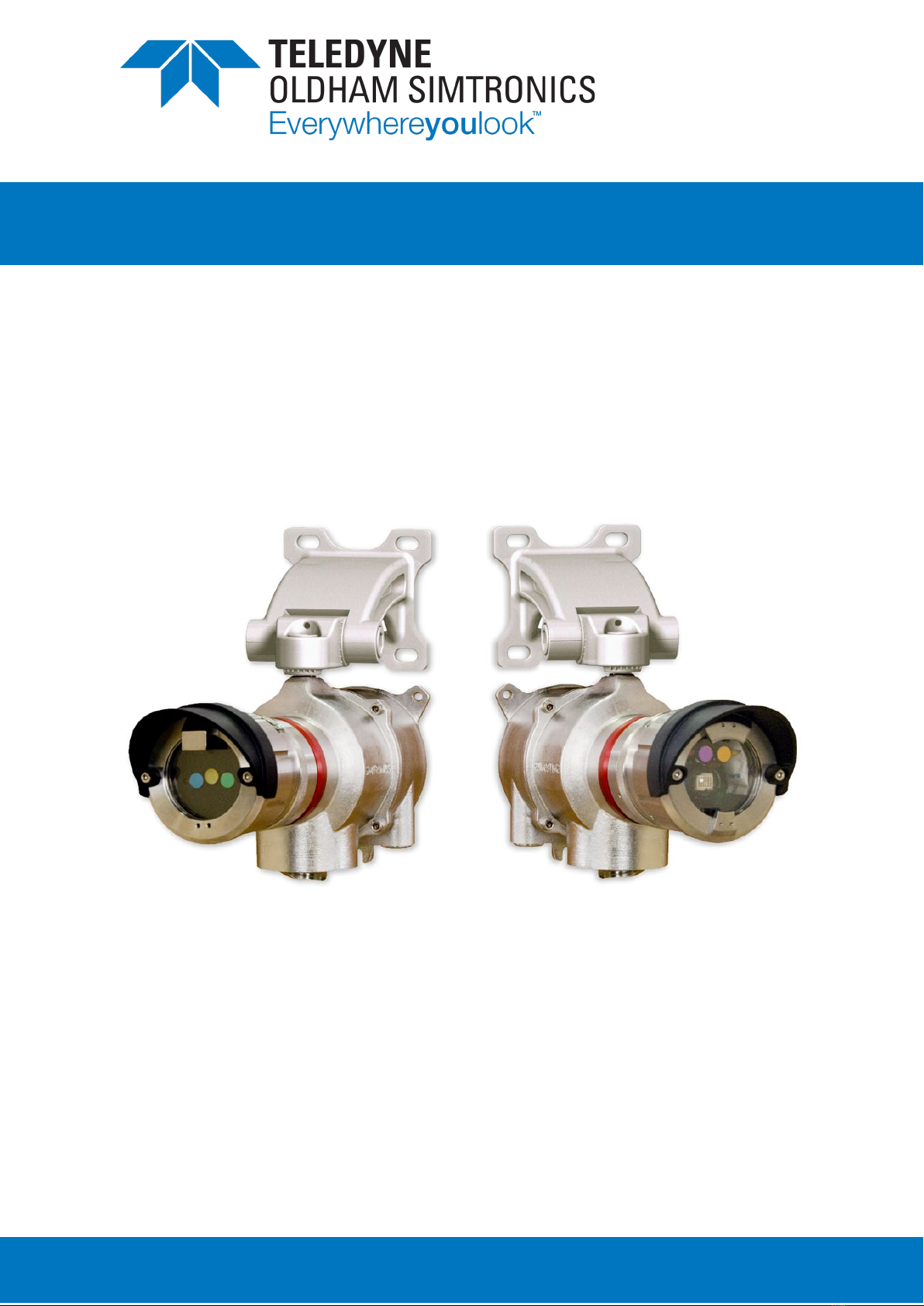
MULTIFLAME DF-TV7
OPTICAL FLAME DETECTOR
DF-TV7-T Multi-spectrum IR
DF-TV7-V Combined UV/IR
(with Magnetic interface)
OPERATING
MANUAL

MULTIFLAME DF-TV7
OPTICAL FLAME DETECTOR
USER MANUAL
II
NOSP17662
Revision 03
User Manuals in other languages are available on
Website https://teledynegasandflamedetection.com
Copyright March 2021 by TELEDYNE OLDHAM SIMTRONICS S.A.S.
All rights reserved. No reproduction of all or part of this document, in any form, is permitted
without the written consent of TELEDYNE OLDHAM SIMTRONICS S.A.S.
All of the information that is provided in this document is accurate to the best of our knowledge.
As a result of continuous research and development, the specifications of this product may be
changed without prior notice.
TELEDYNE OLDHAM SIMTRONICS S.A.S.
Rue Orfila
Z.I. Est – CS 20417
62027 ARRAS Cedex

MULTIFLAME DF-TV7
OPTICAL FLAME DETECTOR
OPERATING MANUAL
NOSP17662
Revision 03
III
Limitation of Liability
The Company TELEDYNE OLDHAM SIMTRONICS S.A.S., hereinafter referred to as “TELEDYNE
OLDHAM SIMTRONICS” throughout this document, shall not be held responsible for any
damage to the equipment or for any physical injury or death resulting in whole or in part from the
inappropriate use or installation of the equipment, non-compliance with any and all instructions,
warnings, standards and/or regulations in force.
No business, person or legal entity may assume responsibility on behalf of TELEDYNE OLDHAM
SIMTRONICS, even though they may be involved in the sale of TELEDYNE OLDHAM
SIMTRONICS products.
TELEDYNE OLDHAM SIMTRONICS shall not be responsible for any direct or indirect damage,
or any direct or indirect consequence, resulting from the sale and use of any of its products
UNLESS SUCH PRODUCTS HAVE BEEN SELECTED BY TELEDYNE OLDHAM SIMTRONICS
ACCORDING TO THE APPLICATION.
Ownership clauses
The drawings, specifications, and information herein contain confidential information that is the
property of TELEDYNE OLDHAM SIMTRONICS.
This information shall not, either in whole or in part, by physical, electronic, or any other means
whatsoever, be reproduced, copied, divulged, translated, or used as the basis for the
manufacture or sale of TELEDYNE OLDHAM SIMTRONICS equipment, or for any other reason
without the prior consent of TELEDYNE OLDHAM SIMTRONICS.
Warning
This is not a contractual document. In the best interest of its customers and with the aim of
improving performance, TELEDYNE OLDHAM SIMTRONICS reserves the right to alter the
technical features of its equipment without prior notice.
READ THESE INSTRUCTIONS CAREFULLY BEFORE THE FIRST USAGE: these instructions
should be read by all persons who have or will have responsibility for the use, maintenance, or
repair of the instrument.
This instrument shall only be deemed to be in conformance with the published performance if
used, maintained, and repaired in accordance with the instructions of TELEDYNE OLDHAM
SIMTRONICS by TELEDYNE OLDHAM SIMTRONICS personnel or by personnel authorized by
TELEDYNE OLDHAM SIMTRONICS.

MULTIFLAME DF-TV7
OPTICAL FLAME DETECTOR
OPERATING MANUAL
IV
NOSP17662
Revision 03
Important Information
The modification of the material and the use of parts of an unspecified origin shall entail the
cancellation of any form of warranty.
The use of the unit has been projected for the applications specified in the technical
characteristics. Exceeding the indicated values cannot in any case be authorized.
TELEDYNE OLDHAM SIMTRONICS recommends regular testing of fixed gas detection
installations (read Chapter 7).
Warranty
Under normal conditions of use and on return to the factory, DF-TV7 flame detectors carry a 3-
year warranty on IR models and 2 years on combined UV/2IR models, excluding accessories
such as tilt mount, weather protection, etc.
Waste Electrical and Electronic Equipment (WEEE
directive)
European Union (and EEA) only. This symbol indicates that, in conformity with directive
DEEE (2002/96/CE) and according to local regulations, this product may not be
discarded together with household waste.
It must be disposed of in a collection area that is set aside for this purpose, for example at a site
that is officially designated for the recycling of electrical and electronic equipment (EEE) or a
point of exchange for authorized products in the event of the acquisition of a new product of the
same type as before.

MULTIFLAME DF-TV7
OPTICAL FLAME DETECTOR
OPERATING MANUAL
NOSP17662
Revision 03
V
Table of Contents
1Product Description.......................................................................... 1
1.1 Applications.........................................................................................................1
1.2 DF-TV7-T: multi-spectrum IR............................................................................2
1.3DF-TV7-V: combined UV and IR ...................................................................2
1.4 Technical specifications .................................................................................2
1.5 Detection Cartridge.........................................................................................3
1.6 Optical self-test function ................................................................................4
1.7 Communication Interface.............................................................................4
1.8 Product Code.....................................................................................................6
2Technical features............................................................................ 7
3Performances .................................................................................... 11
3.1 Sensitivity...............................................................................................................11
3.2 Field of View (Cone of Vision) ......................................................................12
3.3 False alarm immunity (FM 3260) ..................................................................13
4Installation .......................................................................................... 15
4.1 Location ................................................................................................................15
4.2 Mounting...............................................................................................................16
4.3 Electric Connection..........................................................................................19
4.4 Detection cartridge..........................................................................................25
5Commissioning.................................................................................. 29
5.1 Visual inspection ................................................................................................29
5.2 Power-up...............................................................................................................29
5.3 Operational tests ...............................................................................................29
5.4 Using the LT15 test lamp..................................................................................30
6Operation ........................................................................................... 31
6.1 Environmental conditions...............................................................................31
6.2 Inhibition................................................................................................................31
6.3 Signal current loop............................................................................................32

MULTIFLAME DF-TV7
OPTICAL FLAME DETECTOR
OPERATING MANUAL
VI
NOSP17662
Revision 03
6.4 Power and fault indications ..........................................................................33
6.5 Alarm indication (LED).....................................................................................33
6.6 Wireless communication tool TLU600.........................................................34
6.7 Information menu [INFO]................................................................................37
6.8 Adjustment menu [ADJT]................................................................................38
6.9 The maintenance menu [MAIN]..................................................................41
6.10 Magnets Operation..........................................................................................42
7Maintenance ..................................................................................... 45
7.1 Periodic maintenance ....................................................................................45
7.2 List of main faults................................................................................................46
7.3 Replacing the cartridge .................................................................................47
7.4 Replacing the complete detector.............................................................47
8Certifications and standards ......................................................... 48
8.1 Functional Safety...............................................................................................48
8.2 ATEX / IECEx Marking........................................................................................48
9Accessories and spare parts......................................................... 51
9.1 Accessories ..........................................................................................................51
9.2 Spare parts...........................................................................................................52
10 Conformity certificate ..................................................................... 53

MULTIFLAME DF-TV7
OPTICAL FLAME DETECTOR
OPERATING MANUAL
NOSP17662
Revision 03
1
1Product Description
MultiFlame DF-TV7-T was designed to detect hydrocarbon fires, while minimizing false alarms.
This detector is equipped with an intelligent optical self-test. It is certified and may be installed in
SIL2 level system. It can be directly connected to a wide range of traditional or fire controllers
and on Programmable Logic Controllers (PLC).
DF-TV7-T can be fully configured using the portable communication terminal (TLU600), providing
flexibility to the user. Time delay, sensitivity and outputs configuration can be full set up via the
TLU600, a hazardous area approved remote control. Optical and electronic parts, and outputs
(current, relay…) of the detector can be controlled by the TLU. The DF-TV7-T can be configured
too by the HART communication terminal, TLH700 (in option).
Concerning to the Type-D detector, some operations can be done with the magnetic wand
(CEDPC led, flame simulation, LT15 test)
The MultiFlame product family consists of two detector versions:
•DF-TV7-T multi-spectrum IR Flame detector
•DF-TV7-V combined UV and IR
The MultiFlame models are also available for use in an addressable network system with
distributed intelligence SYNTEL. This version is named DF-RV7-*. For more information, please
refer to the Syntel module interface operating manual.
1.1 Applications
•Refineries
•Drilling and Production Platforms
•FPSO
•Fuel Loading Facilities
•Compressor Stations
•LNG/LPG Processing and Storage
•Gas Turbines
•Chemical Plants
•Aircraft Hangars
•Sports (Stadia / Gymnasia)
The sensitivity of flame detector depends on many factors including, fuel type, fire size,
atmospheric conditions (wind, rain, fog, etc...), the angle between the fire and detector as well
as line of sight obstructions.
MULTIFLAME DF-TV7
OPTICAL FLAME DETECTOR
OPERATING MANUAL
2
NOSP17662
Revision 03
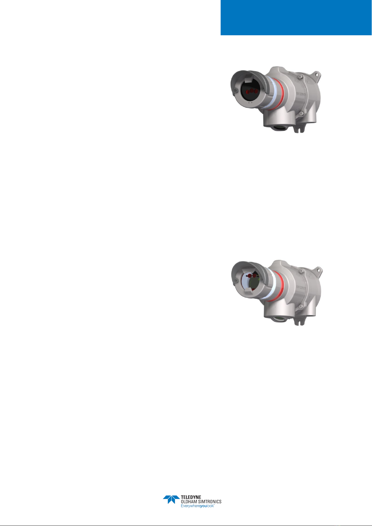
1.2 DF-TV7-T: multi-spectrum IR
The DF-TV7-T is a multi-spectrum flame detector using
three individual infrared wavelengths. The use of three
different IR bands and a unique signal processing
algorithm allows excellent flame detection performances,
while offering a very low rate of false alarms.
The detector can be supplied with a configurable
cartridge:
•A "standard range" sensor cartridge covering most applications
•A “high sensitivity" sensor cartridge for special applications where the maximum sensitivity
is required.
1.3 DF-TV7-V: combined UV and IR
Designed to cover a large detection range while ensuring excellent immunity against false alarms,
the DF-TV7-V is the alternative when multi-spectrum IR cannot be used.
False alarms are minimized using two infrared wavelengths plus a fast-acting UV wavelength to
confirm detection. This version is useful in difficult environmental conditions, such as combined
rain and wind, rapid sunshine variations, hot sources modulations, industrial lighting etc.
The DF-TV7-V is also configurable for special applications,
where using just dual IR or just direct UV detection is
required.
The UV detector can be sensitive to UV welding radiation or
lightning, X rays and gamma rays.
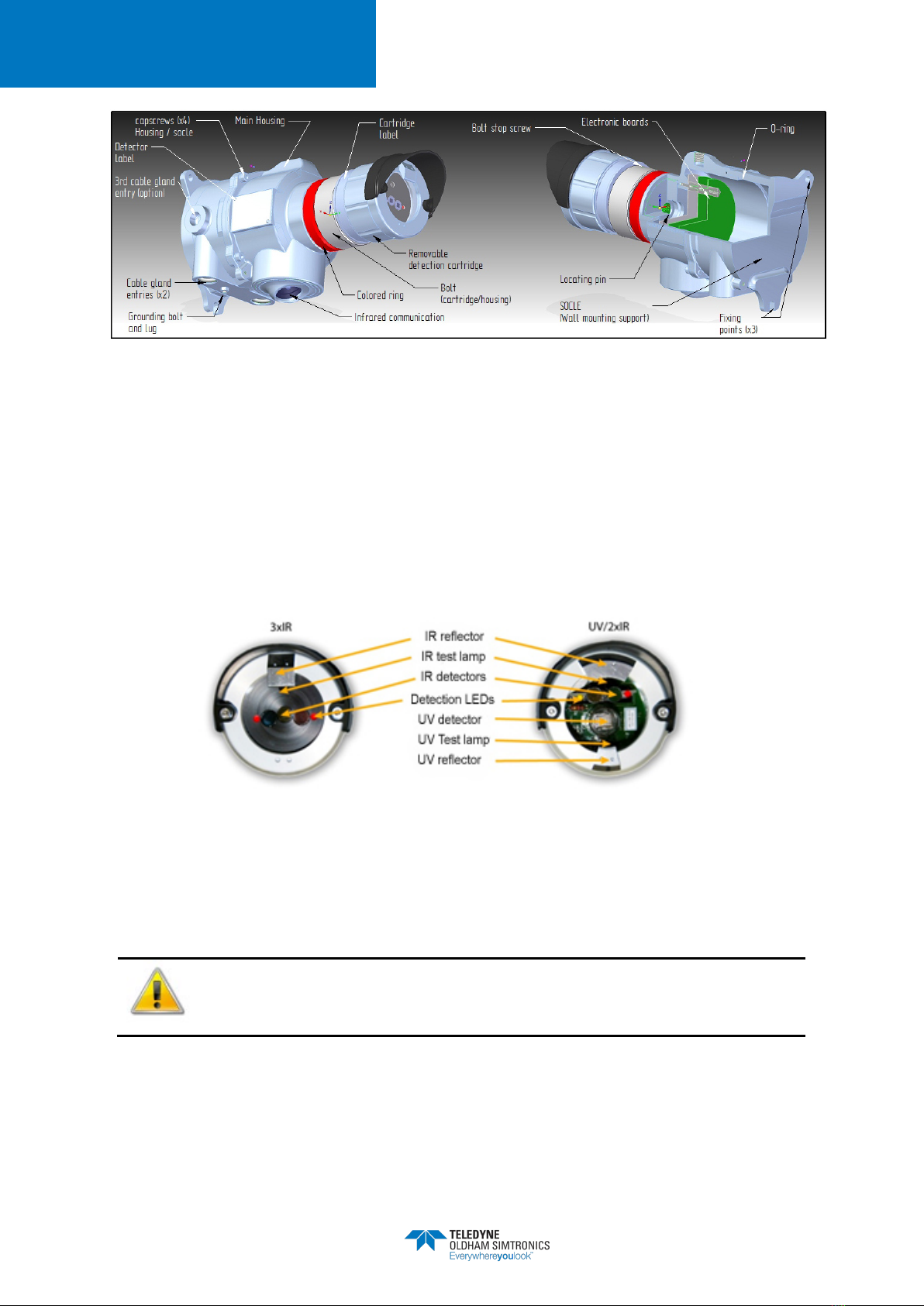
1.4 Technical specifications
Each detector is constructed as follows:
•A wall-mounted support secured by three screws and including cable gland (M20)
(optional). There are 2 standard entries and an optional one.
•A stainless steel (316L) explosion-proof housing containing a set of tropicalized electronic
cards
•The sensor cartridge contains the flame detection circuitry. So, it is possible to change the
cartridge easily. The multi-spectrum IR detector is also available in a high sensitivity
version.
•An IR communication head is located below the detector housing. It is used for
communication with the maintenance hand-held terminal (TLU).
•A metallic support cable (optional) connects the wall mounting support and the housing,
making the maintenance easier.
MULTIFLAME DF-TV7
OPTICAL FLAME DETECTOR
OPERATING MANUAL
NOSP17662
Revision 03
3
Figure 1 : Detector presentation
(Overall dimension drawings, see Figure 2)
1.5 Detection Cartridge
Cartridges are explosion proof designed. They are common to all MultiFlame line of products in
order to reduce spares parts.
•DF-RV7-T and DF-RV7-V: Network “Telecaptor” flame detector line,
•DF-TV7-T and DF-TV7-V: “Telecaptor” flame detector line.
When in fire alarm mode, the red LED located in the communication head and the two LEDs
located in front of the detection cartridge are blinking. Information and detector status is also
available via the remote control TLU 600 / TLH700 display.
The cartridge must not be removed when the detector is powered.

MULTIFLAME DF-TV7
OPTICAL FLAME DETECTOR
OPERATING MANUAL
4
NOSP17662
Revision 03
1.6 Optical self-test function
Sensor cartridges have one or more self-test optical lamps allowing detection integrity test. This is
a full optical test where the signal from each test lamp is transmitted through the sensor window
and reflected back to the detecting elements via a polished stainless-steel reflector.
In addition to this cyclic self-test, the test lamps can be used when a "flame simulation test" is
initiated by the maintenance terminal. Further testing is not required to confirm correct operation.
As part of the continuous improvement of our products, we are gradually implementing a new
source of IR self-test whose reliability and repeatability are reinforced to the current version.
However, you will notice that the signal is now invisible to the eye, all the energy dissipated is
limited to the useful infrared band. It is therefore no longer possible to distinguish the lamp
illumination from the correct operation of the measurement chain.
It should be noted that a malfunction of one of them is extremely improbable. Indeed, the
lifetime expected for this source is much longer than 5 years.
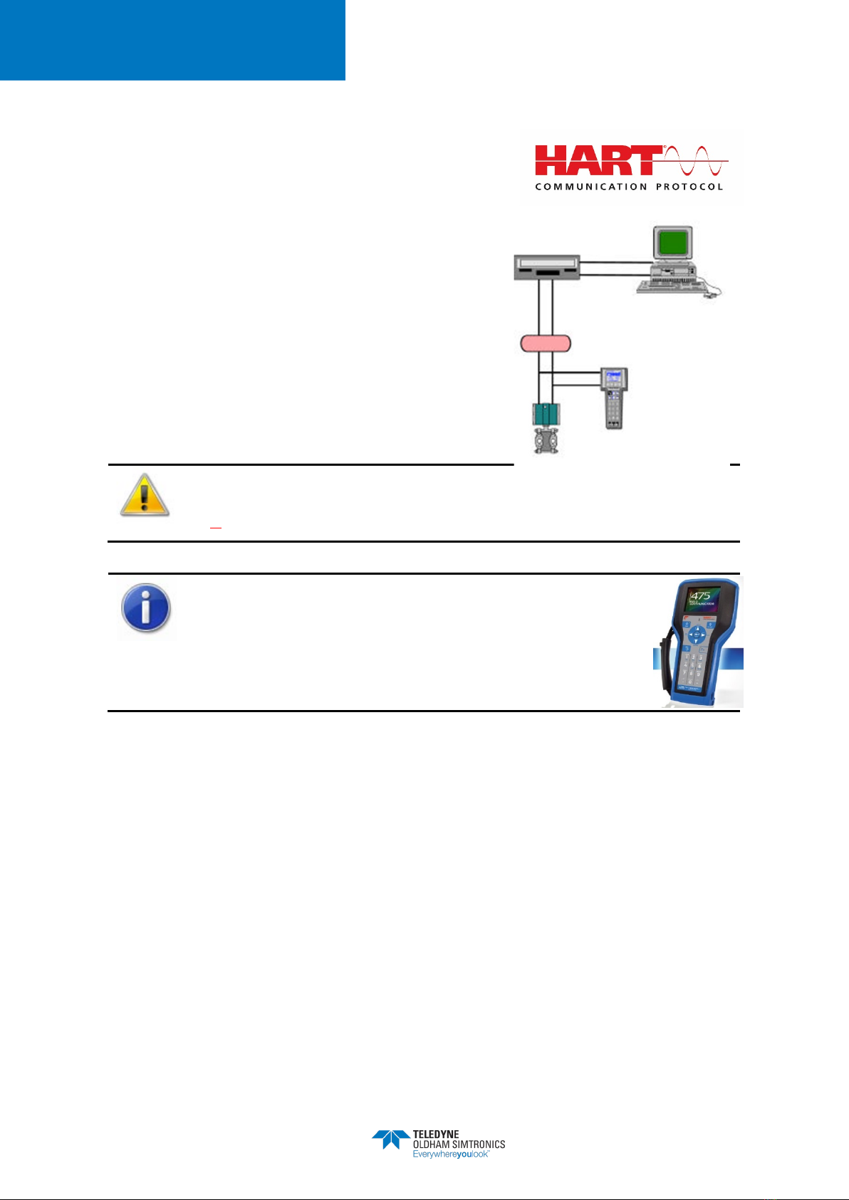
1.7 Communication Interface
1.7.1 Wireless Configuration Tool
Information and status of the detector are available via the wireless
configuration tool TLU600.
Configuration and tests are performed using this wireless configuration
tool (IrDA protocol). This tool is common for all TELEDYNE OLDHAM
SIMTRONICS MultiFlame, MultiXplo and MultiTox products.
The TLU600 provides access to devices which, otherwise, would require major logistic operations
for maintenance or for configuration (calibration …).
For more details, please refer to the wireless configuration tool operating manual.
1.7.2 Magnetic wand
The Type-D electronic version includes two magnetic sensors PG1 and PG2 implanted on the
numeric card.
The communication interface is a magnetic wand.The wand can be used only to acess to the
following functions :
•Alarms acknolodwment
•CEDP led
•Flame simulation
•LT15 mode
MULTIFLAME DF-TV7
OPTICAL FLAME DETECTOR
OPERATING MANUAL
NOSP17662
Revision 03
5
1.7.3 HART communication
The HART communication authorizes an addressing of
devices, allowing the communication in read/write mode.
It consists in getting connection on the current loop on which
the numerical data are superimposed.
Most of the HART terminal can read this information and
send commands
The use of a DD (Device Descriptor) facilitates the interface
Man-Device. It can be uploaded on our website.
HART protocol is optional. Read the P/N on your detector and check it contains
the letter ‘H’ at the 12th position for HART compatibility. P/N:
DF
-TV7-****-
**H-**-***-*-*-*
TELEDYNE OLDHAM SIMTRONICS devices under HART
protocol enable the use of all the functions available with the
TLU600 via the HART terminal
Read document P/N D1401002 for Hart Terminal TLH700 operation (Device Descriptor file
must be downloaded).

MULTIFLAME DF-TV7
OPTICAL FLAME DETECTOR
OPERATING MANUAL
6
NOSP17662
Revision 03
1.8 Product Code
Product codes are created from functional codes: DF-ξV7-X#σ0-0αβ-0ρ-00ε-µ-φ-0
ξ
V
6
7
XV
XT
σ
-0
α
β
-0
ρ
-00
ε
-
µ
-
φ
-0
C** Compact capteur
T** Télécapteur
R** Capteur réseau / Network version
Famille / Families
*
V
* Flamme / Flame
Génération
**6BT606 Boitier / housing
**7BT10 Boitier / housing
Type Flamme
XV
UVIR²
XT
IR3
XW
UV
σ
0
Portée de détection
A0
Portée standard / Standard range
B0 Longue Portée (Version XT uniquement) / Long range (only XT versions)
0
Type
0**
Non utilisé ou flamme / not used or flame
α
Variante
*A*
Aluminium
*X*
SS316L
β
Interface
**
A
Protocole 0-22mA (Défaut sur le 0-4 mA/ fault on range 0-4mA )
**E
Protocole 4-20 mA (Défaut commun / Common fault signal : 2 mA)
**H
4 – 20 mA / 0-22 mA configurable & protocole HART
**C
4 – 20 mA / 0-22 mA configurable
**L
LON
0
Cartouches
0* Cartouche flamme / flame cartridge
ρ
configurations. spéciales
*0Standard
*M
Version spéciale MarED
(TX6 et TV6 type A uniquement)
*N
Version spéciale AL LED non mémorisée
(Non conforme EN 54-10) (flamme uniquement)
*1Customisation EPR (suivi spécial – SP4M20)
(DM et DMi uniquement)
0
εε
Configuration
000 Standard
**A
Exempt de toute trace de graisse /
grease free
**B
Version spéciale MarED (ancien code)
(TX6 et TV6 type A uniquement)
**C
Version non EN 54-10 (ALRM non
mémo) (type A uniquement)
**F
Certified Telecaptor instead of IRDA
**G
Peinture hydrocentrifugon (applications
nucléaire) /
Hydrocentrifugon paint
(nuclear applications)
**H Peinture light grey (10A03 selon
« British standards 4800/5252 »)
**J Peinture spéciale : RAL 3001 (Rouge)
*L*
Epaisseur peinture >200 µm (version
ATEX IIB)
µ
Langue / Language
0
Fr / GB
F
Français / French
E
Anglais / English
P
Portugais / Portuguese
C
Chinois / Chinese
Hardware version
A
Type 63
B
Type 65
C
Type 67 (HART)
D
Type 69 (magnet)
Software version
0
Standard

MULTIFLAME DF-TV7
OPTICAL FLAME DETECTOR
OPERATING MANUAL
NOSP17662
Revision 03
7
2Technical features
GENERAL
Type Optical flame detectors
DF-TV6-T Multi-spectrum IR Flame detector
DF-TV7-V Combined IR and UV detection.
Start-up time 15 secs
Self-test Automatic periodic test through the window
Calibration Factory set, no field recalibration
OUTPUT SIGNAL
4-20mA loop signal Active type (source), max. load impedance 700Ω.
"4-20mA" format 4-20mA loop with a single fault level
•Normal 4 mA
•Flame alarm 20 mA
•Fault or inhibition 1.5 mA
•Optical autotest fault 1.5, 2.0 or 3.0 mA (configured
by TLU600 / TLH700)
"0-22mA" format 4-20mA loop with multiple fault levels, suitable for PLC’s and modern
control systems.
•Normal 4 mA
•Flame alarm 20 mA
•Inhibition 3.4 mA
•Optical self-test fault 2.6 mA
•HW/SW fault 2.0 mA
Relay output 3 x configurable relays max 1.7A/30VAC/DC (in option) 1
1This value changes to 1A when the security function uses the relays and the SIL level is required

MULTIFLAME DF-TV7
OPTICAL FLAME DETECTOR
OPERATING MANUAL
8
NOSP17662
Revision 03
ELECTRICAL
Power supply 24V DC,(Range 18 – 35 V DC versions DF-T#7)
(Range 18 – 30 V DC versions DF-R#7)
Power consumption
IR3 UV2IR
Typical21.4w
network : 2.6 w
1.5 w
network : 2.7W
Maximum 5 w 5 w
Connection 0,5mm² (20AWG)-2,5mm² (13AWG)
MTBF: DF-TV7-T: 172 000 h
DF-TV7-V: 115 000 h
ENVIRONMENTAL
Temperature (Storage) -40°C to +65°C
Temperature (Operation) -40°C to +65°C
Pressure 1013 HPa ± 10%
Humidity 95% RH (non condensable)
Protection IP66
RFI/EMI Complies with EN 50130-4 (2011 AMD 2014)
PERFORMANCE
European EN 54-10/A1 (2005)
EXPLOSION PROOF HOUSING
Material 316 L stainless steel
Weight 5.1 kg
ATEX/IECEx Please refer to §8.2
2Typical power: voltage 24 Vdc, current 4 mA, fault relay normally energized.
Maximum power: voltage 35 Vdc, current 22 mA, 3 relays energized, during optical self-test.
MULTIFLAME DF-TV7
OPTICAL FLAME DETECTOR
OPERATING MANUAL
NOSP17662
Revision 03
9
FONCTIONNAL SAFETY
SIL SIL certification in progress according IEC/EN 61508 parties 1 to 7
standard
Detector
Data
Definitions
Values
current output
Value relay
output 3
Multi IR
DF-TV7-T
λFailure rate per hour 1.57x10⁻⁶/h 1.53x10⁻⁶/h
SFF Safety fraction failure
(T1=6 h)
99.2% 92.5%
PFD*
Probability of failure
on Demande 8.41x10⁻⁵ 5.39x10⁻⁴
PFH
Probability of failure /
h (1oo1) 1.23x10⁻⁸ 1.16x10⁻⁷
MTTR Mean Time To Repair 1440 min
SIL
compliance
HFT = 0 / G.Fixed /
30°C / type B 2 2
UVIR2
DF-TV7-V
λFailure rate per hour 4.13x10⁻⁶/h 4.09x10⁻⁶/h
SFF Safety fraction failure 99.6% 97.1%
PFD*
Probability of failure
on demand (T1=2.5
h)
1.56x10⁻⁴ 6.10x10⁻⁴
PFH Probability of failure /
h (1oo1)
1.44x10⁻⁸ 1.18x10⁻⁷
MTTR Mean Time To Repair 1440 min
SIL
compliance
HFT = 0 / G.Fixed /
30°C / type B 2 2
Updated SIL certificate pending. The values are given as an indication.
•*SF control periodicity : see § 7.1
•*SF control method : see §7.1.4
3When the relays are in factory configuration: refer to paragraph 8.8.3.3
MULTIFLAME DF-TV7
OPTICAL FLAME DETECTOR
OPERATING MANUAL
10
NOSP17662
Revision 03
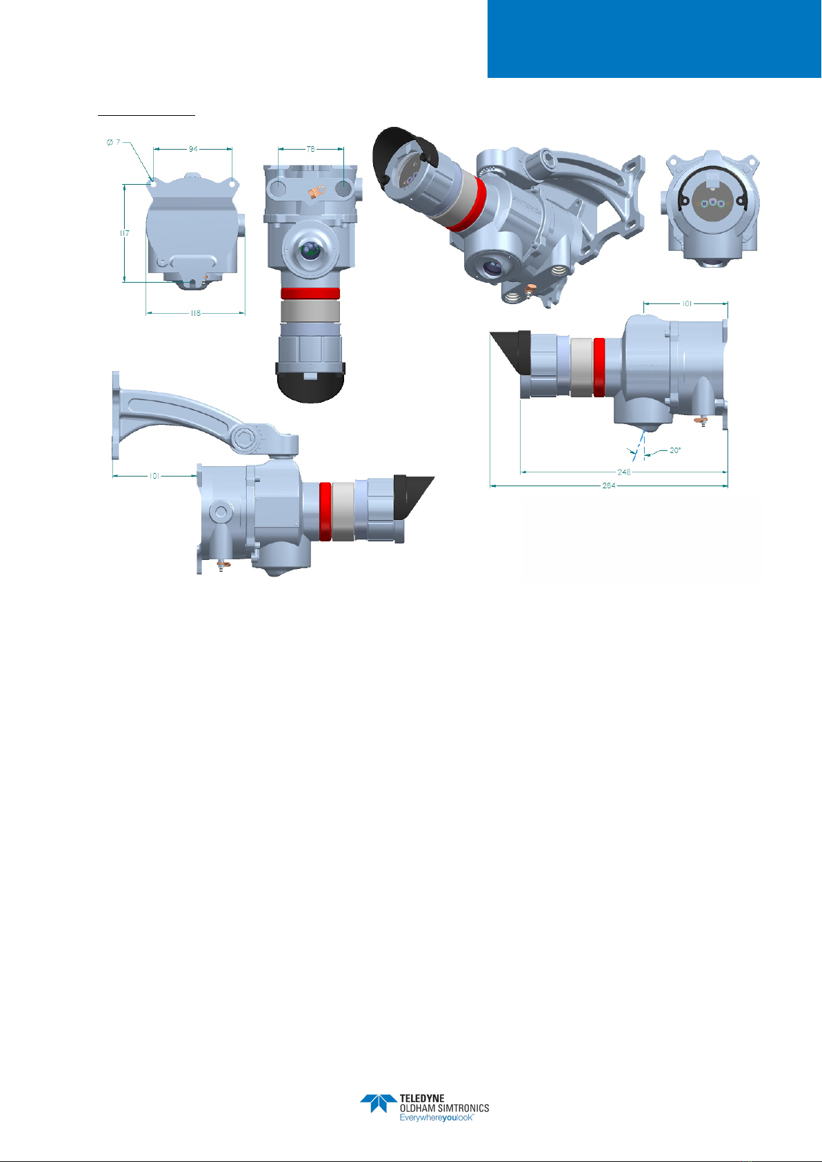
DIMENSIONS
Figure 2 : Dimension drawings

MULTIFLAME DF-TV7
OPTICAL FLAME DETECTOR
OPERATING MANUAL
NOSP17662
Revision 03
11
3Performances
3.1 Sensitivity
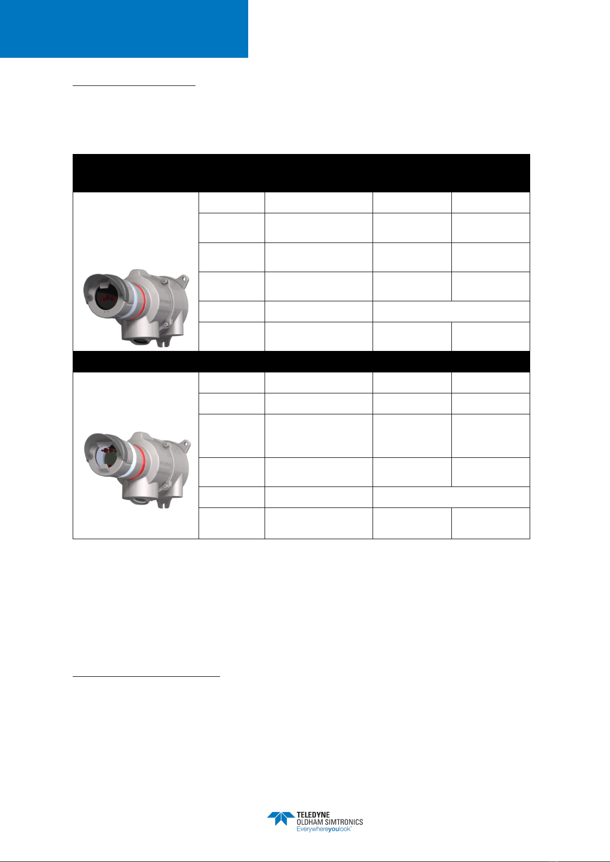
3.1.1 Fire class
Classification according to §5.5.3 – EN 54-10 (2006), (ethanol and n-heptane fires)
DF-TV7-XVA0 ET DF-TV7-XTA0
Sensitivity
Time delay
50%
75%
100%
Min
Class 2
Class 1
Class 1
Max (20 sec) Class 2 Class 2 Class 1
DF-TV7-XTB0
Class 1 for any combinations of sensitivity and time delay settings.
3.1.2 Fire range of detection
Detection range for a standard 1 square foot (0.33 x 0.33m) fire except where stated.
XTB0
(IR3– Long range)
XTA0
(IR3–Standard range)
XVA0
(UVIR²)
Sensitivity /
time delay
75 % / 5 sec
(Fact. Setting)
100 % / 5 sec 50 % / 5 sec 100% / 5 sec
(Fact. Setting)
100 % / 2 sec
(Fact. Setting)
Ethyl
alcohol**
37 m (122 ft.)
50m (164 ft.)
12 m (40 ft.)
25m (82 ft.)
25m (82 ft.)
Methanol*
36m (120 ft.)
48 m (160 ft.)
12m (40 ft.)
30 m (100 ft.)
19 m (62 ft.)
Diesel**
37 m (122 ft.)
50 m (164 ft.)
12 m (40 ft.)
25m (82 ft.)
30m (100 ft.)
Gasoline**
49 m (161 ft.)
65 m (213 ft.)
16 m (52 ft.)
32m (105 ft.)
35m (115 ft.)
JP4 (2x2 ft²)*
55 m (180 ft.)
73 m (239 ft.)
21 m (70 ft.)
42 m (138 ft.)
55 m (180 ft)
N-heptane*
65 m (215 ft.)
80 m (265 ft.)
27 m (90 ft.)
40 m (177 ft.)
45m (147 ft)
*** Methane
45 m (147 ft.) 60 m (200 ft.) 15 m (49 ft)
30 m (100 ft.)
35m (115 ft.)
Propane
(10in.)*
6.4 m (252in.)
8.5 m (336 in.) 2.4 m (95 in.)
4.8 m (190in.)
4.8 m (190 in.)
(*) Tested according to the FM 3260 standard
(**) Other measurements (
Italic:
calculated Extrapolation)
(***) Measured on a 0.17x0.17 size fire with a plume height of about 0.8 m
Bold = experimental measures, italic =extrapolations
MULTIFLAME DF-TV7
OPTICAL FLAME DETECTOR
OPERATING MANUAL
12
NOSP17662
Revision 03
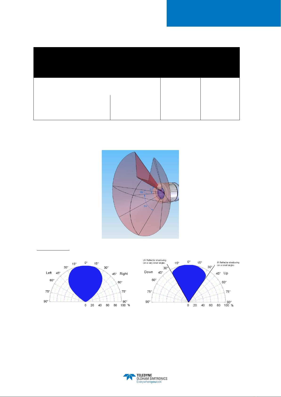
3.2 Field of View (Cone of Vision)
DF-TV7-XVA0
DF-TV7-XTA0
and
DF-TV7-XTB0
α
max : Maximum angle as defined in standard EN 54-
10 (2006) - § 5.4 30° 35°
Angle at 50% sensitivity
(in accordance with FM 3260
standard)
Horizontal total
97° 104°
Vertical Up / Down
20° / 35° 30° / 52°
The vertical viewing angle is limited by the self-test reflectors on a thin solid angle
DF-TV7-XVA0

MULTIFLAME DF-TV7
OPTICAL FLAME DETECTOR
OPERATING MANUAL
NOSP17662
Revision 03
13
DF-TV7-XTA0 and DF-TV7-XTB0
Typical horizontal detection: Typical vertical detection:
3.3 False alarm immunity (FM 3260)
Distance
m (ft.)
XTB0 (IR3)
Long range
XTA0 (IR3)
Standard
range
XVA0 (UVIR²)
Modulated /
Steady
75 % / 5 sec
(fact. setting)
100% / 5 sec
(fact. setting)
100 % / 2 sec
(fact. setting)
Arc welding,
steady, #7014,
3/16 in, 190A
3.6 / 3.6
(12/12)
No False
Alarm
No False
Alarm
No false Alarm
7.6 / 7.6
(25/25)
1.5 kW heater
3.0 / 1.8
(10/6)
No False
Alarm
No False
Alarm
No False
Alarm
100 W
incandescent lamp
0.9 / 0.9
(3/3)
No False
Alarm
No False
Alarm
No False
Alarm
Two 40 W
fluorescent lamps
0.9 / 0.9
(3/3)
No False
Alarm
No False
Alarm
No False
Alarm
100 W halogen
lamp
2.4 / 2.4
(8/8)
No False
Alarm
No False
Alarm
No False
Alarm

MULTIFLAME DF-TV7
OPTICAL FLAME DETECTOR
OPERATING MANUAL
14
NOSP17662
Revision 03
This manual suits for next models
5
Table of contents
Other TELEDYNE OLDHAM SIMTRONICS Security Sensor manuals


Popular Security Sensor manuals by other brands

SICK
SICK LD-MRS operating instructions

Videofied
Videofied IMD 200 Product installation sheet

tibelec
tibelec ST-15 manual

Pepperl+Fuchs
Pepperl+Fuchs SLCT Series Original instructions

Agilent Technologies
Agilent Technologies InfinityLab 1290 Infinity II user manual

B.E.G.
B.E.G. LUXOMAT PD4-M-3C-TRIO Series Installation and operating instruction


