Teledyne RD Instruments WorkHorse Rio Grande ADCP User manual
WorkHorse
Rio Grande ADCP
User’s Guide
P/N 957-6167-00 (January 2001)
RD Instruments
Acoustic Doppler Solutions


Table of Contents
1Introduction....................................................................................................................................... 1
2WorkHorse Rio Grande ADCP Applications .................................................................................. 2
3System Overview .............................................................................................................................. 2
3.1 Rio Grande ADCP Overview...............................................................................................................3
3.2 I/O Cable Overview.............................................................................................................................5
3.3 Optional Flash Memory Card ..............................................................................................................6
3.4 Spare Parts.........................................................................................................................................7
4WorkHorse Care................................................................................................................................ 8
4.1 General Handling Guidelines ..............................................................................................................8
4.2 Assembly Guidelines ..........................................................................................................................8
4.3 Deployment Guidelines.......................................................................................................................9
5Setup the WorkHorse Rio Grande ADCP ..................................................................................... 10
5.1 Serial Communication.......................................................................................................................10
5.2 What if the WorkHorse Does Not Respond.......................................................................................10
6Software........................................................................................................................................... 11
6.1 System Requirements.......................................................................................................................11
6.2 Software Installation..........................................................................................................................11
6.3 Utility Software ..................................................................................................................................12
7Power ............................................................................................................................................... 13
7.1 Bench-Top Battery Power Requirements..........................................................................................13
7.2 Operation Modes ..............................................................................................................................13
8Testing Your WorkHorse................................................................................................................ 14
9Compass Calibration...................................................................................................................... 15
9.1 Preparing for Calibration ...................................................................................................................15
9.2 Compass Calibration Verification......................................................................................................15
9.3 Compass Calibration Procedure .......................................................................................................16
10 Internal Pressure Sensor ............................................................................................................... 18
10.1 Pressure Sensor Maintenance..........................................................................................................18
11 Deployment Guide .......................................................................................................................... 19
11.1 Deployment Checklist .......................................................................................................................19
11.2 Prepare the ADCP for Deployment ...................................................................................................20
11.3 Deployment Software........................................................................................................................20
11.4 Deploy the ADCP..............................................................................................................................21
11.5 Send the Deployment Commands ....................................................................................................22
12 Reviewing the Data......................................................................................................................... 22
12.1 'Where' was the Data? ......................................................................................................................22
12.2 'When' was the Data? .......................................................................................................................22
12.3 'What' is the Data? ............................................................................................................................22
13 A Few Principles of Operation ...................................................................................................... 23
14 Technical Support .......................................................................................................................... 24

List of Figures
Figure 1. Rio Grande ADCP Overview ........................................................................................... 4
Figure 2. Connecting and Disconnecting the I/O Cable.................................................................. 5
Figure 3. I/O Cable Overview ......................................................................................................... 6
Figure 4. Memory Card Overview................................................................................................... 7
Figure 5. WorkHorse Rio Grande Connections ............................................................................ 10
Figure 6. Compass Alignment ...................................................................................................... 17
Figure 7. Visual Inspection before Deployment ............................................................................ 19
Figure 8. Prepare the ADCP ........................................................................................................ 20
Figure 9. Real-Time Deployment.................................................................................................. 21
List of Tables
Table 1: WorkHorse Rio Grande Application Guide ...................................................................... 2
Table 2: Spare Parts .....................................................................................................................7
Table 3: WorkHorse Software Main Modules .............................................................................. 11
Table 4: WorkHorse DOS Utility Software................................................................................... 12
Table 5: WorkHorse ADCP Tests ................................................................................................ 14
WorkHorse Rio Grande ADCP User's Guide
P/N 957-6167-00 (January 2001) page 1
Acoustic Doppler Solutions
WorkHorse Rio Grande ADCP User's Guide
1 Introduction
Thank you for purchasing the RD Instruments (RDI) Rio Grande Work-
Horse. This guide is designed to help first time WorkHorse users to set up,
test, and deploy their ADCP.
This guide is designed for use with the other WorkHorse Technical Manual
guides. Where needed, there are references to detailed information and fig-
ures contained in the WorkHorse Technical Manual.
WorkHorse Rio Grande deployments are most often Real-Time. Real-Time
use refers to the fact you are viewing the data as the ADCP collects it via a
personal computer. This data is also stored on the computer to allow for
data playback and processing at a later time.
NOTE. When you receive your WorkHorse, look for a set up card that
shows all of the pieces you should have in your box. If anything is missing
or damaged, contact RDI immediately.

WorkHorse Rio Grande ADCP User's Guide
page 2 RD Instruments
2 WorkHorse Rio Grande ADCP Applications
The Workhorse Rio Grande ADCP provides customers with reliable and
repeatable river discharge measurements, and displays the results through
its exceptional, user-friendly WinRiver software. For detailed information
on how to use WinRiver, see the WinRiver User’s Guide.
The WorkHorse Rio Grande ADCP can also be used in other moving vessel
real time applications that take advantage of the Rio Grande’s bottom track-
ing abilities. WinRiver is the most often used software package for Rio
Grande ADCP setup, real-time data collection, and data review. RDI also
offers the VmDas program for ADCP setup, real-time data collection, and
data review. For detailed information on how to use VmDas, see the VmDas
User’s Guide.
Table 1: WorkHorse Rio Grande Application Guide
Estuaries/River Costal and Continental Shelf
Rio Grande using WinRiver Rio Grande using VmDas
• River, stream and channel discharge • Plume tracking
• Suspended sediment load estimation • Environmental surveys
• Plume tracking • Planning new ports
• Bridge scouring • Current mapping
• Simultaneous bathymetry discharge, flow structure • Costal engineering
• Cable and pipe laying
• Circulation/model studies
3 System Overview
The WorkHorse Rio Grande is designed to measure real-time current pro-
files from temporary or permanent mounting in a vessel. The Rio Grande
ADCP system consists of an ADCP with Bottom Track mode, High Resolu-
tion Water Profiling modes, cables, and software. The input power re-
quirements for the Rio Grande are +12 VDC. The Rio Grande system re-
quires the addition of a Windows® compatible computer to collect data.
NOTE. Do not attempt to attach a Workhorse Monitor/Sentinel I/O cable or
power supply to the Workhorse Rio Grande ADCP. The Workhorse
Monitor and Sentinel ADCPs are 24 VDC systems. The Workhorse Rio
Grande uses 12 VDC only.
NOTE. The Rio Grande End-Cap is red to differentiate it from the Monitor
and Sentinel ADCPs. Do not swap end-caps between a Rio Grande and a
Monitor/Sentinel. The pin-outs are different on both the I/O cable
connector and the internal I/O cable.

WorkHorse Rio Grande ADCP User's Guide
P/N 957-6167-00 (January 2001) page 3
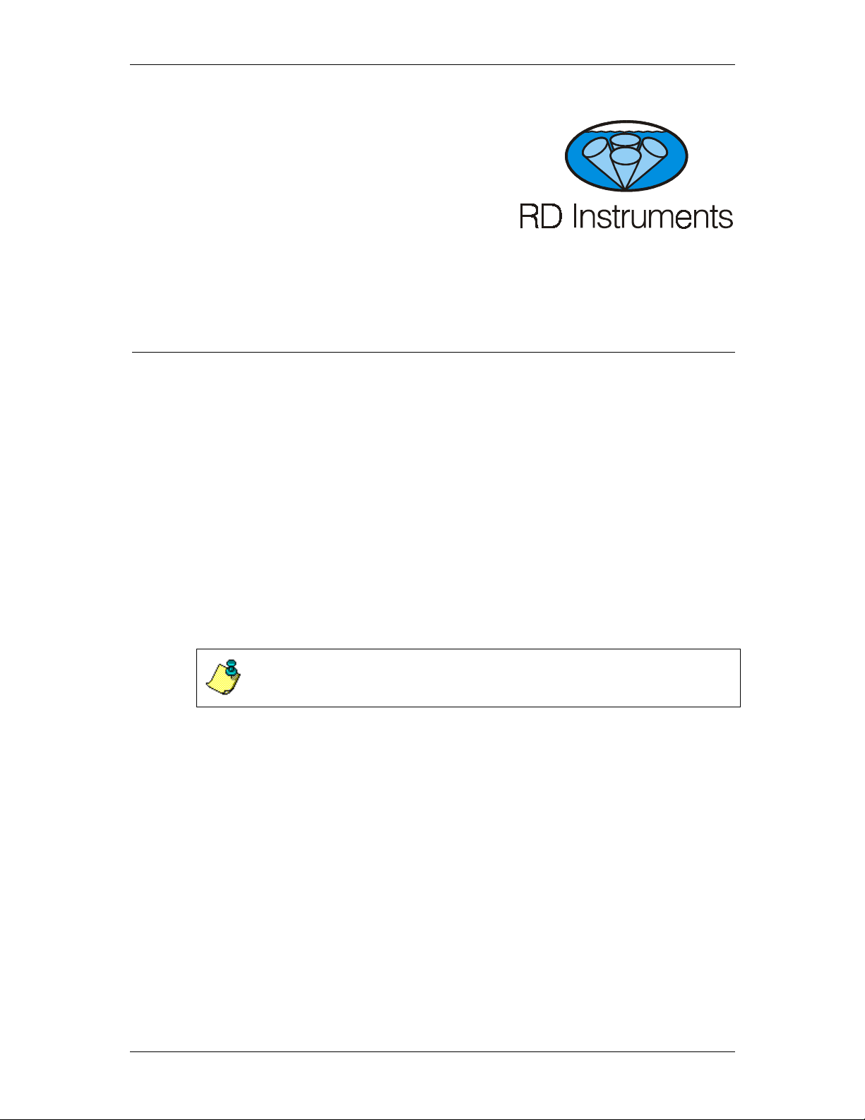
3.1 Rio Grande ADCP Overview
The transducer assembly contains the transducer ceramics and electronics.
Standard acoustic frequencies are 600, and 1200kHz. See the outline draw-
ings in the Installation Guide for dimensions and weights.
I/O Cable Connector – Input/Output (I/O) cable connects the WorkHorse
ADCP to the computer.
Beam-3 Mark – The Beam-3 mark shows the location of Beam-3 (Forward).
Urethane Face – The urethane face covers the transducer ceramics. Never
set the transducer on a hard surface. The urethane face may be damaged.
Housing – The standard WorkHorse housing allows deployment depths to
200 meters.
Thermistor – The Thermistor measures the water temperature.
Pressure Sensor – The Optional pressure sensor measures water pressure
(depth).
Transducer Head – The WorkHorse electronics and transducer ceramics are
mounted to the transducer head. The numbers embossed on the edge of the
transducer indicates the beam number. When assembling the unit, match
the transducer beam number with the Beam 3 mark on the end-cap.
End-Cap – The end-cap holds the I/O cable connector. When assembling
the unit, match the Beam 3 mark on the end-cap with beam 3 number on the
transducer.
WorkHorse Rio Grande ADCP User's Guide
page 4 RD Instruments
URETHANE FACE
BEAM 3 MARK
THERMISTOR
PRESSURE SENSOR
(OPTIONAL)
TRANSDUCER
HEAD
HOUSING
END-CAP
I/O CABLE
CONNECTOR
Figure 1. Rio Grande ADCP Overview

WorkHorse Rio Grande ADCP User's Guide
P/N 957-6167-00 (January 2001) page 5
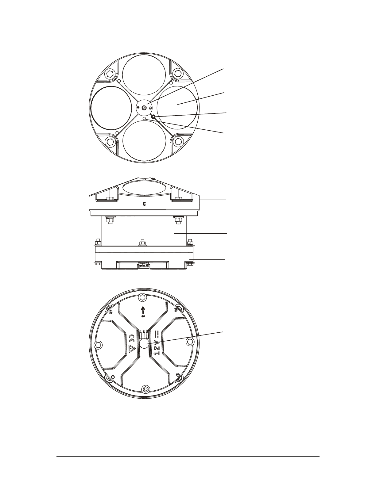
3.2 I/O Cable Overview
Always remove the retaining strap on the end-cap underwater-connect cable
and dummy plug when disconnecting them. Failure to do so will break
the retainer strap.
Do not apply any upward force on the end-cap connector as the I/O cable is
being disconnected. Stressing the end-cap connector may cause the
ADCP to flood. Read the Maintenance guide for details on disconnecting
the I/O cable.
Figure 2. Connecting and Disconnecting the I/O Cable
NOTE. The Rio Grande End-Cap is red to differentiate it from the Monitor
and Sentinel ADCPs. Do not swap end-caps between a Rio Grande and a
Monitor/Sentinel. The pin-outs are different on both the I/O cable
connector and the internal I/O cable.
WorkHorse Rio Grande ADCP User's Guide
page 6 RD Instruments
1234
567
8
1
2
5
6
3
7
4
8
3
2
9
8
5
4
P3 (RED)
P4 (BLACK)
P1 P2
BLK
WHT
BLU
BRN
GRN
RED
ORG
YEL
WHT
BLK
RS-232IN/CH A RS485A/RS-422 OUT A
RS-232OUT/CH A RS485B/RS-422 OUT B
CH B RS485B/RS-422 IN A
COMMUNICATION RETURN
SPARE
POWER (+)
POWER (-)
CH B RS485B/RS-422 IN B
RED
BLK
Figure 3. I/O Cable Overview
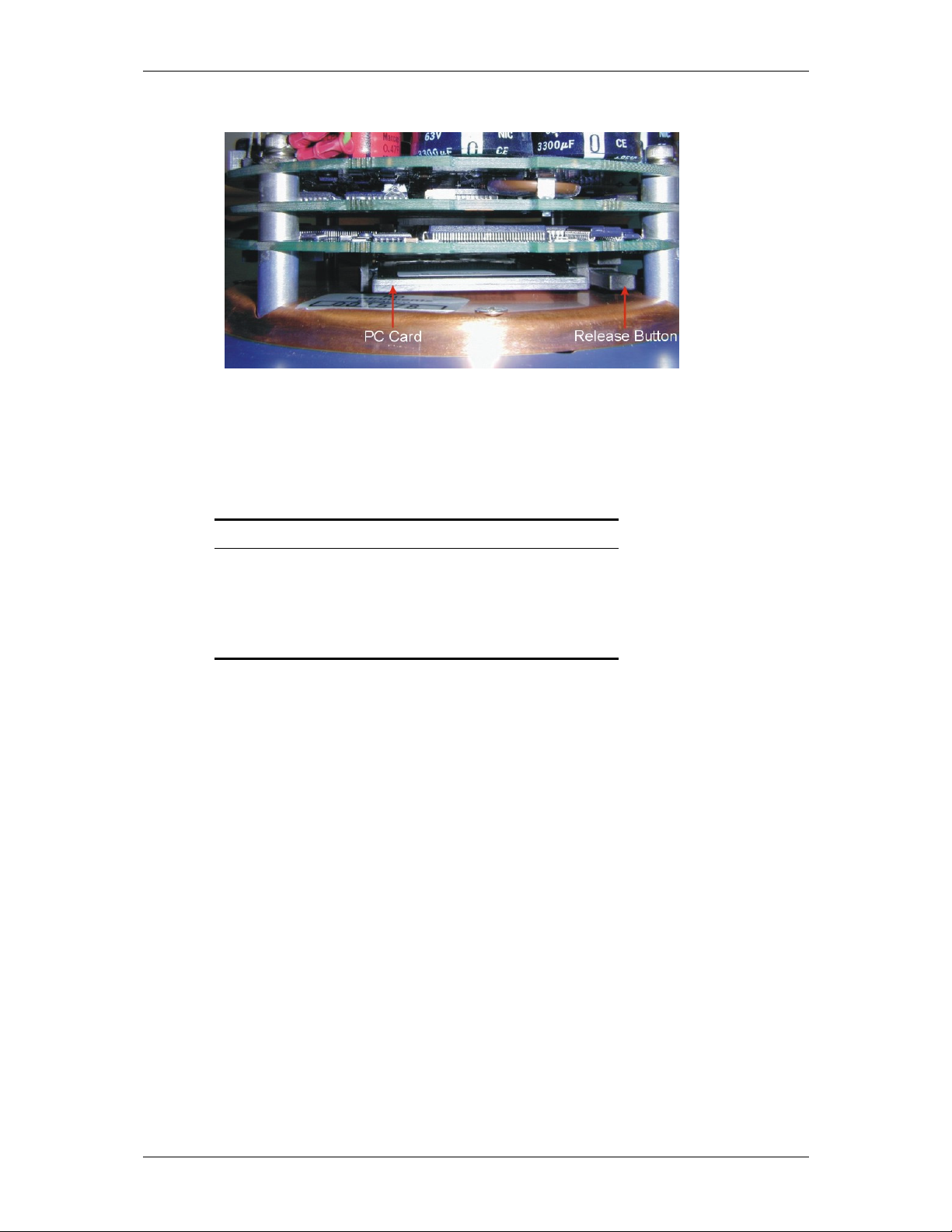
3.3 Optional Flash Memory Card
Flash memory cards (see Figure 4, page 7) are available in 16, 20, 40, 85
and 220-MB cards. The internal recorder holds two cards for a maximum
of 440 MB of recording space. The PC Card recorder is located on the
Digital Signal Processor (DSP) board inside the Workhorse’s electronics.
To recover data, the card can be removed and used in a personal computer
(PC), or left in the Workhorse, and accessed by using WinSC (see the WinSC
User's Guide).
NOTE. The WorkHorse Rio Grande does not come with flash memory, but
has the same capacity as a WorkHorse Sentinel.
NOTE. WinSC is not provided with WorkHorse Rio Grande systems, but is
available for free download at www.rdinstruments.com.
WorkHorse Rio Grande ADCP User's Guide
P/N 957-6167-00 (January 2001) page 7
Figure 4. Memory Card Overview
3.4 Spare Parts
The following parts are included in the spare parts kit.
Table 2: Spare Parts
Description Part number
O-ring, face 2-260
Desiccant, sealed bag DES3
Lubricant, silicone, 5.3 oz, Dow-Corning DC-111
Fuse, 3.0 Amp, 250V GMA-3A

WorkHorse Rio Grande ADCP User's Guide
page 8 RD Instruments
4 WorkHorse Care
This section contains a list of items you should be aware of every time you
handle, use, or deploy your WorkHorse. Please refer to this list often.
4.1 General Handling Guidelines
• Never set the transducer on a hard or rough surface. The
urethane faces may be damaged.
• Always remove the retaining strap on the end-cap underwa-
ter-connect cable and dummy plug when disconnecting them.
Failure to do so will break the retainer strap.
• Do not apply any upward force on the end-cap connector as
the I/O cable is being disconnected. Stressing the end-cap
connector may cause the ADCP to flood. Read the Main-
tenance guide for details on disconnecting the I/O cable.
• Do not expose the transducer faces to prolonged sunlight.
The urethane faces may develop cracks. Cover the trans-
ducer faces on the Workhorse if it will be exposed to sun-
light.
• Do not expose the I/O connector to prolonged sunlight. The
plastic may become brittle. Cover the connector on the
Workhorse if it will be exposed to sunlight.
• Do not store the ADCP in temperatures over 75 degrees C.
The urethane faces may be damaged. Check the tempera-
ture indicator inside the shipping case. It changes color if the
temperature limit is exceeded.
• Do not scratch or damage the O-ring surfaces or grooves. If
scratches or damage exists, they may provide a leakage
path and cause the ADCP to flood. Do not risk a deploy-
ment with damaged O-ring surfaces.
• Do not lift or support a WorkHorse by the external I/O cable.
The connector or cable will break.
4.2 Assembly Guidelines
• Read the Maintenance guide for details on WorkHorse re-
assembly. Make sure the housing assembly O-rings stay in
their groove when you re-assemble the WorkHorse. Tighten
the hardware as specified. Loose, missing, stripped hard-
ware, or damaged O-rings can cause the WorkHorse
transducer to flood.

WorkHorse Rio Grande ADCP User's Guide
P/N 957-6167-00 (January 2001) page 9
• Place a light amount of DC-111 lubricant on the end-cap
connector pins (rubber portion only). This will make it eas-
ier to connect or remove the I/O cable and dummy plug.
• Do not connect or disconnect the I/O cable with power ap-
plied. An exception to this is the external battery case. The
external battery case connector is always “hot” when batter-
ies are installed. When you connect the cable with power
applied, you may see a small spark. The connector pins
may become pitted and worn.
• The WorkHorse I/O cable is wet mate-able, not under water
mate-able.
4.3 Deployment Guidelines
• Align the compass whenever the battery pack or recorder
module is replaced, or when any ferrous metals are relocated
inside or around the WorkHorse housing. Ferro-magnetic
materials affect the compass.
• The AC power adapter is not designed to withstand water.
Use caution when using on decks in wet conditions.
• Avoid using ferro-magnetic materials in the mounting
fixtures or near the Workhorse. Ferro-magnetic materials
affect the compass.

WorkHorse Rio Grande ADCP User's Guide
page 10 RD Instruments
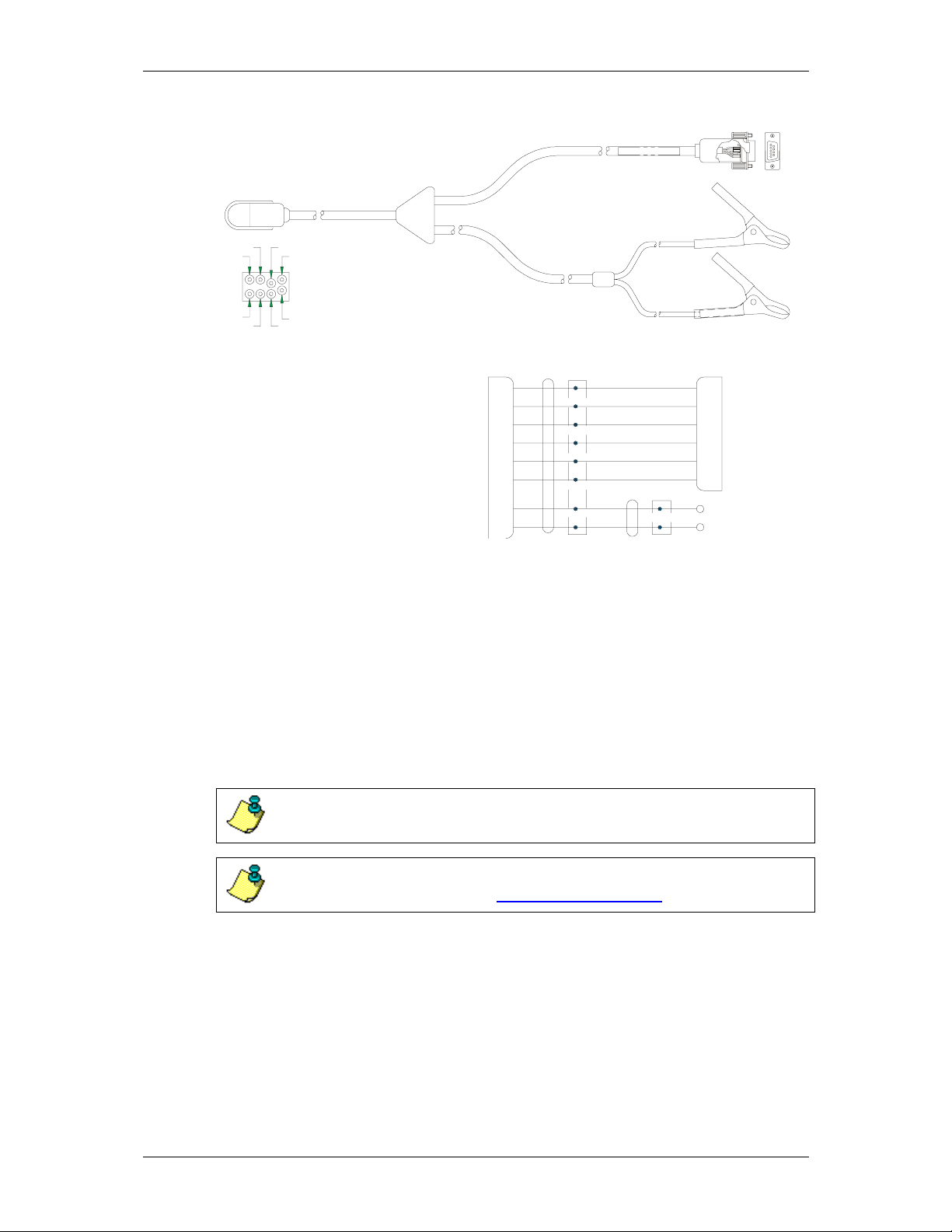
5 Setup the WorkHorse Rio Grande ADCP
Figure 5 illustrates how to connect the WorkHorse cables and adapters on
your workbench. The internal battery plugs into a connector on the top
circuit board.
You will need a container of water large enough to submerge the Work-
Horse’s transducer head into during testing (two to three inches of water is
sufficient). Testing the WorkHorse out of water may cause some tests to
fail but causes no harm to the WorkHorse.
I/O CABLE
12 VD
C
BATTERY
COMPUTER
ADCP
Figure 5. WorkHorse Rio Grande Connections
5.1 Serial Communication
The standard communications settings for a WorkHorse Rio Grande is RS-
232, 9600-baud, no parity, 8 data bits and 1 stop bit. If the serial protocol is
set for RS232 and your computer expects RS422, you will need an RS232
to RS422 adapter between the WorkHorse cable and your computer. You
can set the WorkHorse for baud rates other than 9600 baud.
RS422. The WorkHorse Rio Grande is normally set for RS232, but it can be
changed to RS422 by changing a switch setting. The switch is in plain view
on the top circuit board, near the cable connectors. Its settings are plainly
marked on the board. This user’s guide assumes that you use RS232.
5.2 What if the WorkHorse Does Not Respond
If your WorkHorse does not respond, check the serial port, cables, and
power. If necessary, refer to the Troubleshooting Guide in the WorkHorse
technical manual.

WorkHorse Rio Grande ADCP User's Guide
P/N 957-6167-00 (January 2001) page 11
6 Software
RDI has utility programs to help you set up, use, test, and trouble-shoot
your WorkHorse ADCP. Each program has a help file that you can print, or
you can view help while running the program.
Table 3: WorkHorse Software Main Modules
Program Name Description
DumbTerm Windows ADCP communication program. Use this program to
"talk" to the ADCP and to run test script files. DumbTerm is
included on the RDI Tools CD. For detailed information on
how to use DumbTerm, see the RDI Tools User's Guide.
WinADCP Gives users a visual display of the entire set of data. You can
zoom in on a portion of the data for closer analysis and you
can export data to text or MatLab files. For detailed informa-
tion on how to use WinADCP, see the WinADCP User's Guide.
Documentation
CD
The Documentation CD has an Adobe Acrobat® (*.pdf) elec-
tronic version of the WorkHorse Technical Manual. Use the
Documentation CD to search for information. For detailed in-
formation on how to use Adobe Acrobat® and the Documenta-
tion CD, see the Read This First guide.
6.1 System Requirements
The WorkHorse software requires the following:
• Windows 95®, Windows 98®, or Windows® NT 4.0 with
Service Pack 4 installed
• Pentium class PC 233 MHz (350 MHz or higher recom-
mended)
• 32 megabytes of RAM (64 MB RAM recommended)
• 6 MB Free Disk Space (20 MB recommended)
• One Serial Port (two High Speed UART Serial Ports recom-
mended)
• Minimum display resolution of 800 x 600, 256 color (1024 x
768 recommended)
6.2 Software Installation
To install the WorkHorse software, do the following.
a. Insert the compact disc into your CD-ROM drive and then follow the
browser instructions on your screen. If the browser does not appear,
complete Steps “b” through “d.”

WorkHorse Rio Grande ADCP User's Guide
page 12 RD Instruments
b. Click the Start button, and then click Run.
c. Type <drive>:launch. For example, if your CD-ROM drive is drive D,
type d:launch.
d. Follow the browser instructions on your screen
6.3 Utility Software
The following DOS programs (on the RDI Tools CD) have been provided to
supplement features not yet implemented into the Windows environment.
RDI will incorporate these features in future releases. These programs will
be installed to the directory C:\Program Files\Rd Instruments\Utilities when
you run the RDI Tools installation program.
Table 4: WorkHorse DOS Utility Software
Program Name Description
BBLIST Executable program that can be operated through the Windows environment.
This program will display binary data in tabular format as well as convert the
data into an ASCII file.
BBBATCH Automatically converts a named binary data set to a named ASCII data set
using an existing format file. Use this program to convert binary files unat-
tended through a DOS batch file.
BBCONV Executable program that cannot be operated through the Windows environ-
ment. Removes user selected data from binary files and stores the information
into ASCII comma delimited format. See BCONV.DOC for decoder file format.
BBMERGE Executable program that cannot be operated through the Windows environ-
ment. BBMERGE merges ASCII comma delimited format data described by a
decoder (.DEC) file into the raw BroadBand ADCP data file "infilename", result-
ing in an output ADCP data file called "outfilename". See BCONV.DOC for
decoder file format.
BBSUB Executable program that cannot be operated through the Windows environ-
ment. BBSUB starts copying ensembles from 'infilename' to 'outfilename' start-
ing with the user specified “Start” and “End” ensemble number. This is intended
to allow users to subsection binary data files.
SS Executable program that can be operated through the Windows environment.
SS allows you to quickly calculate the speed of sound in the water.
SURFACE Executable program that cannot be operated through the Windows environ-
ment. Surface estimates the range from the ADCP to the water surface or bot-
tom from the echo intensity data. This program does not change the original
data. It creates a text file with the estimated ranges. Intended for customers to
estimate where to cut off their data.
CHECKDAT Executable program that cannot be operated through the Windows environ-
ment. CHECKAT will scan a data file for missing ensembles, ensemble number
out of order, bad checksum ensembles and ensembles with bit errors. If the
DOS redirect command (> symbol) is used then the output will be placed into a
file.
C++ Code Library The C++ Code library has been provided to help you in the creation of your own
programs. These files are provided as is and in general are not supported. Use
at your own discretion. The files are located in the directory: C:\Program
Files\Rd Instruments\Utilities\C_Code.

WorkHorse Rio Grande ADCP User's Guide
P/N 957-6167-00 (January 2001) page 13
7 Power
The Rio Grande requires a DC supply between 10.5 volts and 18 volts. Ei-
ther an external DC power supply or battery can provide this power. If you
are using a battery, use the largest rated amp-hour battery as possible. A car
battery should last one to two days powering a 600-kHz ADCP.
NOTE. Check that the battery voltage is above 10 Volts DC. Rio Grande
ADCPs will work at 10 volts; however, batteries with voltages below 11
volts are at or near their end of life and are approaching uselessness.
7.1 Bench-Top Battery Power Requirements
While the WorkHorse is awake and responding to commands, it consumes
approximately 2.2 watts. A single internal battery pack supplies this power
level for about five days. When the WorkHorse is asleep, it consumes less
than one mw. A standard battery pack supplies sleep power for years. At
every opportunity, the WorkHorse will “sleep” to conserve power while de-
ployed.
7.2 Operation Modes
The WorkHorse has two modes of operation: command mode, and ping
mode (also referred to as “Deployment Saver” Mode). Depending on what
mode the ADCP is in; it will go either to sleep or to resume pinging.
In the Command Mode
Whenever you wake up your WorkHorse, power dissipation increases from
less than one mw to around 2.2 w. If you leave the WorkHorse in command
mode without sending a command for more than five minutes, the Work-
Horse automatically goes to sleep. This protects you from inadvertently
depleting batteries.
In the Ping Mode
After you send commands to the WorkHorse that tells it to start collecting
data, the WorkHorse goes into deployment saver mode. If power is some-
how removed and later restored, the WorkHorse simply picks up where it
left off and continues to collect data using the same setup.

WorkHorse Rio Grande ADCP User's Guide
page 14 RD Instruments
8 Testing Your WorkHorse
Use the following steps to test the ADCP.
a. Interconnect and apply power to the system as described in “Setup the
WorkHorse Rio Grande ADCP,” page 10.
b. Start the DumbTerm program (for help on using DumbTerm, see the RDI
Tools User's Guide).
c. Press
<F2> and run the script file TestWH.txt. The TestWH.txt script file
runs PS0, PS3, PA, PC2, and the PC1 tests. The results of the tests will
be printed to the screen and saved to the log file WH_RSLTS.txt. The
WH_RSLTS.txt file will be created in the same directory that Dumb-
Term is running from.
Table 5 lists the tests DumbTerm runs, gives you guidelines for running the
tests, and tells you what the results mean.
Table 5: WorkHorse ADCP Tests
Test Guidelines Results
PS0 Displays system parameters. Verify the information is
consistent with what you
know about the setup of
your system.
PA Extensive pre-deployment test that tests
the signal path and all major signal proc-
essing subsystems. This test may not
pass unless the WorkHorse transducer
face is immersed water.
All tests must pass.
PC2 Continuously updates sensor display.
Rotate and tilt WorkHorse and watch the
readings on the display change.
Satisfy yourself that the
readings make sense.
PC1 Beam continuity test. Follow instructions
to rub each beam in turn to generate a
noise signal the WorkHorse uses to verify
the transducer beam is connected and
operational.
All beams must pass.

WorkHorse Rio Grande ADCP User's Guide
P/N 957-6167-00 (January 2001) page 15
9 Compass Calibration
The main reason for compass calibration is battery replacement. Each new
battery carries a different magnetic signature. The compass calibration al-
gorithm corrects for the distortions caused by the battery to give you an ac-
curate measurement. You should be aware of the following items:
• We recommend against calibrating the WorkHorse while on a
ship. The ship’s motion and magnetic fields from the hull
and engine will likely prevent successful calibration.
• If you think your mounting fixture or frame has some mag-
netic field or magnetic permeability, calibrate the WorkHorse
inside the fixture. Depending on the strength and complexity
of the fixture’s field, the calibration procedure may be able to
correct it.
NOTE. If you will deploy your WorkHorse looking up, calibrate it looking
up. If you will deploy it looking down, calibrate it looking down.
9.1 Preparing for Calibration
a. Place the WorkHorse on a piece of strong cardboard on top of a smooth
wooden (non-magnetic) table. If a wooden table is not available, place
the WorkHorse on the floor as far away from metal objects as possible.
Use the cardboard to rotate the WorkHorse during calibration—this way
you will not scratch the WorkHorse.
b. Connect the WorkHorse as shown in Figure 5, page 10.
c. Start DumbTerm. See the RDI Tools User's Guide for assistance on
using DumbTerm.
9.2 Compass Calibration Verification
Compass calibration verification is an automated built-in test that measures
how well the compass is calibrated. The procedure measures compass pa-
rameters at every 5º of rotation for a full 360º rotation. When it has col-
lected data for all required directions, the WorkHorse computes and dis-
plays the results.
NOTE. Verify the compass if you have just replaced the battery (Sentinel
only), memory module (optional for Rio Grande ADCPs), or any ferrous
metals is relocated inside or around the WorkHorse housing.
Start the test with the AX-command and follow the instructions. Place the
ADCP in the same orientation as it will be deployed. The WorkHorse
can be vertical (it can rest on its end cap), or it can be tilted (it could rest on

WorkHorse Rio Grande ADCP User's Guide
page 16 RD Instruments
a transducer face). Whatever its tilt, the tilt must remain constant as you
rotate the WorkHorse. When prompted, rotate the WorkHorse smoothly and
slowly. Pay particular attention to the Overall Error. For example;
HEADING ERROR ESTIMATE FOR THE CURRENT COMPASS CALIBRATION:
OVERALL ERROR:
Peak Double + Single Cycle Error (should be < 5(): ( 1.55(
DETAILED ERROR SUMMARY:
Single Cycle Error: ( 1.54(
Double Cycle Error: ( 0.07(
Largest Double plus Single Cycle Error: ( 1.61(
RMS of 3rd Order and Higher + Random Error: ( 0.31(
If the overall error is less than 5°, the compass does not require alignment.
You can align the compass to reduce the overall error even more (if
desired).
9.3 Compass Calibration Procedure
The built-in automated compass calibration procedure is similar to the
alignment verification, but requires three rotations instead of one. The
WorkHorse uses the first two rotations to compute a new calibration matrix
and the third to verify the calibration. It will not accept the new matrix
unless the calibration was carried out properly, and it asks you to verify that
you want to use the new calibration if it is not as good as the previous cali-
bration. While you are turning the WorkHorse for the two calibration rota-
tions, the WorkHorse checks the quality of the previous calibration and dis-
plays the results. It compares these results with the results of the third cali-
bration rotation.
There are two compass calibrations to choose from; one only corrects for
hard iron while the other corrects for both hard and soft iron characteristics
for materials rotating with the ADCP. Hard iron effects are related to resid-
ual magnetic fields and cause single cycle errors while soft iron effects are
related to magnetic permeability that distorts the earth’s magnetic field and
causes double cycle errors. In general, the hard iron calibration is recom-
mended because the effect of hard iron dominates soft iron. If a large dou-
ble cycle error exists, then use the combined hard and soft iron calibration.
a. Start DumbTerm.
b. Start the test with the AF-command and choose the calibration type.
c. Place the ADCP in the same orientation as it will be deployed.
d. When prompted, rotate the WorkHorse slowly 360 degrees.
e. The second rotation requires the WorkHorse to be tilted on an adjacent
beam. Follow the on-screen instructions to orient the unit correctly. Tilt
an upward-looking WorkHorse with a block under one side of the end
cap. A 35-mm block gives you an 11º tilt. When prompted, rotate the
WorkHorse slowly 360 degrees.
Table of contents
Popular Transducer manuals by other brands

Simrad
Simrad 18-11 - REV C datasheet

Automationdirect.com
Automationdirect.com AcuAmp 3ACT Series installation instructions

Simrad
Simrad 200-28E - REV B datasheet

Humminbird
Humminbird transducer Assembly & operating instructions

turck
turck HART IM33-11-Hi/24VDC Series quick start guide

KYOWA
KYOWA BER-A-15S instruction manual

Lowrance
Lowrance Simrad LiveSight Ice installation guide

Ashcroft
Ashcroft k1 instruction sheet

Schertler
Schertler DYN-V user manual

Camille Bauer
Camille Bauer Sineax p 530 operation instruction

Measurement Computing
Measurement Computing KPSI 351 Series user manual

CARLO GAVAZZI
CARLO GAVAZZI SPT-90 operating instructions


