Teledyne PowerMAX User manual

Outdoor PowerMAX Systems
High Power Outdoor SSPA Modules
C-Band System Installation Manual
215861 REV C ECO A25602 01/2021
Teledyne Paradise Datacom (814) 238-3450
11361 Sunrise Park Drive [email protected]
Rancho Cordova, CA 95742 USA www.paradisedata.com

2 215861 REV C Installation, Outdoor HPO PowerMAX System
Teledyne Paradise Datacom, a division of Teledyne Defense Electronics LLC, is a single source for high
power solid state amplifiers (SSPAs), Low Noise Amplifiers (LNAs), Block Up Converters (BUCs), and
Modem products. Operating out of two primary locations, Rancho Cordova, CA, USA, and Witham, Unit-
ed Kingdom, Teledyne Paradise Datacom has more than a 20 year history of providing innovative solu-
tions to enable satellite uplinks, battlefield communications, and cellular backhaul.
Teledyne Paradise Datacom Teledyne Paradise Datacom Ltd.
11361 Sunrise Park Drive 2&3 The Matchyns, London Road, Rivenhall End
Rancho Cordova, CA 95742 USA Witham, Essex CM8 3HA England
(814) 238-3450 +44 (0) 1376 515636
+44 (0) 1376 533764 (fax)
Information in this document is subject to change without notice. The latest revision of this document
may be downloaded from the company web site: http://www.paradisedata.com.
Use and Disclosure of Data
This product is classified as EAR99 and is subject to U.S. Department of Commerce regulations. Export,
reexport or diversion contrary to U.S. law is prohibited.
Proprietary and Confidential
The information contained in this document is the sole property of Teledyne Paradise Datacom. Any re-
production in part or as a whole without the written permission of Teledyne Paradise Datacom is prohib-
ited.
All other company names and product names in this document are property of the respective compa-
nies.
© 2017-2021 Teledyne Paradise Datacom
Printed in the USA

Installation, Outdoor HPO PowerMAX System 215861 REV C 3
Table of Contents
Section 1: Introduction ............................................................................................... 7
1.0 Introduction ................................................................................................... 7
1.1 Inspection and Unpacking ............................................................................7
1.2 Installation Conventions................................................................................7
Section 2: Installation, 8-Way System ....................................................................... 9
2.0 Introduction ................................................................................................... 9
2.1 Installation..................................................................................................... 9
2.1.1 Prepare Location Decking............................................................. 11
2.1.2 Install System Framework............................................................. 13
2.1.2.1 Install Uni-Strut Support (63 Inch) ................................... 13
2.1.2.2 Install Uni-Strut Supports (18 Inch) ................................. 14
2.1.3 Install Waveguide/Combiner Arrays .............................................. 14
2.1.4 Install High Power Outdoor SSPA Modules .................................. 16
2.1.5 Install Magic Tee/Termination ....................................................... 17
2.1.5.1 Install Magic Tee Termination Supports .......................... 18
2.1.5.2 Install Magic Tee Termination ......................................... 18
2.1.5.3 Connect Flexible Waveguide .......................................... 19
2.1.6 Install Optional Maintenance Switch ............................................. 20
2.1.6.1 Install Optional Maintenance Switch Controller ............... 20
2.1.6.2 Install Optional Maintenance Switch ............................... 20
2.1.6.3 Install Optional Maintenance Termination Supports ........ 21
2.1.6.4 Install Optional Maintenance Termination ....................... 21
2.1.6.5 Install Optional Maintenance Waveguide ........................ 22
2.1.7 Install Optional AC Distribution Box .............................................. 23
2.1.8 Install RF Distribution Box............................................................. 24
2.1.9 Install Outdoor Controllers ............................................................ 25
2.1.10 Connect Cables........................................................................... 26
2.1.10.1 Forward Sample In ........................................................ 26
2.1.10.2 Reflected Sample In ...................................................... 26
2.1.10.3 RF Distribution Cables .................................................. 26
2.1.10.4 Auxiliary Power Cable (L213830-7 or L213830-1)......... 27
2.1.10.5 SSPA Module M&C Cables (L213827-1, -2) ................. 28
2.1.10.6 Outdoor Controller DC Input Cables (L213826-1, -2) .... 29
2.1.10.7 System Link Cable (L213828-1) .................................... 30
2.1.10.8 Optional Ethernet Cables .............................................. 30
2.1.10.9 Optional Mute Switch Cable ......................................... 31
2.3 Weatherize Cable Connections .................................................................. 32
Section 3: Installation, 16-Way System ................................................................... 33
3.0 Introduction ................................................................................................. 33
3.1 Installation................................................................................................... 33
3.1.1 Prepare Location Decking............................................................. 35
3.1.2 Install System Framework............................................................. 37
3.1.2.1 Install Optional Maintenance Termination Supports ........ 37
3.1.2.2 Install Optional Maintenance Termination ....................... 37
3.1.2.3 Install Output Magic Tee Termination Supports .............. 38

4 215861 REV C Installation, Outdoor HPO PowerMAX System
3.1.2.4 Install Output Magic Tee Termination.............................. 38
3.1.2.5 Install Uni-Strut Supports (99 Inch) ................................. 39
3.1.2.6 Install System Termination Lower Uni-Strut (45 Inch) ..... 40
3.1.2.7 Install System RF Distribution Upper Uni-Strut (45 Inch) 41
3.1.2.8 Install System Termination Upper Uni-Strut (45 Inch) ..... 42
3.1.2.9 Install System Termination Support Uni-Strut ................ 43
3.1.3 Install Waveguide/Combiner Arrays.............................................. 44
3.1.4 Install High Power Outdoor SSPA Modules .................................. 44
3.1.5 Install 8-Way Output Magic Tees and Terminations ..................... 44
3.1.6 Install System Termination............................................................ 45
3.1.7 Install 16-Way Magic Tee Assembly ............................................. 46
3.1.8 Install 8-Way RF Output Waveguide............................................. 47
3.1.9 Install System RF Distribution Box Assembly ............................... 48
3.1.9.1 Optional Ethernet Switch................................................. 48
3.1.10 Install Optional AC Distribution Boxes ........................................ 49
3.1.11 Install RF Distribution Boxes ....................................................... 49
3.1.12 Install Outdoor Controllers .......................................................... 49
3.1.13 Connect Cables .......................................................................... 50
3.1.13.1 Forward Sample In ........................................................ 50
3.1.13.2 RF Distribution Cables .................................................. 50
3.1.13.3 Forward/Reflected Power Sample Cables..................... 50
3.1.13.4 Auxiliary Power Cable (L213830-8 or L213830-9) ........ 51
3.1.13.5 SSPA Module M&C Cables (L213827-1, -2) ................. 52
3.1.13.6 Mute Signal Jumper Cable (L215836-1)........................ 52
3.1.13.7 Outdoor Controller DC Input Cables (L213826-1, -2).... 53
3.1.13.8 System Link Cable (L213828-4).................................... 54
3.1.13.9 Optional Ethernet Cables .............................................. 54
3.2 Install Optional Maintenance Switch........................................................... 55
3.2.1 Install Optional Maintenance Switch Controller............................. 55
3.2.2 Install Optional Maintenance Switch ............................................ 55
3.2.3 Install Optional Maintenance Termination Supports...................... 56
3.2.4 Install Optional Maintenance Termination..................................... 57
3.2.5 Install Optional Maintenance Waveguide...................................... 58
3.2.6 Optional Mute Switch Cable (L215628-3) ..................................... 59
3.3 Weatherize Cable Connections .................................................................. 60
Appendix A ................................................................................................................ 61

Installation, Outdoor HPO PowerMAX System 215861 REV C 5
Figures
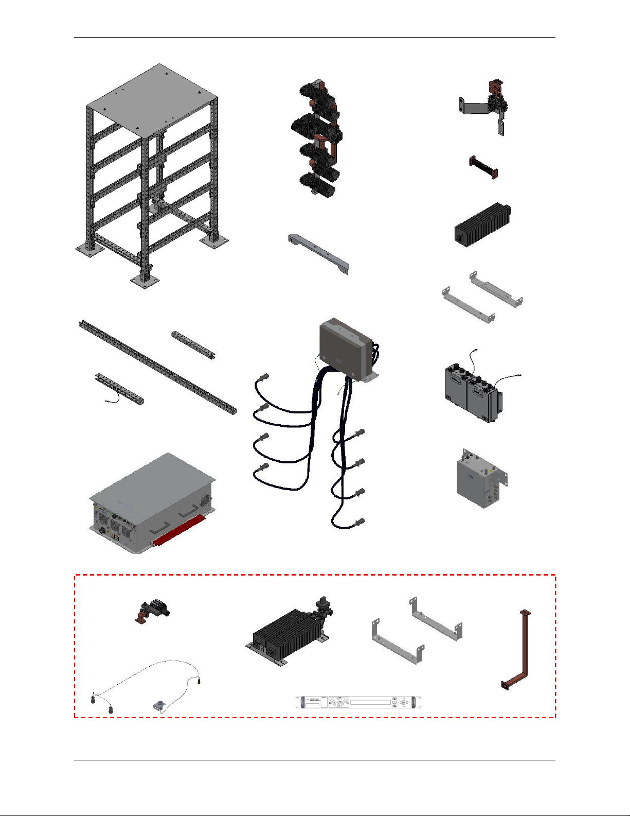
Figure 2-1: System Components, 8-Way System with Maintenance Switch ...... 8
Figure 2-2: Installation, Base Mounting and Anchor Points, 8-way System........ 9
Figure 2-3: System Outline, Top View ............................................................. 10
Figure 2-4: System Outline, System RF Output End View .............................. 10
Figure 2-5: Install Uni-Strut Support (63 Inch Segment)................................... 11
Figure 2-6: Install Uni-Strut Support (18 Inch Segments) ................................. 12
Figure 2-7: Install Waveguide/Combiner Array Mounting Bracket (Top)........... 12
Figure 2-8: Install Waveguide/Combiner Array Mounting Bracket (Bottom) ..... 13
Figure 2-9: Mount Waveguide/Combiner Arrays to Uni-Strut .......................... 13
Figure 2-10: Install High Power Outdoor SSPA Modules ................................ 14
Figure 2-11: Install Magic Tee Assembly ......................................................... 15
Figure 2-12: Install Termination Supports......................................................... 16
Figure 2-13: Attach Termination to Support...................................................... 16
Figure 2-14: Connect Termination W/G Flange to Magic Tee ......................... 17
Figure 2-15: Install Flex Waveguide ................................................................. 17
Figure 2-16: Install Optional Maintenance Switch ........................................... 18
Figure 2-17: Connect Maintenance Termination Supports ............................... 19
Figure 2-18: Install Maintenance Termination ................................................. 19
Figure 2-19: Connect Maintenance Waveguide to Switch ................................ 20
Figure 2-20: Connect Maintenance Waveguide to Termination........................ 20
Figure 2-21: Install Optional AC Distribution Box ............................................. 21
Figure 2-22: Install RF Distribution Box ............................................................ 22
Figure 2-23: Install Outdoor Controllers............................................................ 23
Figure 2-24: System Auxiliary Power Cable, L213830-1 or L213830-7............ 25
Figure 2-25: SSPA Module M&C Cable, L213827-1/-2 ................................... 26
Figure 2-26: Outdoor SSPA Controller DC Input Cable, L213826-1/-2............. 27
Figure 2-27: System Link Cable, L213828-1.................................................... 28
Figure 2-28: Optional Ethernet Cables, L213824-6/-7...................................... 28
Figure 2-29: Mute Switch Cable ....................................................................... 29
Figure 2-30: Install Cable Bracket to Uni-strut Frame....................................... 29
Figure 2-31: Maintenance Switch Controller Cable ......................................... 30
Figure 3-1: System Components, 16-Way System .......................................... 34
Figure 3-2: Installation, Base Mounting and Anchor Points, 16-way System.... 35
Figure 3-3: Installation, 16-way System, Top View........................................... 36
Figure 3-4: Installation, Magic Tee Termination Supports ................................ 38
Figure 3-5: Attach Termination to Support........................................................ 38
Figure 3-6: Connect 99-inch Uni-Strut Between 8-Way Systems ..................... 39
Figure 3-7: Mounting Hardware, 99-inch Uni-Strut Segments .......................... 39
Figure 3-8: Installation, System Termination, Lower Uni-Strut Support............ 40
Figure 3-9: Installation, Magic Tee Termination Lower Support Bracket .......... 40
Figure 3-10: Installation, System Controller Upper Uni-Strut Support .............. 41
Figure 3-11: Installation, System Termination Upper Support Uni-Strut (x2).... 42
Figure 3-12: Installation, System Termination Support Uni-Strut Assemblies .. 43
Figure 3-13: Installation, System Termination, Upper View.............................. 45
Figure 3-14: Installation, System Termination, Lower View.............................. 45
Figure 3-15: Installation, 16-Way Magic Tee Assembly.................................... 46
Figure 3-16: Installation, 8-Way RF Output Waveguide ................................... 47
Figure 3-17: Installation, System Signal Box Assembly.................................... 48
Figure 3-18: Auxiliary Power Cable, L213830-8 or L213830-9......................... 51
Figure 3-19: SSPA Module M&C Cable, L213827-1/-2 ................................... 52

6 215861 REV C Installation, Outdoor HPO PowerMAX System
Figure 3-20: Mute Signal Jumper Cable, L215836-1........................................ 52
Figure 3-21: Outdoor SSPA Controller DC Input Cable, L213826-1/-2............ 53
Figure 3-22: System Link Cable, L213828-4.................................................... 54
Figure 3-23: Ethernet Cables, L213824-X........................................................ 54
Figure 3-24: Installation, Optional Maintenance Termination Supports ............ 55
Figure 3-25: Installation, Optional Maintenance Termination ........................... 56
Figure 3-26: Installation, Optional Maintenance Switch.................................... 57
Figure 3-27: Installation, Optional Maintenance Waveguide ............................ 58
Figure 3-28: Mute Switch Cable, L215628-3.................................................... 59
Figure 3-29: Installation, Maintenance Switch Cable Mounting Bracket ........... 59
Figure 3-30: Maintenance Switch Controller Cable .......................................... 60
Tables
Table 2-1: RF Distribution Cable Connections, 8-way System ......................... 26
Table 3-1: RF Distribution Cable Connections, 16-way System ....................... 50
Table A-1: Maximum Hardware Torque Specifications .................................... 61

Installation, Outdoor HPO PowerMAX System 215861 REV C 7
1.0 Scope
This manual contains the installation instructions for a C-Band High Power Outdoor
PowerMAX System, in configurations of 4-module, 8-module and 16 module arrays.
1.1 Inspection and Unpacking
When the system is received, an initial inspection should be completed. First, ensure
that the shipping containers are not damaged. If any damage is discovered, have a
representative of the shipping company present when the container is opened.
Perform a visual inspection of the equipment to make sure that all items on the packing
list are enclosed. If any damage has occurred or if items are missing, contact:
Teledyne Paradise Datacom
11361 Sunrise Park Drive
Rancho Cordova, CA 95742 USA
Phone: 1 (814) 238-3450
Save all shipping containers and packing materials for future use.
1.2 Installation Conventions
The High Power Outdoor PowerMAX system was shipped from the factory as intact as
possible. The following conventions should be observed when preparing to install your
system.
1.2.1 Uni-Strut Frames
The uni-strut frame assembly is typically broken down to a 4-module configuration;
thus, a 4-module system uni-strut frame will ship intact, while an 8-module system will
ship as two 4-module uni-strut frames. Uni-strut segments used to tie together multiple
4-module uni-strut frames may be secured to one of the 4-module frames.
Before beginning installation, the user should inspect the uni-strut frame and ensure
that all hardware used to connect uni-strut to uni-strut is fastened securely.
1.2.2 Solid State Power Amplifier Modules
SSPA modules are typically packaged individually in boxes, which are subsequently
packaged in wooden shipping crates. An identification label is affixed to each SSPA
module. When it comes time to install the SSPA modules, match this label with the la-
bel on the uni-strut frame, and install the module into that position in the frame.
Section 1: Introduction

8 215861 REV C Installation, Outdoor HPO PowerMAX System
1.2.3 RF Distribution Boxes and Outdoor System Controllers
An identification label is affixed to the RF Distribution Boxes and Outdoor System Con-
trollers. In 16-module systems, make sure to use the items labeled “System 1” with
SSPA modules S1.X.X, and the items labeled “System 2” with SSPA modules S2.X.X.
1.2.4 Optional AC Distribution Boxes
An identification label is affixed to the AC Distribution Boxes. In 16-module systems,
make sure to use the AC Distribution Box labeled “System 1” with SSPA modules
S1.X.X, and the AC Distribution Box labeled “System 2” with SSPA modules S2.X.X.
1.2.5 Waveguide Combiner Arrays
The waveguide combiner arrays for each 4-module system were shipped intact in foam
insulated boxes, which are subsequently packaged in wooden shipping crates. All con-
necting waveguide and any optional maintenance switch array and termination that
may be included in the system are likewise packaged.
Each waveguide combiner array is identified with a label corresponding with the top
SSPA module to which it will be connected.
All open waveguide flanges are covered for shipment, either with plastic covers, or with
Kapton tape. Keep these covers in place to help prevent debris from falling into an
open waveguide. Remove the cover before connecting waveguide flanges together.
A set of half gaskets and full gaskets were shipped with the system. Make sure to in-
stall these gaskets between waveguide flanges as prompted in the instructions.
1.2.6 Control and Communication Cable Assemblies
The control and communication cable assemblies are shipped in place on the uni-strut
frame, and are typically zip-tied to the frame. Yellow zip-ties are used to temporarily tie
down cables during shipment, and these yellow zip-ties may be cut as needed during
installation. Zip-ties that are trimmed should not be cut, unless the cable being tied
down needs to be removed from the system.
1.2.7 Semi-Rigid Coaxial Cables
All semi-rigid coaxial cables are pre-formed at the factory for best fit into the system.
Do not bend or otherwise alter the form of these cables. Each coaxial cable is identified
with a label, and should be installed as prompted in the instructions.
1.2.8 Installation Hardware
Where possible, the hardware used to install the various system components was
shipped in place on the uni-strut frame. The hardware will need to be removed, saved
and re-used when installing the component. Refer to Appendix A for torque values.

Installation, Outdoor HPO PowerMAX System 215861 REV C 9
2.0 Introduction
This section describes the unpacking, inspection and installation procedures the user
should follow to set up a 8-way C-Band High Power Outdoor PowerMAX System.
2.1 Installation
The system was shipped from the factory as intact as possible, but some assembly is
required to complete the installation. The system includes the following components:
(2) Uni-Strut Frames;
(2) Waveguide/Combiner Assemblies;
(1) Uni-Strut Support, 63-inch;
(2) Uni-Strut Supports, 18-inch;
(1) Magic Tee Assembly and Termination;
(8) High Power Outdoor SSPA Modules;
(2) Outdoor SSPA Controller Assemblies;
(1) RF Distribution Box Assembly;
(1) Optional AC Distribution Box Assembly;
(1) Optional Maintenance Switch Controller;
(1) Optional Maintenance Switch and Termination
(1) Optional Outdoor Ethernet Switch (attached to Controller Assembly);
Coaxial cables and COMS cables.
See Figure 2-1 on the following page.
When securing all hardware during installation, refer to Appendix A for hardware
torque values.
Section 2: Installation, 8-Way System

10 215861 REV C Installation, Outdoor HPO PowerMAX System
System Uni-Strut Frame (x2) Waveguide
Combiner Array (x2)
Outdoor Controllers
Coaxial Cables, Waveguide &
Communication Cables
Figure 2-1: System Components, 8-Way System
with Optional Maintenance Switch
SSPA (x8)
Waveguide
Combiner Supports (x4)
Magic Tee and Crossguide
Coupler with Support
Flexible Waveguide (x2)
Termination (for Magic Tee)
Termination Supports
AC Distribution Box
(Optional)
Uni-Strut Supports (x3)
RF Distribution Box
Maintenance Switch
Switch Controller and Cable Assembly
Maintenance Termination Termination Supports Maintenance
Waveguide
Optional Maintenance Switch Components
Maintenance Switch Cable
and Mounting Bracket

Installation, Outdoor HPO PowerMAX System 215861 REV C 11
2.1.1 Prepare Location Decking
The Outdoor PowerMAX System is designed to be installed on a flat, level, solid sur-
face with the capability of anchoring the uni-strut frame assemblies to the decking.
Figure 2-2 shows the typical dimensions of the base mounting installation and
anchor points for the system and an optional Maintenance Switch/Termination Assem-
bly. An outline drawing specific to your system will be included with your system.
The RF Distribution Box and Outdoor Controllers will be mounted on the uni-strut
frame opposite the RF Output. The optional AC Distribution Box will be mounted at the
top of the uni-strut frame, between the two uni-strut frames.
The indoor controller for the optional Maintenance Switch requires installation in a cli-
mate controlled environment.
Figure 2-2: Installation, Base Mounting and Anchor Points, 8-way System

12 215861 REV C Installation, Outdoor HPO PowerMAX System
Figure 2-3 shows the top view of the system, after installation is completed.
Figure 2-4 shows the system RF Output end view of the fully-installed system.
Figure 2-4: System Outline, System RF Output End View
OPTIONAL
MAINTENANCE
SWITCH
RF OUTPUT
SAMPLE
TYPE N (f) RF INPUT
SAMPLE
TYPE N (f)
RF
DISTRIBUTION
BOX
Figure 2-3: System Outline with Optional Maintenance Switch, Top View
OPTIONAL
ETHERNET
SWITCH
OPTIONAL
MAINTENANCE
SWITCH &
TERMINATION SYSTEM
RF OUTPUT
SSPA 2.1
SSPA 2.2
SSPA 2.3
SSPA 2.4
SSPA 1.1
SSPA 1.2
SSPA 1.3
SSPA 1.4

Installation, Outdoor HPO PowerMAX System 215861 REV C 13
2.1.2 Install System Framework
Begin the system installation by bolting the system’s uni-strut frames to the system
deck. The frames should be squared, leveled and plumbed. Ensure the hardware se-
curing the uni-strut pieces together is tightly fastened.
Warning! The uni-strut frame requires at least two persons to place
into position. Take care not to tip the assembly over.
The system was shipped with cables zip-tied to the uni-strut frame. Some of the zip
ties were used to secure the cables for shipment purposes.
Note: All trimmed zip ties should remain in place. Any zip ties that
retain the untrimmed long “tail” may be cut when it comes time to connect
the cables.
2.1.2.1 Install Uni-Strut Support (63 Inch)
A 63-inch uni-strut segment was shipped with the system to tie the two uni-strut frames
together. Install on the RF Output end of the uni-strut frame, as shown in Figure 2-5.
Figure 2-5: Install Uni-Strut Support (63 Inch Segment)

14 215861 REV C Installation, Outdoor HPO PowerMAX System
2.1.2.2 Install Uni-Strut Supports (18 Inch)
Connect the two 18 inch segments of uni-strut between the two uni-strut frames. The
uni-strut segment with the attached ground wire should mount to the RF Input side of
the frame, with the ground wire hanging down. Count down 11 holes from the top and
install as shown in Figure 2-6.
2.1.3 Install Waveguide/Combiner Arrays
The waveguide/combiner arrays were shipped as intact as possible. Mounting brackets
(part number L215716) need to be attached to the top and bottom of the arrays. Figure
2-7 shows how to connect a L215716 bracket to the top of the array.
Figure 2-6: Install Uni-Strut Support (18 Inch Segments)
Figure 2-7: Install Waveguide/Combiner Array Mounting Bracket (Top)

Installation, Outdoor HPO PowerMAX System 215861 REV C 15
Figure 2-8 shows how to connect a L215716 bracket to the bottom of the array.
Count down two holes from the top of the uni-strut frame and install the top waveguide/
combiner array mounting bracket as shown in Figure 2-9. Install the same hardware
configuration in the bottom waveguide/combiner array mounting bracket.
Note: The waveguide/combiner arrays are labeled “SSPA 1.1” and
“SSPA 2.1”. Make sure to install the waveguide/combiner array to the
proper amplifier module, as labeled.
Figure 2-8: Install Waveguide/Combiner Array Mounting Bracket (Bottom)
Figure 2-9: Mount Waveguide/Combiner Arrays to Uni-Strut

16 215861 REV C Installation, Outdoor HPO PowerMAX System
2.1.4 Install High Power Outdoor SSPA Modules
Each of the uni-strut frame assemblies has slots to install up to four (4) High Power
Outdoor SSPA units. Identification stickers are affixed to the frame adjacent to the
space where the matching SSPA module should be installed. All SSPA modules are
labeled. When installing the SSPAs, make sure to match SSPAs from the same sys-
tem together, and insert the corresponding SSPA Module to its position in the uni-strut
frame. This will reduce the need to optimize the system output at initial startup.
Caution! Each SSPA weighs in excess of 100 lbs. (45.5 kg). At least
two persons are required to install each SSPA. Lift the SSPA by the han-
dles on either side. Do not lift from the RF Output waveguide flange or by
the connectors.
Aluminum supports are attached to each High Power Outdoor SSPA module. The am-
plifiers should be slid along the uni-strut rails at the opening opposite the waveguide
array. The amplifier should be positioned so the RF Output flange is inserted into the
opening, with the SSPA supports at the bottom. See Figure 2-10.
Begin with the top-most amplifier in each system (SSPA 1.1 or SSPA 2.1). Carefully
slide the amplifier along the uni-strut rail until the support nears the square washer
stop. Adjust the amplifier side-to-side until the RF Output waveguide flange aligns with
the waveguide array. Insert an appropriately sized half gasket (provided) between the
High Power Outdoor SSPA module RF output and the waveguide assembly.
Figure 2-10: Install High Power Outdoor SSPA Modules

Installation, Outdoor HPO PowerMAX System 215861 REV C 17
Ensure the High Power Outdoor SSPA module is level, and properly aligned with the
waveguide assembly. Slide the module forward until the mounting supports touch the
square washer stop. Loosely secure the amplifier to the uni-strut rail using four (4) sets
of 1/2” hex bolts, 1/2” lock washers, 1/2” flat washers and self-holding nuts, two per
side, as shown in Figure 2-10.
Secure the waveguide flanges together using the 10-32 washers and hex nuts provid-
ed. Repeat for each of the High Power Outdoor SSPA modules in the system.
Note: It may be necessary to install all amplifiers before securing
the hardware at the waveguide flanges. Any attempts to align the wave-
guide should be made by adjusting the entire waveguide/combiner array
as shown in Figure 2-10, Notes 3 and 4.
A green/yellow striped ground wire was shipped attached to the uni-strut frame adja-
cent to each amplifier. Connect the ground wire ring terminal to the ground stud of
each amplifier. Tighten hardware securely.
2.1.5 Install Output Magic Tee/Termination
The Output Magic Tee assembly includes the Magic Tee, dual crossguide coupler and
mounting bracket. The hardware to attach the mounting bracket was shipped in place
in the uni-strut frame. Remove the hardware from the frame, and use it to connect the
mounting bracket between the uni-strut frames, as shown in Figure 2-11. Keep this
hardware loose until the flexible waveguide is installed (as described in Section 2.1.5.3
and Figure 2-15).
Figure 2-11: Install Output Magic Tee Assembly

18 215861 REV C Installation, Outdoor HPO PowerMAX System
2.1.5.1 Install Output Magic Tee Termination Supports
Install the supports for the Output Magic Tee termination between the uni-strut frames,
as shown in Figure 2-12. The hardware used to attach the supports was shipped
in place in the uni-strut frame.
2.1.5.2 Install Output Magic Tee Termination
Secure the Output Magic Tee Termination by screwing the bracket attached to the ter-
mination into the mounting holes in the support, as shown in Figure 2-18. Note that
there is a set of stand-off screws (two in front; two in rear) that may be used to adjust
the vertical position and level of the termination.
Figure 2-13: Attach Termination to Support
Figure 2-12: Install Termination Supports

Installation, Outdoor HPO PowerMAX System 215861 REV C 19
Insert an appropriately sized full gasket (provided) in the grooved flange of the Magic
Tee. Secure the waveguide flange of the termination to the waveguide flange of the
Magic Tee as shown in Figure 2-14.
2.1.5.3 Connect Flexible Waveguide
The Output Magic Tee is connected to the Magic Tee of each 4-way half with flexible
waveguide. Insert an appropriately sized half gasket (provided) in the grooved flange of
the Magic Tees to either side of the flex waveguide segments. Connect the waveguide
between the Magic Tees as shown in Figure 2-15 for each system. Tighten the out-
put magic tee support 1/2” hardware (installed in Section 2.1.5 and Figure 2-11).
Figure 2-14: Connect Termination W/G Flange to Output Magic Tee
Figure 2-15: Install Flex Waveguide

20 215861 REV C Installation, Outdoor HPO PowerMAX System
2.1.6 Install Optional Maintenance Switch
The Outdoor High Power Outdoor PowerMAX system includes an option for a mainte-
nance switch, which can be used to direct the system output to a dummy load for
maintenance purposes. This section details the installation of the components used in
this option.
2.1.6.1 Install Optional Maintenance Switch Controller
The optional Maintenance Switch Controller should be installed into a standard 19”
equipment rack in a sheltered environment. The standard length of the communication
cable that connects between the controller and the system is 100 ft. (30m). Access to
the rear panels of the controller should be kept available to connect the communication
cables.
Plug the provided IEC line cords into the power supplies at the rear panel of each con-
troller. Plug in the opposite ends to a power source.
2.1.6.2 Install Optional Maintenance Switch
The Maintenance Switch should be installed at the RF Output of the standard system,
just after the crossguide coupler. Insert an appropriately sized half gasket (provided) in
the grooved flange of the crossguide coupler. Connect the waveguide flange of the
E-bend waveguide to the flange of the crossguide coupler, as shown in Figure 2-16.
Figure 2-16: Install Optional Maintenance Switch
Other manuals for PowerMAX
1
Table of contents
Popular Industrial Electrical manuals by other brands

Murata
Murata GRM1885C1H1R0WA01 Series Reference sheet

Moeller
Moeller PZ1-UA Series installation instructions

Murata
Murata GRM0225C1E6R0DA03 Series Reference sheet

Murata
Murata GRM2165C1H181GA01 Series Reference sheet

Murata
Murata GRM0335C1H101GA01 Series Reference sheet

Siemens
Siemens SIVACON 8PS LX installation instructions

Eaton
Eaton PKZM4-XDM65 Instruction leaflet

Murata
Murata GRT31CC81A106KE01 Series Reference sheet

SEW-Eurodrive
SEW-Eurodrive MOVIFIT basic manual

Rockwell Automation
Rockwell Automation C09 Series Installation instruction

Murata
Murata GRM2165C1H182JA01 Series Reference sheet

Murata
Murata GRM0335C1E681FA01 Series Reference sheet