Teledyne MA2709A User manual

Whilst Teledyne e2v has taken care to ensure the accuracy of the
information
contained herein it accepts no responsibility for the consequences of any use thereof and
also reserves the right to change the specification of goods without notice. Teledyne e2v accepts no liability beyond that set out in its standard conditions of sale in respect
of infringement of third party patents arising from the use of tubes or other devices in accordance with information contained herein.
Teledyne e2v (UK) Limited, Waterhouse Lane, Chelmsford, Essex CM1 2QU United Kingdom Teledyne e2v (UK) Ltd. is a Teledyne Technologies company.
Telephone: +44 (0)1245 493493 Facsimile: +44 (0)1245 492492
Contact Teledyne e2v by e-mail: Enquiries@Teledyne-e2v.com or visit www.teledyne-e2v.com for global sales and operations centres.
© Teledyne UK Limited 2023 A1A-MA2709A Version 12, May 2023
Suitable for triggering most medium and high
power thyratrons.
Triggered by either optical or low–level electrical
trigger input signal.
OVERVIEW
The MA2709A is designed as a trigger generator for
most medium and high power thyratrons. It can be
triggered by either a low-level electrical signal into the
BNC connector or via an optical signal into the FSMA
connector. The maximum working frequency is 1 kHz.
The MA2709A can provide a maximum grid 1 pre-
ionising current pulse of 45 A (determined by the
external grid 1 drive resistor) from a nominal 500 V
drive voltage, together with a nominal 1 kV grid 2
trigger pulse (with -150 V bias) from an 80 Ω source,
delayed from the grid 1 pulse by 0.5 µs. Grid 1 and
grid 2 outputs are via SHV BNC connectors.
The unit has Transient Voltage Suppressors (TVSs)
fitted internally but it is important that additional TVS
protection, as described on page 2, is fitted close to
the thyratron being triggered, and that the mains input
is filtered and protected from voltage spikes. The
earthing of the unit should follow good practice.
With the additional external TVS protection, the unit
has been shown to withstand 20 kV, 100 ns spikes at
the grid 1 and grid 2 outputs without damage.
MA2709A
Thyratron Trigger System
Approved for public release: Teledyne e2v APPROVED (CM 5002586)

© Teledyne UK Limited 2023 Document subject to disclaimer on page 1 A1A-MA2709A Version 12, page 2
GENERAL DATA
Electrical
Input voltage ( AC rms)
(see note 1)
- 115 ± 10% v max
or 230 ± 10% V
Input power - 50 VA
Mechanical (See Fig.3)
Length 320 mm
Width:
including feet
without feet
280 mm
240 mm
Height (including 4 mm
feet and terminals)
123 mm
Net weight 3.8 kg
Mounting position (see
note 2
any
Enviromental
Operating temperature
range
+ 10 to+40 °C
Storage temperature - 10 to+50 °C
Shock and vibration see note 3
Cooling see note 4
RATINGS AND CHARACTERISTICS
Input
Min
Max
Input voltage (see note 1)
95
253
V ac
Input frequency
47
63
Hz
Power consumption
50
Va
Trigger input:
electrical (see note 5)
optical (See Fig 4 and note
6)
5
30 V
Trigger input impedance
450
Ω
Trigger input frequency
(see note 7)
1 kHZ
Trigger input pulse duration
100
µs
Output
Min
Max
Grid 1 output voltage
(see notes 8 and 9)
500 V
Grid 1 output current
(peak) (see note 10)
45 A
Grid 1 output impedance
(includes 5 Ωfitted
internally)
6.0 7.0 Ω
Grid 1 output pulse
duration (see note 11)
0.5 0.8 µs
Grid 2 output voltage
(see notes 8 and 9)
1000 V
Grid 2 output current
(peak)
10 A
Grid 2 output impedance
(includes 47 Ωfitted
internally)
75 85 Ω
Grid 2 output pulse
duration (see note 11)
0.40 0.55 µs
Grid 2 output rate of rise of
voltage (see note 12)
5
-
kV/µs
Grid 2 bias voltage
(see note 13)
-90 -155 V
Grid 2 bias current
(see note 13)
20 mA
Input to grid 1 pulse delay
0.2
0.4
µs
Input to grid 2 pulse delay
0.7
1.0
µs
Grid 1 to grid 2 pulse delay
0.5
0.6
µs
Time delay drift over full
temperature range
25 ns
Input to grid 2 jitter
2
ns

© Teledyne UK Limited 2023 Document subject to disclaimer on page 1 A1A-MA2709A Version 12, page 3
NOTES
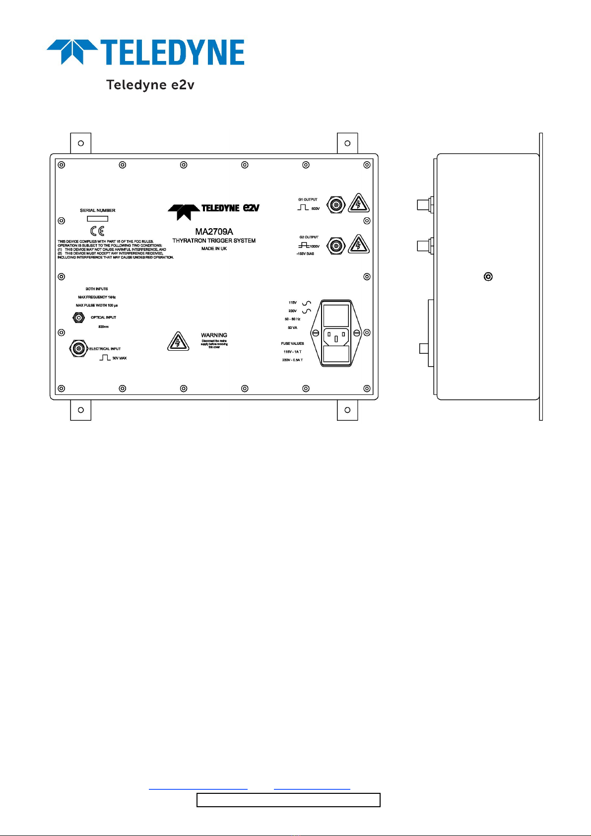
1. The MA2709A has a filtered changeover socket
to allow operation with either 115 ± 10% or 230
± 10% V ac mains input. The filter connects the
mains earth to the box via a 400 11H inductor
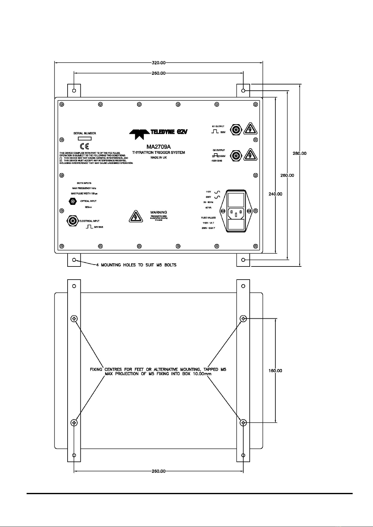
2. The unit can be fitted in any position. Two metal
strips are supplied with the unit; these can be
bolted to the back of the case to provide four
fixing feet with clearance holes for M5 bolts (see
Fig. 3). The operating manual supplied with the
unit has full details of methods of fitting.
3. The unit has not been tested to known levels of
shock and vibration, but is of generally rugged
construction. It should not be subjected to undue
shock and vibration.
4. The ambient temperature close to the unit must
be kept within the limits specified. No forced-air
or other external cooling is required, but when
operating near the maximum temperature, the
unit should be positioned so that heat can flow
away from the unit by convection or conduction.
5. The trigger level should be within the limits
quoted; if they are exceeded then possible
damage could occur to the unit
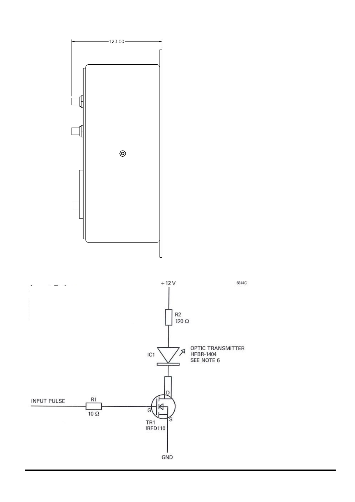
6. The optical input pulse is via the 9 mm FSMA
style connector - receiver type HFBR -2404.
Transmitter type HFBR -1404 is used for driving
and testing. To achieve the best performance,
the rise time of the input pulse should be as
short as possible; a suitable driver is shown in
Fig. 4.
7. Operating the trigger system at frequencies
higher than 1 KHz may cause internal damage
and overheating.
8. This is the open circuit voltage.
9. Outputs are via SHV BNC sockets. In order to
meet the EMC emission requirements, the SHV
BNC plugs must be wired with double-screened
cable.
10. The grid 1 resistor must be set so that the grid 1
current does not exceed the maximum specified
for the particular thyratron being triggered. If this
is not done, the thyratron may be triggered
detrimentally by the grid 1 pre-pulse instead of
the grid 2 pulse. Typical resistor values and
resulting grid 1 pulse currents are as follows:
G1 Resistor (Ω)
G1 Pulse Current
(A)
4.7
35+
6.8
28
10
26
15
23
22
18
33
14
50
10
* Exact value will depend on circuit inductance.
11. Measured at 50% pulse amplitude.
12. Measured between 10% and 90% amplitude
with no load connected.
13. The average current drawn from the negative
bias supply depends on the operating frequency
and the thyratron type. The negative bias
supply is generated from a capacitor driven
bridge circuit and therefore as the bias current
increases, the negative bias voltage falls linearly
at 2.5 V / mA
FAULT AND GRID SPIKE
PROTECTION
Protection features of the MA2709A:
•Transient Voltage Suppressors (TVSs) fitted
internally, together with more TVSs fitted
externally close to the thyratron (see above),
will protect the MA2709A from thyratron grid
spikes. With the external TVS protection
circuits fitted, the MA2709A has been shown
to withstand a 20 kV, 100 ns long, 20 ns rise
time spike at the grid 1 and grid 2 of a
thyratron
•Earthing of the MA2709A is via the coaxial
SHV BNC outer braids. The outer terminal of
the trigger input BNC socket is also
connected to the box and it may be necessary
to use a ferrite core to minimise earth currents
flowing along the input coaxial cable. See
Figs. 1 and 2 for practical earthing
considerations when fitting the MA2709A into
a circuit.
•The MA2709A will operate continuously into
an open circuit. The MA2709A will continue
to operate if the outputs are short-circuited,
but it is not designed to run continuously at
full power into a short circuit. The limiting
factor is the power rating of the internal grid 1
and grid 2 output resistors.
•The grid 2 negative bias falls to zero if the grid
2 output operates into a short circuit; no
internal fuse blows.
•There are three protective fuses: one in the
mains input socket to protect against failure of
the primary power supply components and
one in each of the supply rails to the grid 1
and grid 2 trigger circuits. The latter will blow
only if their FET switch fails short-circuit.
•If the input frequency exceeds 1 kHz the
output will stop. This prevents the MA2709A
being operated in excess of its designed
output power level.

© Teledyne UK Limited 2023 Document subject to disclaimer on page 1 A1A-MA2709A Version 12, page 4
HEALTH AND SAFETY HAZARDS
Teledyne e2v electronic devices are safe to handle
and operate provided that the relevant precautions
stated herein are observed. Teledyne e2v does not
accept responsibility for damage or injury resulting
from the use of electronic devices it produces.
Equipment manufacturers and users must ensure that
adequate precautions are taken. Appropriate warning
labels and notices must be provided on equipment
incorporating Teledyne e2v devices and in operating
manuals.
High Voltage
Equipment must be designed so that personnel
cannot come into contact with high voltage circuits.
All high voltage circuits and terminals must be
enclosed and fail-safe interlock switches must be
fitted to disconnect the primary power supply and
discharge all high voltage capacitors and other stored
charges before allowing access. Interlock switches
must not be bypassed to allow operation with access
doors open
STATUTORY AND REGULATORY
COMPLIANCE
Low Voltage Directive
This product complies with the requirements of the
Low Voltage Directive 2014/35/EU.
Electromagnetic Compatibility
This product complies with the requirements of the
Electromagnetic Compatibility Directive
2014/30/EU.
This device complies to Federal
Communications Commission (FCC) Rules &
Regulations for Title 47 (CFR 47), Part 15,
Class B.
Operation is subject to the following two
conditions:
(1) This device may not cause harmful
interference and
(2) This device must accept any
interference received, including interference
that may cause undesired operation.

© Teledyne UK Limited 2023 Document subject to disclaimer on page 1 A1A-MA2709A Version 12, page 5
CONNECTION SCHEMATIC
Fig.1 MA2709A remote from the thyratron discharge circuit
Fig.2 MA2709A mounted close to the thyratron discharge circuit

© Teledyne UK Limited 2023 Document subject to disclaimer on page 1 A1A-MA2709A Version 12, page 6
Fig.3 Box Layout and mounting (All dimensions nominal and in mm)

© Teledyne UK Limited 2023 Document subject to disclaimer on page 1 A1A-MA2709A Version 12, page 7
Fig.4 Suitable drive circuit for optic transmitter
Input Pulse
Amplitude 10 V
Pulse Width 1 µs
Rise Time 0.1 µs
Table of contents
Other Teledyne Industrial Equipment manuals